Table of Contents
Advertisement
Quick Links
BT-CT66 Multi-function Wire Tracker
User Manual
•
Thank you for purchasing the Wire Tracker. Please read the manual before using the Wire Tracker and use
properly.
•
For using the Wire Tracker safely, please first read the (Safety Information) carefully in the manual.
•
The manual should be kept well in case of reference.
•
Keep the S/N label for after-sale service within warranty period. Product without S/N label will be charged for
repair service.
•
If there is any question or problem while using the Wire Tracker, or damages occurred on the product, please
contact our technical Department.
Advertisement
Table of Contents

Summary of Contents for BEEK BT-CT66
- Page 1 BT-CT66 Multi-function Wire Tracker User Manual • Thank you for purchasing the Wire Tracker. Please read the manual before using the Wire Tracker and use properly. • For using the Wire Tracker safely, please first read the (Safety Information) carefully in the manual.
-
Page 2: Table Of Contents
BT-CT66 Multi-function Wire Tracker User Manual Content 1. Safety information ....................... 1 2. Feature ..........................3 3. Packing list ..........................3 4. Interface and Function Introduction ................... 4 5. The instruction of product application ................7 5.1 Cable tracer ........................ 7 5.2 UTP detection ...................... -
Page 3: Feature
BT-CT66 Multi-function Wire Tracker User Manual 2. Feature • Secondary code digital mode, decisively rejects noise and false signals, locate cables quickly and easily. • Cable tracer and UTP cable test in the same interface. • Identify cable type:100M/1000M, straight/cross/other. -
Page 4: Interface And Function Introduction
BT-CT66 Multi-function Wire Tracker User Manual 4. Interface and Function Introduction 1) Emitter Interfaces and functions: 1 Telephone status indicator 2 Functions switch: SCAN/UTP, OFF, UTP cable test 3 UTP cable sequence/ continuity indicators, G is shielded cable 4 UTP cable type indicator: straight /cross /other... - Page 5 BT-CT66 Multi-function Wire Tracker User Manual Top interface Left interface 11 BNC interface 12 UTP/ Scan port 13 RJ11 port Note: Please use telephone status detection in the OFF status. The indicator light off / on / flashing correspond to telephone status standby / ringing / off-hook.
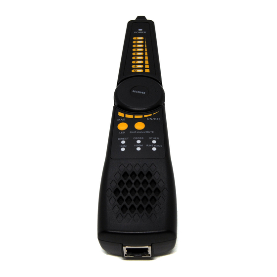
- Page 6 BT-CT66 Multi-function Wire Tracker User Manual 1 LED light 2 Power Indicator 3 UTP cable sequence / signal strength indicator Shielded layer continuity indicator Earphone jack UTP cable test port LED light switch 8 100M /1000M indicator 9 Switch / Sensitivity knob...
-
Page 7: The Instruction Of Product Application
BT-CT66 Multi-function Wire Tracker User Manual The instruction of product application Cable tracer Connect the network cable into the emitter’s RJ45 port, connect BNC cable or RJ11 telephone line to the emitter’s BNC or RJ11 port. If no connector cable, can use alligator clips to clip the bare copper wire. -
Page 8: Utp Detection
BT-CT66 Multi-function Wire Tracker User Manual (3) Quickly verify the tracking result (only for RJ45 port). After found the cable, connect the network cable to wire receiver “UTP” port for pair line detection. For example, When the “Straight/Cross/Other” lights up, indicates the verification of the matching cable. -
Page 9: Network Cable Port Continuity Detection
BT-CT66 Multi-function Wire Tracker User Manual 5.2.2 Network cable port continuity detection In the UTP mode, press “SET” key to switch “LOCAL” mode. Local port continuity detection: when the “LOCAL” indicator is on, connect the other end of network cable to wire receiver “UTP”... -
Page 10: Short Circuit Test
BT-CT66 Multi-function Wire Tracker User Manual Under UTP mode, press “SET” key to switch to the “REMOTE” function Remote end continuity detection: The “REMOTE” indicator is on, connect the other end of the cable to the UTP port of Receiver. -
Page 11: Continuity Detection In The State Of Connected Switches
BT-CT66 Multi-function Wire Tracker User Manual 5.2.4 Continuity detection in the state of connected switches Under UTP mode, press “SET” key to switch to the “SWITCH” function. When connected to a switch, 1-8, G indicator indicates the continuity of the cable, lights on means connected, lights off means disconnected (The 100M switch is 1236 line connected, the 1000M switch is 1-8 lines connected). -
Page 12: Other Features
BT-CT66 Multi-function Wire Tracker User Manual 5.4 Other features Line DC level and positive / negative polarity testing Turn off the emitter, the red and black wire clip of BNC cable connect to the telephone line or battery, the other end connect to BNC port. (Note: If the telephone cable with welled RJ45 connectors, directly connect...
Need help?
Do you have a question about the BT-CT66 and is the answer not in the manual?
Questions and answers