Table of Contents
Advertisement
Quick Links
About this Practice:
• This practice has been reformatted
to meet ISO 9001 requirements.
Reissued Practices: Updated and
new content can be identified by a
banner in the right margin.
Issue date: September 1997
Copyright 1997 by Dantel, Inc. • Dantel is a registered trademark of Dantel, Inc. • ISO 9001 Registered
H
UBBING
Table of Contents
CAUTION
•
Install or remove modules from the shelf only when the power is off.
If you install a module in the shelf with the power on, the internal
circuitry may suffer damage and the product warranty will be void.
•
Remove and install circuit boards only in a static-safe environment
(use antistatic wrist straps, smocks, footwear, etc.).
•
Keep circuit boards in their antistatic bags when they are not in use.
•
Do not ship or store circuit boards near strong electrostatic, electromag-
netic, magnetic, or radioactive fields.
•
For more complete information on electrostatic discharge safety
precautions, refer to Bellcore
Printed in the U.S.A.
I
NSTALLATION
46034
M
ODULE
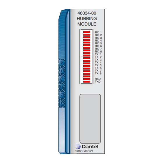
46034-00
HUBBING
MODULE
RX 1
RX 2
RX 3
RX 4
RX 5
RX 6
RX 7
RX 8
TX 1
TX 2
TX 3
TX 4
TX 5
TX 6
TX 7
TX 8
RXD
TXD
46034-00 REV__
Technical Reference # TR-NWT-000870.
TM
& O
M
PERATION
ANUAL
46034-0997 <90-00030>
Advertisement
Table of Contents

Summary of Contents for Dantel 46034
- Page 1 For more complete information on electrostatic discharge safety precautions, refer to Bellcore Technical Reference # TR-NWT-000870. Issue date: September 1997 Copyright 1997 by Dantel, Inc. • Dantel is a registered trademark of Dantel, Inc. • ISO 9001 Registered Printed in the U.S.A.
-
Page 2: Ordering Information
ORDERING INFORMATION NOTE: 1-800-432-6835. OPTION NUMBER FEATURES B11-46034-00 Hubbing Module GENERAL DESCRIPTION CIRCUIT DESCRIPTION 46034-0997 <90-00030>... - Page 3 CIRCUIT DESCRIPTION ♦ ♦ ♦ ♦ ♦ 46034-0997 <90-00030>...
- Page 4 CIRCUIT DESCRIPTION . 1 - 46034 H UBBING ODULE UNCTIONAL CHEMATIC +5 VDC PORT +5 VDC DATA STRAP 1A-8A DATA DATA RS-232 RS-422 DATA RS-232 RS-422 DATA RX1 + DATA Input Data Port RX1 - Data Port 1 S22 1-8...
- Page 5 CIRCUIT DESCRIPTION A - PC P RS-422 P ABLE SSIGNMENT FOR ORTS PORT NUMBER RS-422 TX+ RS-422 TX- RS-422 RX+ RS-422 RX- B - PC P RS-232 P ABLE SSIGNMENT FOR ORTS PORT NUMBER RS-232 TD RS-232 RD 46034-0997 <90-00030>...
-
Page 6: Application Information
Use each of the six buses carrying data between the data communication ports for one data polling system only. If more than one alarm polling system’s data routes to a bus, the system does not function properly. . 2 - 46034 H UBBING ODULE PPLICATION... - Page 7 APPLICATION INFORMATION UMMING AND ISTRIBUTION PPLICATIONS RIDGING PPLICATIONS 46034-0997 <90-00030>...
- Page 8 DIP Switch S11 RS-422 S22-6 All Switches=Off Output Strap 1B - 8B (NC) RS-232 Buses A-F To Other Data Ports Data Ports 4 through 8 are treated the same as 1, 2 and 3 shown above strapped for RS-422 46034-0997 <90-00030>...
- Page 9 DIP Switch S10-1=On S22-7 All Switches=Off Strap 1B - 8B RS-232 RS-422 Output Data Ports 1 and 2 are shown strapped for RS-422 as examples. all other Data Ports are treated similarly Buses A-F To Other Data Ports 46034-0997 <90-00030>...
- Page 10 CF leads are to be used. For bridging application, put BB and BA on same bus; CA and CF on same bus. For Buses A-F summing application, put output BB port on BA bus; put To Other output CA port on CF bus. Data Ports 46034-0997 <90-00030>...
-
Page 11: Installation
INSTALLATION 1. Install the subassembly. . 6 - S UBASSEMBLY AND OWER UPPLY OCATIONS Retaining Screws Power Supply Current Loop Tone Modem Retaining Screws . . . CONTINUED 46034-0997 <90-00030>... - Page 12 INSTALLATION 2. Set the straps and switches. . 7 - S WITCH AND TRAP OCATIONS 2 1 3 2 1 3 2 1 3 2 1 3 2 1 3 . . . CONTINUED 46034-0997 <90-00030>...
- Page 13 TRAP PTIONS OPTION STRAP POSITION DATA PORTS 1 THROUGH 8 COMMUNICATIONS SUBASSEMBLY D - S ABLE WITCH ETTINGS DATA PORT NUMBER SWITCH BUS A BUS B BUS C BUS D BUS E BUS F . . . CONTINUED 46034-0997 <90-00030>...
- Page 14 CONTINUED WITCH ETTINGS DATA PORT NUMBER SWITCH BUS A BUS B BUS C BUS D BUS E BUS F DUPLEX ON PORTS 1-8 PORT SWITCH PORT SWITCH 3. Wire the connector. 4. Install the module in the shelf. 46034-0997 <90-00030>...
- Page 15 Port 1: RS-422 RX-; RS-232 RD Port 1: RS-422 RX+ Port 1: RS-422 TX+; RS-232 TD Port 1: RS-422 TX- COMPONENT SIDE CIRCUIT SIDE OF PC BOARD OF PC BOARD INTERFACE PIN 56 PIN 55 PIN 54 PIN 53 PIN 36 PIN 18 46034-0997 <90-00030>...
-
Page 16: Operation
OPERATION . 9 - 46034 F RONT ANEL 46034-00 HUBBING MODULE RX 1 RX 2 RX 3 RX 4 RX 5 RX 6 RX 7 RX 8 TX 1 TX 2 TX 3 TX 4 TX 5 TX 6 TX 7... -
Page 17: Technical Specifications
TECHNICAL SPECIFICATIONS DESCRIPTION VALUE 46034-0997 <90-00030>... -
Page 18: Warranty
4. Connections between Dantel’s equipment and your equipment. 1-800-4DANTEL (1-800-432-6835). 1-800-4DANTEL Dantel, Inc. • 2991 North Argyle Avenue • Fresno, California 93727-1388 P.O. Box 55013 • Fresno, CA 93747-5013 Phone (209) 292-1111 Fax (209) 292-9355 http://www.dantel.com 46034-0997 <90-00030> 18 P AGES...
Need help?
Do you have a question about the 46034 and is the answer not in the manual?
Questions and answers