
Related Manuals for ES SYSTEM K 60

Summary of Contents for ES SYSTEM K 60
- Page 1 ORIGINAL USER MANUAL Multicooler ES SYSTEM K SP. Z O.O. ul. Wrzosowa 10 32-340 Wolbrom, Małopolska Province www.essystemk.com e-mail info@essystemk.pl e-mail serwis@essystem.pl...
- Page 2 LEGEND Manual transport. Prior to use, read this instruction manual. Transport lugs. Warnings and notes. Adjustable components may raised indicated points This device is equipped with rotational only. elements and sharp edges. Wear protective gloves Do not place any items on the and disconnect the device from the mains covers.
- Page 3 1. General information 1.1. Warranty 2. Device 2.1. Type of device 2.2. Limitations 2.3. Packaging and transport conditions 2.3.1. Lifting and transport lugs of the device 2.4. Transport damages 3. Placement of the device 3.1. Placement of the devices in a sequence 3.2.
-
Page 4: General Information
relative humidity 60% RH; ambient temperature +25°C; ambient air flow rate < 0.2 m/s. ATTENTION: Accidental or any other acts of windowpane or lighting item breaking shall not be covered by the warranty. - Page 5 2. Device The dynamic refrigerator Multicooler is a device used for exposition, storage and direct sale of products at a temperature of 0 to +4 C. The device has insulated panels on three sides, and on its front side there is a hinged self-closing door with double glazed glass. Consequently, the device allows for exact presentation of products stored inside it and its exposure to heat losses is lower.
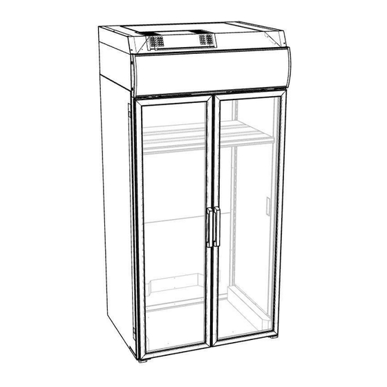
- Page 6 Description of the diagram: 1. Internal bumper 7. Banner 2. Insulation case 8. Lighting panel 3. Structural column 9. Door handle 4. Exposition shelf 10. Door (optional) 5. Monoblock 6. Fluorescent lamp of the banner...
- Page 7 230 [V] 50 [Hz] cooling Type of device Temperature class 0 ÷ +4 Temperature range * R290 Cooling agent Thickness of sides [dB] <70 Noise emitted by the device *) for ambient conditions: temperature +25 [ C], relative humidity 60 [%].
- Page 8 2.1. Type of device The Multicooler refrigerator occurs only in the refrigerating version and is provided with a specially prepared cooling monoblock consisting of: refrigerating unit, evaporator, air supply ventilators. This device is not intended for connection to external units. The device is not intended for connection into sequences by twisting - only by adding further modules.
- Page 9 2.3. Packaging transport conditions Transport of the unit to its final location, as far as possible, is recommended to be carried out using the manufacturer's original packaging. ATTENTION: Do not stack the cases one on top of the other Materials used for packagings are subject to recycling. 2.3.1.
-
Page 10: Transport Damage
2.4. Transport damage The unit shall be unpacked and checked for damage that might have occurred in the course of transport. In case of such damage, the seller (sales representative, final vendor) or the manufacturer of the unit shall be informed immediately. 3. -
Page 11: Electrical System
ATTENTION: All sequencing actions may be carried out only by suitably qualified personnel. Attention: The manufacturer shall not be responsible for damages occurring from inappropriate connection of the unit to the installation. 3.1. Placing the devices in a sequence In the case of a multicooler, it is possible to sequence the devices. The devices are placed by pulling successive units to one another in any configuration of modules. - Page 12 The device is adapted for 230 V, 50 Hz alternating power supply through a wire equipped with a plug. ATTENTION: If the device is equipped with power cable with a plug, then it is necessary to insert it only to a socket with a protective pin! Electrical socket must be equipped with protective pin (earthing) and secured with suitable 15 [A] time delay cut-out.
- Page 13 Connecting electrical system shall be provided as per diagrams stated below. Electrical diagrams Controller Electrical strip Side lighting...
- Page 14 Upper lighting Banner Monoblock...
-
Page 15: Refrigerating System
3.2.3. Sanitary system The device is not equipped with a condensate removal system. Condensate is evaporated by means of hot gas. 3.3. Assembly of the monoblock Multicooler 60 Place and screw down the cooling monoblock. - Page 16 1. Screw down the top side extensions to brackets (using middle holes - extreme holes shall be used in pt 4 during the assembly of the rear masking cover). 2. Screw down the top masking cover to the top side extensions. 3.
- Page 17 Multicooler 107 Enter the monoblock onto the device by means of guide bars. Protect the monoblock against shifting by means of locking devices.
- Page 18 Protect the monoblock against shifting by means of locking devices. 1. Screw down the roof of the monoblock to the top side extensions. 2. Screw down the cover of the condenser to the masking cover 3. Attach the rear masking cover of the top side extension to the brackets of the top side extension.
- Page 19 Multicooler 162 Enter the monoblocks onto the device by means of guide bars. Protect the monoblock against shifting by means of locking devices.
- Page 20 Protect the monoblock against shifting by means of locking devices. Perform the following steps for each monoblock: 1. Screw down the roof of the monoblock to the top side extensions. 2. Screw down the cover of the condenser to the roof. 3.
-
Page 21: Operation
3.4. Replacement of the controller Remove the suspended banner. Detach the power supply unit. Disassembly the plexi panel of the banner. Remove and replace the controller. Connect according to the diagram. Operation All information and notes related to the first start-up and correct operation of the unit have been specified in this section. -
Page 22: Product Display
4.2. Start-up ATTENTION: Before the start-up of the device after its transport and positioning in the intended place, wait 60 minutes. Devices equipped with internal refrigerating unit Check if the power cable is not damaged. Turn on the main switch of the electrical system. - Page 23 Additionally, in case of cabinets equipped with refrigerating unit: Do not cover ventilating holes located on the metal sheets that protect the frame. Do notcover ventilation holes in metal sheets that protect the refrigerating unit. NOTE: The refrigerated cabinet is not designed for freezing the products but only for storing them.
-
Page 24: Displayed Messages
Timer: this symbol is visible when timer is active or when one of time limits is active. Upon switching on, this symbol appears for a couple of seconds as an information related to timer availability. Alarm: this symbol is visible when alarm is active UP/ON OFF during normal operation of controller: pressing it and holding down for more than 3 sec. - Page 25 4.5.2. Temperature settings control Temperature was previously set by the manufacturer to optimal value on the basis of operational range which is designed for a particular unit. The user may alter operational temperatures only within operational temperature range. Temperature ranges are specified in a table in section 2. The temperature change procedure can be activated as follows: Pushand hold SET button until the temperature value flashes.
- Page 26 “STAND-BY” (ESC) button Escape Alarm Return to previous menu level. Is lit when the alarm is active. Flashes Confirmation of parameter value. when the alarm is muted. Activation of stand-by mode (par. H08). “SET” button Alarm display (when activated) Is lit when the fan is running. Entering basic menu.
-
Page 27: Automatic Defrosting
Press and hold „UP” button for 5 seconds. If temperature in the cooler exceeds setup temperature for de-frosting completion, the display will flash 3 times and de-frosting shall not commence. NOTE: In case of application of a controller that has not been listed above, additional manual will be enclosed by the manufacturer. -
Page 28: Cleaning Of The Condenser
4.8.1 Cleaning condenser (applies to devices with the integrated refrigerating unit) The reason for frequent failures or malfunctions ofrefrigerating units may becontamination of the condenser. Cleanness of condenser is recommended to be checked at least once a month. It is a user's obligation. If necessary, remove the dust from the condenser ribs and check for impurities blocking the air flow and check for any obstacles between the ribs that hinder the air flow. -
Page 29: Service And Spare Parts
NOTE: Insignificant differences of temperature readings may occur at various locations of the display area in the device. NOTE: In case of refrigerating units, it is necessary to check regularly if the condenser is clean and if air flow through inlet and outlet holes is not clogged by product residues, used packages and similar material. - Page 30 5. Rotate the fluorescent lamp around its axis to fit it correctly in the fixture; 6. Turn on the unit. ATTENTION: use only fluorescent lamps which conform to the manufacturer's recommendations. NOTE: In case of equipment, in which fluorescent lamps with double shelter were used, these may be replaced for identical items only.
Need help?
Do you have a question about the 60 and is the answer not in the manual?
Questions and answers