
Summary of Contents for LCM SYSTEMS TR150
- Page 1 SYSTEMS Solutions in Load Cell Technology Solutions in Load Cell Technology TR150 Portable Battery Powered Indicator Instruction Manual Software version V2.XX...
-
Page 2: Table Of Contents
Sensor connections RS232 port connections Internal connections Menu structure Configuration menu Calibration menu Operation features Normal display operation Switching the TR150 on and off RANGE button HOLD button GROSS/NET button SHUNT CAL button PEAK button TROUGH button Configuration menu parameters... -
Page 3: What Is Teds
Providing tangible benefits through engineering expertise and integrity What is TEDS? " Plug and play sensor hardware and software make configuring a smart TEDS sensor as easy as plugging a mouse into a PC. The technology has greatly improved efficiency and productivity by completely eliminating manual sensor configuration."... -
Page 4: Advantages
Advantages Plug and play sensors are revolutionising measurement and automation. With Transducer Electronic Data Sheets (TEDS), your data acquisition system can detect and automatically configure sensors. This technology provides: Reduced configuration time by eliminating manual data entry Ÿ Better sensor tracking by storing data sheets electronically Ÿ... -
Page 5: Introduction
Important Note The TR150 is supplied calibrated to a particular load cell. All user functions are available via the front keypad. Do NOT attempt to re-calibrate the TR150, unless you are authorised and have the equipment available to do so. -
Page 6: Electrical Connection Information
PIN 5 TEDS RS232 Port Connections If the TR150 has been ordered with the optional RS232 output, then this will be available via a 8 pin 723 series Binder connector. The wiring for this is as detailed below:- PIN 1... - Page 7 Providing tangible benefits through engineering expertise and integrity There are six push buttons on the front panel of the TR150, which are available for use in normal operation. Each of these is described below: Front Panel Button Function of Button in Normal Operation Mode...
-
Page 8: Menu Structure
Menu Struture The TR150 has two menus, details of which are outlined below:- A CONFIGURATION MENU, which enables the user to tailor the operation to meet a specific application requirement. The values selected in the CONFIGURATION MENU are completely independent for each range. - Page 9 Providing tangible benefits through engineering expertise and integrity...
-
Page 10: Configuration Menu
This allows the setting of a visual overload. The value entered is the display value at which SEt OUEr the TR150 displays OVErLOAd. Values between -9999999 and +9999999 can be entered, using the arrows to select a digit and the arrows to increment or decrement the digits. - Page 11 RS232 format are provided further into this manual. The RS232 output is rS232 an option that has to be ordered with the TR150. To conserve battery life, it is suggested that the RS232 output is disabled, when it is not required.
-
Page 12: Calibration Menu
To select 50mV/V you need to power down the unit and access the internal circuit board. Move link LK1 and place it onto JP1. Power on the TR150 and return to this point of the calibration menu. You will notice that the menu parameter has changed to SEnS 50.0, press to change the sensitivity to 50mV/V and move on to the next parameter. - Page 13 Providing tangible benefits through engineering expertise and integrity ENABLING TEDS DISABLES CALIBRATE MENU Press to skip this parameter and exit menu Press to enable or disable TEDS. tedS If you have chosen to enter the TEDS calibration, EnAbLEd? appears. If you have chosen to enter the TEDS you will be prompted whether you want to select EnAbLEd? if you do not press , otherwise press .
-
Page 14: Operation Features
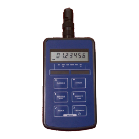
Normal Display Operation The TR150 has a full 7 digit display, which can be scaled using the calibration menu to suit the application it is to be used in. The display can display the instantaneous, peak or trough values. It is also possible to hold the display value (this only operates when not in peak or trough mode). -
Page 15: Hold Button
PEAK Button When pressed this button puts the TR150 into peak mode. This will display the highest display reading and hold it on the display until it is reset or a higher value is reached. To reset the peak display, press the peak and trough buttons simultaneously. -
Page 16: Configuration Menu Parameters
The TR150 has a special power saving mode, which can be enabled or disabled within this parameter, pressing when asked whether you wish to select P SAvE? will put the TR150 into power save mode for the RANGE selected. Pressing will de-activate the power save facility. - Page 17 The AUtO OFF parameter is another power saving feature. It allows for the setting of a time period in minutes, between 05 and 99 (00 de-activates AUtO OFF). i.e. if this was set to 25, then if the TR150 detects no keyboard activity for a continuous 25 minute period, then the TR150 will power down, to conserve power.
-
Page 18: Calibration Menu Parameters
If however, a higher sensitivity sensor is used with the TR150, it will be necessary to gain access to the internal PCB (you must turn the TR150 off) to move link LK1 to JP1 (see picture below) to allow the TR150 to accept sensitivities of up to 50mV/V. -
Page 19: Calibration Procedures
TR150 automatically. If this is not possible, then the sensitivity figure (in mV/V) from the sensor calibration certificate can be used to scale the TR150, by using the tAbLE calibration. This may be the only option available if you are unable to apply a known stimulus to the sensor, which quite often is the case. -
Page 20: Specifications
Low Voltage Directive 2006/96/EC EMC Directive 2004/108/EC Control Variables Front panel user keys ON/OFF Switches TR150 power on/off RANGE Selects between two ranges HOLD Hold the current display value, press again to release GROSS/NET Zero’s display (±100% range) SHUNT CAL...