Table of Contents
Advertisement
Quick Links
Advertisement
Table of Contents

Summary of Contents for Mid-tech Legacy 6000
- Page 1 Legacy 6000 User Guide Fieldware Fieldware For Legacy 6000 98-05053...
- Page 3 USER GUIDE PN - 98-05053...
-
Page 5: Table Of Contents
Chapter 1 - System Introduction ..................1-1 System Introduction ...................... 1-2 Mid-Tech CAN Bus System Overview................. 1-5 The Legacy 6000 Console ..................1-5 CAN Modules (PCM, SSM, PSM) ................1-10 Typical Legacy 6000 Configurations................1-13 Single Channel Liquid Flow Meter ................. 1-13 Chapter Notes....................... - Page 6 Chapter 4 - Real-time Operation..................4-1 Product Application....................... 4-2 System, Warning and Error Messages ..............4-10 Real-time Guidance Operation................... 4-14 Lightbar Curved Guidance Graphics ................ 4-26 Applied Area Detection ....................4-27 Detecting A Previously Applied Area ..............4-27 Detecting Neighboring Swath.................. 4-27 Mapping a Field Boundary ..................
-
Page 7: Chapter 1 - System Introduction
Chapter 1 - System Introduction An introduction to the Legacy 6000 System. Fieldware for the Legacy 6000 Version 1 Midwest Technologies IL, LLC Fieldware for the Legacy 6000... -
Page 8: System Introduction
Software Version 1 System Introduction The Legacy 6000 system allows the control of all product types, plus GPS mapping, guidance, and data collection in a single console. Replacing multiple consoles in the cab with one robust system, Mid-Tech's Legacy 6000 sets a new standard for control systems of the future. - Page 9 The Legacy 6000 uses 4 types of modules, each having a unique function. Each described in more detail below. The console in the cab is one of these modules and serves as the user inter- face.
- Page 10 Legacy 6000 system, and enjoy straight-line, curved or center pivot guidance at your command. Application maps can be viewed on the Legacy 6000 display as you apply. Cross track error, area applied, application rates, and other vital information display on the Swath XL lightbar in real time.
-
Page 11: Mid-Tech Can Bus System Overview
Software Version 1 Mid-Tech CAN Bus System Overview The Mid-Tech CAN bus system is comprised of several components (modules). The Console, the Power Speed Module (PSM), the Switch Sense Module (SSM), a Product Control Module (PCM), and a Lightbar. At a minimum, four of these modules are required to have a fully functional Legacy 6000 single product control system. - Page 12 Speed 2: digital, 0-12 VDC, optimized for 50% duty cycle, 0-5 KHz, secondary input Ignition sense: digital, 0-12 VDC, (Hi state is ON) Inputs/Outputs Mid-Tech CAN: Bosch 2.0B, 29 bit ID, 250K baud Gateway CAN: Bosch 2.0B, 11 or 29 bit ID, 250K baud Serial RS 232: Txd, Rxd, Rts, Cts and ground.
- Page 13 Booms inputs: up to 20, digital, 0-12 VDC, HI/LO sensing Ground speed override:1 input, digital, 0-12 VDC, HI/LO sensing Machine status: 1 input, digital, 0-12 VDC, HI/LO sensing Input/Outputs Mid-Tech CAN: Bosch 2.0B, 29 bit ID, 250K baud Chapter 1 - System Introduction Mid-Tech CAN Bus System Overview...
- Page 14 Software Version 1 Product Control Module The Product Control Module (PCM) performs the actual control function for the Mid-Tech CAN Bus and connects the actuator and sensor. Control outputs can be bi-directional. One PCM is required for each product you wish to control.
- Page 15 Software Version 1 Swath XL Lightbar A CAN based Swath XL Lightbar was developed specifically for the Legacy 6000 system. The Lightbar is required for applications using guidance and recommended for non-guidance uses as well. In non-guidance use (logging data only) the lightbar can provide area and rate feed back.
-
Page 16: Can Modules (Pcm, Ssm, Psm)
Fieldware for The Legacy 6000 Software Version 1 CAN Bus Cable Specifications 5-wire cable with molded connectors. Male or female terminator required on each end. Pin 1: Ground Pin 2: +12V Pin 3: Reserved Pin 4: CAN High Pin 5: CAN Low... - Page 17 Fieldware for The Legacy 6000 Software Version 1 Cable Harnesses Power Speed Module (PSM) Figure 1-6: Power Speed Module Harness Switch Sense Module Figure 1-7: Switch Sense Module Harness Options Chapter 1 - System Introduction 1-11 Mid-Tech CAN Bus System Overview...
- Page 18 Fieldware for The Legacy 6000 Software Version 1 Product Control Module Figure 1-8: Power Control Module Harness PCM Cable Options Sensor Inputs Part Number Valve Sen. Description 45-06300 Single Sensor 45-06301 Single Sensor w/rpm 45-06302 Dual Sensor w/rpm 45-06303 Single Sensor w/press...
-
Page 19: Typical Legacy 6000 Configurations
Software Version 1 Typical Legacy 6000 Configurations The following schematics reflect some typical Legacy 6000 configurations. Due to the variety of possible configurations, these schematics should be used for general reference. Contact Midwest Technologies or your dealer for detailed information regarding your specific configuration and installation. - Page 20 Fieldware for The Legacy 6000 Software Version 1 Single Channel Granular Spreader This is a typical single product granular configuration with spreader control. Figure 1-10: Single Channel Granular Spreader Configuration 1-14 Chapter 1 - System Introduction Typical Legacy 6000 Configurations...
- Page 21 Fieldware for The Legacy 6000 Software Version 1 Dual Channel Granular with Spreader Control This configuration is typical of a two product granular application with spreader control. Figure 1-11: Dual Channel Granular Spreader Configuration Chapter 1 - System Introduction 1-15...
- Page 22 Fieldware for The Legacy 6000 Software Version 1 Dual Channel with Wet and Dry Booms This is a typical two product configuration, one liquid and one dry, for a vehicle with wet and dry booms. Figure 1-12: Dual Channel Granular Spinner Configuration...
- Page 23 Fieldware for The Legacy 6000 Software Version 1 Chapter 1 - System Introduction 1-17 Typical Legacy 6000 Configurations...
- Page 24 Fieldware for The Legacy 6000 Software Version 1 Dual Channel Granular with Two Sensors per Channel This is a typical two product granular layout with two slotted rate sensors per channel. Figure 1-13: Dual Channel Granular with Two Sensors per Channel...
-
Page 25: Chapter Notes
Fieldware for The Legacy 6000 Software Version 1 Chapter Notes Chapter 1 - System Introduction 1-19 Chapter Notes... - Page 26 Fieldware for The Legacy 6000 Software Version 1 1-20 Chapter 1 - System Introduction Chapter Notes...
-
Page 27: Chapter 2 - Getting Started
Chapter 2 - Getting Started Setting up "Fieldware for the Legacy 6000". Software Version 1 Midwest Technologies IL, LLC Fieldware for the Legacy 6000... -
Page 28: Software Overview
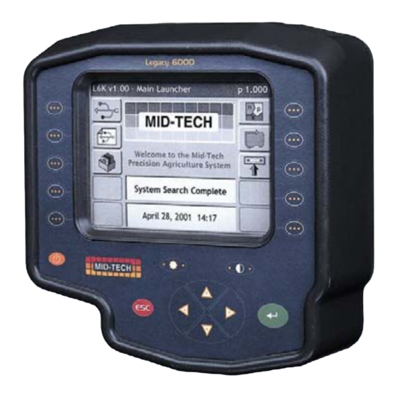
Figure 2-1: The Legacy 6000 Console Powering Up To power up the Legacy 6000 console, press the orange button to the left side of the console face- plate (Figure 2-1). When the Legacy 6000 console has been powered up, "Fieldware for the Leg- acy 6000"... -
Page 29: Standard Pages
Figure 2-2: Main Launcher Page Standard Pages Three basic types of software pages are used in "Fieldware for the Legacy 6000", a Launcher page (Figure 2-3), a Setup Menu page (Figure 2-4), and a Data Entry page (Figure 2-5). Each is described in more detail below. - Page 30 Fieldware for the Legacy 6000 Software Version 1 Software Version, page name and number Help Window Highlighted Button Figure 2-3: Example of a Launcher Page Chapter 2 - Getting Started Software Overview...
- Page 31 Fieldware for the Legacy 6000 Software Version 1 Setup Menu Page A Setup Menu page (Figure 2-4) is a page that contains all of the setup parameters associated with a particular setup theme, such as GPS Receiver. A Setup Menu page can be divided into three columns, Left, Center and Right.
- Page 32 Fieldware for the Legacy 6000 Software Version 1 Left Column Center Column Right Column Back Arrow Forward Arrow Exit & No Save Save & Exit Highlighted Setup Parameter Sub-group buttons Scroll bar Figure 2-4: Example of a Setup Menu Page...
- Page 33 Software Version 1 Data Entry Page The Data Entry page is used throughout the Legacy 6000 software suite. Depending on the setup parameter being edited, a Data Entry page may be an alpha-numeric entry or a pick list (Figure 2- 5).
- Page 34 Fieldware for the Legacy 6000 Software Version 1 Forward Arrow Back Arrow Save & Exit Exit & No Save Name of Setup Parameter Setting description and help text window. Figure 2-5: Example of Pick List Data Entry Page Left most character space in the data entry dialog box.
-
Page 35: System Setup
Software Version 1 System Setup The Fieldware System Setup allows the configuring of the Legacy 6000 to best suit job needs. To access the System Setup launcher press the top left button in the Main Launcher page (Figure 2- 2), the help text should say Configure System Settings . This brings up the System Setup Launcher page (Figure 2-7). -
Page 36: Console Setup
Fieldware for the Legacy 6000 Software Version 1 Console Setup Console Setup defines system environment settings (units, language, time) that are displayed on the console and used in the rate control and guidance applications. To access Console Setup, select System Setup from the Main Launcher page (Figure 2-2), this brings up the System Setup page (Figure 2-7). - Page 37 Fieldware for the Legacy 6000 Software Version 1 Setting Description PC Card Indicates to the Legacy 6000 system that a PCMCIA data card is being used. Units Defines the system units: Metric or US. Language Defines the system language. System Date Sets the system date.
-
Page 38: Lightbar Setup
Fieldware for the Legacy 6000 Software Version 1 Lightbar Setup Lightbar setup defines how the Legacy 6000 console configures the lightbar. Lightbar setup parameters are listed in Table 2-3. To access Lightbar Setup, select System Setup from the Main Launcher page (Figure 2-2). This brings up the System Setup page (Figure 2-7). - Page 39 Fieldware for the Legacy 6000 Software Version 1 Setting Description Look Ahead The number of seconds ahead of the vehicle that the cross track error is calculated at (Typically 2.0 seconds). Alarm Defines the situation in which the alarm sounds. Settings are Off, Alarm, Hazards, and All.
-
Page 40: Gps Receiver Setup
Figure 2-10: The GPS Receiver Setup Menu Page Setting Description Use GPS Defines whether the Legacy 6000 system is using GPS. If using GPS this setting must be set to Yes. Accuracy Defines the accuracy of the DGPS receiver. Choices are RTK and Sub-meter. - Page 41 Fieldware for the Legacy 6000 Software Version 1 Setting Description Stop Bits Defines the selected com port stop bit setting. Parity Defines the selected com port parity. Table 2-4: The GPS Receiver Setup Settings Chapter 2 - Getting Started 2-15...
-
Page 42: Product Control Module Setup
The Product Control Module (PCM) setup is used to configure a PCM that is connected to the Mid- Tech 6000 CAN Bus. A PCM can not be configured if it is not connected to the Mid-Tech CAN Bus. Setting up a PCM is typically required in the following scenarios: the initial Legacy 6000 hardware installation, when an additional PCM is added to the system, or to modify an existing, already con- figured, PCM. - Page 43 Fieldware for the Legacy 6000 Software Version 1 Page Description Name Allows a setup configuration to be selected or saved. Defines the type of product application or device being controlled, such as Liquid or Granular. Select the drive circuit used to control the product delivery or device.
- Page 44 The first setup page is the PCM Favorite (Figure 2-12). From this page, select a predefined stan- dard PCM configuration. Some of these favorites are supplied by Mid-Tech and some may be cre- ated by the user. The default configuration is always the current configuration and is listed as <Loaded>...
- Page 45 Fieldware for the Legacy 6000 Software Version 1 Setting the Application Type The Application Setup page (Figure 2-13) allows the selection of the required type of product appli- cation. All other setup pages will be based on the type of application chosen on this page. There are five possible applications: Liquid, Granular, Seeder, NH3, and Motor.
- Page 46 Fieldware for the Legacy 6000 Software Version 1 Setting the Drive Type The next PCM Setup parameter is Drive Type. This is the type of drive circuit used to control the delivery of a product. The list of available drive types depends on the Application selected in the previous setup page.
- Page 47 Fieldware for the Legacy 6000 Software Version 1 Setting the Units When the Drive Type is selected, the next PCM Setup page is the Units page (Figure 2-16). The available units are based on the Application and Drive Type selected. There is an additional page associated with the Units page.
- Page 48 Fieldware for the Legacy 6000 Software Version 1 Selecting the Primary Sensor The Primary Sensor is the type of sensor used for the primary control function. The Primary Sen- sor types available in this pick list are based on the Application type selected. Each Primary sen- sor type has an associated Settings button (Figure 2-18) which goes to the Sensor Settings page (Figure 2-19).
- Page 49 Fieldware for the Legacy 6000 Software Version 1 Sensor Setting Definitions As mentioned, each sensor has an associated settings page. The settings in this page vary based on the type of sensor selected. Table 2-6 is a list of sensor setting definitions. The sensor selected may not have all of these settings on its associated settings page.
- Page 50 Fieldware for the Legacy 6000 Software Version 1 Selecting the Secondary Sensor The Secondary sensor is used in conjunction with a Primary sensor. The Secondary Sensor types, available in this pick list, are based on the Application type and Primary Sensor type selected (Fig- ure 2-20).
- Page 51 Fieldware for the Legacy 6000 Software Version 1 Selecting a Monitor A Monitor is a sensor that is not a Primary or Secondary sensor and is used to monitor the status of some element of the application delivery system, such as RPMs on a shaft sensor. Up to four monitor sensors can be used in the delivery system.
- Page 52 Fieldware for the Legacy 6000 Software Version 1 Figure 2-23: The Monitor Sensor Settings Page 2-26 Chapter 2 - Getting Started Product Control Module Setup...
- Page 53 Fieldware for the Legacy 6000 Software Version 1 Finishing the PCM Setup The final page in the PCM setup process is the Finish page (Figure 2-24). From the Finish page, save the PCM setup to a file for use later, or send the new settings directly to the PCM. Also review the current settings prior to saving or flashing the new settings (Figure 2-25).
- Page 54 Fieldware for the Legacy 6000 Software Version 1 Saving the PCM Setup to a File Pressing the Save to a File button in the Finish page takes you to a Save As page (Figure 2-26). Press the Save As button to save the current PCM configuration to a file. The Save As page allows the naming of the PCM Setup file, such as My Sprayer.
-
Page 55: Implement Setup
The X and Y Axes In "Fieldware for the Legacy 6000", a vehicle has two axes: an X and a Y. The X axis runs perpen- dicular to the center line of the vehicle and the Y axis is the center line of the vehicle (Figure 2-28). - Page 56 Swaths and Sections In version 1 of "Fieldware for the Legacy 6000" a vehicle can have as many as four swaths and and up to 20 sections total across all swaths. A vehicle with a single swath divided into three sec- tions is shown in Figure 2-28.
- Page 57 Fieldware for the Legacy 6000 Software Version 1 Entering the Implement Width The first page in the Implement Setup process is the implement width (Figure 2-29). This width is used for guidance purposes and is considered the distance between guidelines. This width is typi- cally determined by the vehicle swath or spread width.
- Page 58 Fieldware for the Legacy 6000 Software Version 1 Figure 2-30: Review of Implement Configuration 2-32 Chapter 2 - Getting Started Implement Setup...
- Page 59 The next page is Number of Swaths. Currently the maximum number of swaths that "Fieldware for the Legacy 6000" can handle is four. Select the desired number of swaths and press the forward arrow to move to the next Implement Setup page.
- Page 60 Fieldware for the Legacy 6000 Software Version 1 Entering the Number of Sections in a Swath The Sections page is where the number of sections are in a swath is entered. The maximum num- ber of sections is 20 (not 20 sections per swath, 20 sections for the entire system). When the cor- rect number of sections is entered in Swath 1, press the forward arrow button to move to the next setup page.
- Page 61 Fieldware for the Legacy 6000 Software Version 1 Setting the Section to Switch Assignment The Section to Switch page allows you to assign a physical boom switch to the current Swath Sec- tion. This allows the control of individual sections. This boom section activity is properly displayed in the real-time map view as well as properly recorded in the application file (.RCD).
- Page 62 Fieldware for the Legacy 6000 Software Version 1 Entering the Section Width The Section Width page is where the width of a section is entered. When the correct section width is entered, press the forward arrow button to move to the next setup page.
- Page 63 Fieldware for the Legacy 6000 Software Version 1 Entering the Offset Direction Y The Y direction offset is the direction, (along the center line of the vehicle) from the GPS antenna to the center of a swath (Figure 2-35). Refer to “The Vehicle Coordinate System” on page 2-29 for a description of the offset directions and distances.
- Page 64 Fieldware for the Legacy 6000 Software Version 1 The Offset Distance Y When the Y Offset Direction has been entered, enter the Y Offset Distance. This is the distance from the GPS antenna along the vehicle center line to the swath. Refer to “The Vehicle Coordinate System”...
- Page 65 Fieldware for the Legacy 6000 Software Version 1 Entering the Offset Direction X The Offset Direction X (Figure 2-37) is the direction perpendicular (left or right) of the vehicle cen- ter line that the center of a swath is offset. Typically this will be set to Centered, as most swaths are centered on the vehicle’s center line.
- Page 66 Fieldware for the Legacy 6000 Software Version 1 Setting the PCM Assignment The PCM Assignment page allows the assigning of a Product Control Module (PCM) to a swath or swaths. The PCM must be setup prior to assigning it to a swath. A swath can have a single PCM assigned to it or all PCMs assigned to it.
- Page 67 Fieldware for the Legacy 6000 Software Version 1 Completing Implement Setup When all swaths and sections have been properly setup, the last Implement Setup page is the Fin- ish page. There are two buttons on the Finish page: a Review Configuration button and a Save to SSM button.
-
Page 68: System Tools
Fieldware for the Legacy 6000 Software Version 1 System Tools System Tools perform some basic system diagnostics. System Tools is accessed from the Main Launcher page (Figure 2-41). To access the System Tools launcher, press the Tools button in the Main Launcher page. - Page 69 Software Version 1 Tool Description CAN Bus This selection allows the viewing of all components on the Mid-Tech CAN Bus. Because this is Fieldware-SA, the only components available on the CAN Bus are the Console and Lightbar. GPS Receiver This selection allows the viewing of incoming GPS data which helps to deter- mine if the GPS Receiver is setup properly.
- Page 70 Software Version 1 The CAN Bus Tool This tool allows the viewing of any components connected to the Mid-Tech CAN Bus. See Table 2- 8 for a complete list of CAN components. To access the CAN Bus Diagnostic page, select System Tools from the Main Launcher page (Fig- ure 2-41), this brings up the System Tools page (Figure 2-42).
- Page 71 The need may arise to update the software in a CAN module such as a PCM. A typical reason for updating a module’s software is to install the latest release of the Mid-Tech CAN Bus software. A typical module update preserves all of your set-up data. Certain update situations may require that some system setups be run, when the update process is complete and power to the CAN Bus has been cycled.
- Page 72 Fieldware for the Legacy 6000 Software Version 1 To Module Flash Page Figure 2-44: The PCM Diagnostics Page Press to update module. Figure 2-45: Typical Module Flash Page 2-46 Chapter 2 - Getting Started System Tools...
- Page 73 Software Version 1 GPS Tool This tool allows the viewing of any GPS data coming into the com port on the Legacy 6000. This tool is useful when first connecting your GPS receiver to the Legacy 6000 console. It is recom- mended that this diagnostic be run the first time that the GPS receiver is connected to the Legacy 6000 console.
-
Page 74: Chapter Notes
Fieldware for the Legacy 6000 Software Version 1 Chapter Notes 2-48 Chapter 2 - Getting Started Chapter Notes... -
Page 75: Chapter 3 - Real-Time Setup
Chapter 3 - Real-time Setup Setting up Fieldware ARM for the Legacy 6000. Software Version 1 Midwest Technologies IL, LLC Legacy 6000... -
Page 76: Operation Overview
Fieldware for the Legacy 6000 Software Version 1 Operation Overview When the System Setup process is complete (See “Chapter 2 - Getting Started” on page 2-1.), product application setup can begin. This is accomplished by pressing the ARM Bullseye located in the Fieldware Main Launcher page (Figure 3-1). - Page 77 Fieldware for the Legacy 6000 Software Version 1 Step Description Job: When the ARM Bullseye button is pressed, the Job page appears. Select or create the desired job. A PC Card must be inserted in the console to store a job.
-
Page 78: Starting A Job
Fieldware for the Legacy 6000 Software Version 1 Starting a Job Pressing the Bullseye button in the Fieldware Main Launcher brings up the Job page (Figure 3-2). If no PC card will be used and the Console Setup PC Card setting is set to NO, (see "Software Overview"... - Page 79 Fieldware for the Legacy 6000 Software Version 1 Creating a New Job To create a new job, press the Create Job button in the Job page. This brings up the Create a Job page. There are two methods of creating a job: manually and automatically.
-
Page 80: No Pcmcia Card Setup
Fieldware for the Legacy 6000 Software Version 1 No PCMCIA Card Setup If no PC Card is setup in Console setup there is no prompt for a Job name when starting ARM. Instead the opportunity is given to reset some product related volumes and area totals (Figure 3- 4), (Table 3-2). - Page 81 Fieldware for the Legacy 6000 Software Version 1 ARM Launcher When the appropriate Job name has been selected, press the Forward Arrow in the Job page to move to the ARM Launcher page (Figure 3-5). Several applications can be launched from this page that are required prior to starting up real-time product application.
- Page 82 Fieldware for the Legacy 6000 Software Version 1 Figure 3-6: ARM Launcher (No PC Card) Chapter 3 - Real-time Setup ARM Launcher...
-
Page 83: Performing A Calibration
This section describes the sensor calibration procedures that are required prior to performing accurate product application. Each sensor calibration is discussed in detail below, and each fol- lows a wizard step by step process. The “Fieldware for the Legacy 6000” is capable of performing the following calibrations: Distance/Speed, Liquid Pressure, Granular, Liquid Based Flow meter, NH3 Flow meter, Seeder. - Page 84 Fieldware for the Legacy 6000 Software Version 1 Selecting a Calibration Process The first page in the calibration process is the Select Calibration page (Figure 3-7). The desired calibration is selected from a list of available calibration procedures. The Calibration application determines the type of control system each PCM is setup as.
- Page 85 Fieldware for the Legacy 6000 Software Version 1 Distance/Speed Calibration The Distance/Speed calibration process is used to calibrate a wheel speed sensor. This procedure contains five wizard pages and can be completed in as little as 6 button presses, not including entering the actual/measured distance.
- Page 86 Fieldware for the Legacy 6000 Software Version 1 Entering the Known Distance When the desired calibration distance has been driven, the next step is to enter the known dis- tance value, (Figure 3-9). Enter the known distance using the console arrow keys. When the known distance is entered press the Forward Arrow button to advance to the next page.
- Page 87 Fieldware for the Legacy 6000 Software Version 1 Applying the Calibration When the known distance has been entered, the next step is to apply the calibration. This page (Figure 3-10) displays the distance driven (reported distance) and known distance (measured dis- tance).
- Page 88 Fieldware for the Legacy 6000 Software Version 1 Accepting the Calibration When the calibration has been applied, the Calibration page (Figure 3-11) displays the calibrated distance and the known distance. This allows the operator to determine if the calibration was suc- cessful.
- Page 89 Fieldware for the Legacy 6000 Software Version 1 The Common Calibration Procedure The calibration procedure for the application types Granular, Liquid Flow Based, NH3, and Seeder, share the same basic calibration steps, see (Figure 3-12). Each procedure has the option of per- forming a Static or In-Field calibration.
- Page 90 Fieldware for the Legacy 6000 Software Version 1 Granular Static Calibration This section covers the Static Granular calibration process. This calibration process follows the flow diagram described in Figure 3-12, and has two modes; Static and In-Field. Static calibration is intended to be done in a controlled environment, such as back at the plant or dealership.The In-...
- Page 91 Fieldware for the Legacy 6000 Software Version 1 Calibration Mode Select calibration mode; Static or In-Field. Static is selected for this example. Figure 3-14: Selecting Calibration Mode Application Rate Enter the Application Rate. The units for the Application Rate are taken from PCM setup Units.
- Page 92 Fieldware for the Legacy 6000 Software Version 1 Material Density Enter the Material Density. Figure 3-16: Entering the Material Density Vehicle Speed Enter the Vehicle Speed. It is recommended that the average vehicle speed for applying that mate- rial be used.
- Page 93 Fieldware for the Legacy 6000 Software Version 1 Discharging Material To discharge material, turn swaths off at the boom switch and zero out the current indicated dis- charge by pressing the Zero out button (Figure 3-18).Turn the swath and sections on to begin dis- charging material.
- Page 94 Fieldware for the Legacy 6000 Software Version 1 Actual Volume Enter the Actual (known) Volume discharged, using the arrow keys on the Legacy 6000 console (Figure 3-20). Press the Forward Arrow to advance to the next page. Figure 3-20: Entering the Actual Volume Discharged Applying the Calibration This page shows the Indicated vs.
- Page 95 Fieldware for the Legacy 6000 Software Version 1 Accepting the Calibration The new calibration has been applied to the indicated value. If the values in this page are satisfac- tory, press the Forward Arrow to accept the calibration. If not satisfied with the new calibration, either press the Back Arrow until the routine exits, or the page is reached, where the indicated value can be zeroed and the material discharged again.
- Page 96 Fieldware for the Legacy 6000 Software Version 1 Granular In-Field Calibration This calibration is performed in field. The operator knows the actual amount of material discharged in a field and wants to perform a calibration when the field is completed.
- Page 97 Figure 3-25: Discharging Material Entering the Actual Amount of Material Discharged. Using the arrow keys on the Legacy 6000 console, enter the actual amount of material discharged. Press the Forward Arrow to advance to the next page., Figure 3-26: Entering the Actual Amount of Material Discharged...
- Page 98 Fieldware for the Legacy 6000 Software Version 1 Apply the New Calibration Ratio Review the indicated vs. Actual values. If these number are satisfactory, press the Forward Arrow to apply the calibration and advance to the next page. Figure 3-27: Applying the Calibration...
-
Page 99: Entering Job Information
Fieldware for the Legacy 6000 Software Version 1 Entering Job Information A Job Report contains all the necessary information to build an application report after the job is completed. Application reports are generated in the Fieldware Map Manager desktop program. - Page 100 Fieldware for the Legacy 6000 Software Version 1 Item Description Soil Moisture Select the appropriate Soil Moisture from the following conditions: Dry, Moist, Wet, and Not Observed. Soil Texture Select the appropriate Soil Texture from the following textures Fine, Medium Course, and Not Observed.
- Page 101 Fieldware for the Legacy 6000 Software Version 1 Running the Job Report Wizard The Main Job Report page contains every Job Report item in a list. The top item in the list is the Job Report Wizard. The Job Report Wizard steps through the entire Job Report item list. If any of the Job Report Items are not needed, set that item field to Not Observed.
- Page 102 Fieldware for the Legacy 6000 Software Version 1 Enter the Wind Direction Figure 3-32: Job Report Wind Direction Enter the Temperature Figure 3-33: Job Report Temperature 3-28 Chapter 3 - Real-time Setup Entering Job Information...
- Page 103 Fieldware for the Legacy 6000 Software Version 1 Enter the Relative Humidity Figure 3-34: Job Report Humidity Select the Current Weather Condition Figure 3-35: Job Report Current Weather Chapter 3 - Real-time Setup 3-29 Entering Job Information...
- Page 104 Fieldware for the Legacy 6000 Software Version 1 Select the Soil Moisture Figure 3-36: Job Report Soil Moisture Select the Soil Condition Figure 3-37: Job Report Soil Condition 3-30 Chapter 3 - Real-time Setup Entering Job Information...
- Page 105 Fieldware for the Legacy 6000 Software Version 1 Select the Soil Texture Figure 3-38: Job Report Soil Texture Select the Soil Tillage Figure 3-39: Job Report Soil Tillage Chapter 3 - Real-time Setup 3-31 Entering Job Information...
- Page 106 Fieldware for the Legacy 6000 Software Version 1 Select the Growth Stage Figure 3-40: Job Report Growth Stage This completes the Job Report Wizard. Pressing the Forward Arrow from the Growth Stage page returns the screen to the Main Job Report page (Figure 3-30). To save the Job Report information, press the Forward Arrow.
-
Page 107: Running Arm Setup
Fieldware for the Legacy 6000 Software Version 1 Running ARM Setup ARM Setup handles all data file names as well as a few product application parameters. To run ARM Setup, select the ARM Setup tab in the ARM Launcher page (Figure 3-41). This brings up the Main ARM Setup page (Figure 3-42). - Page 108 Fieldware for the Legacy 6000 Software Version 1 Setup Item Description Boundary File (.BND) The Boundary file can be used to show an existing field boundary or create a new field boundary. Mapping the filed boundary provides valuable area infor- mation.
-
Page 109: No Pcmcia Card Selected
Fieldware for the Legacy 6000 Software Version 1 Running the ARM Setup Wizard The Main ARM Setup page is the page seen when ARM Setup is first entered. The ARM Setup page contains every setup item in a list. From this list each ARM Setup item can be edited individ- ually or the ARM Setup Wizard can be run. - Page 110 Record file name can be entered using the arrow keys on the Legacy 6000 console. To use an existing Record file, press the Folder button. The Folder button brings up a filename dialog from which an existing Record file can be selected (Figure 3- 45).
- Page 111 Fieldware for the Legacy 6000 Software Version 1 Figure 3-45: The Select Existing Record File Page Chapter 3 - Real-time Setup 3-37 Running ARM Setup...
- Page 112 Guideline file name can be entered using the arrow keys on the Legacy 6000 console. To use an existing Guideline file press the Folder button. The Folder button brings up a filename dialog from which an existing Guideline file can be selected. When the desired file has been selected, press the Forward Arrow to return to the Guideline File Wizard page.
- Page 113 Map file name can be entered using the arrow keys on the Legacy 6000 console. To use an existing Map file press the Folder button. The Folder button brings up a filename dialog from which an existing Map file can be selected. When the desired file has been selected, press the Forward Arrow to return to the Map File Wizard page.
- Page 114 Boundary file name can be entered using the arrow keys on the Legacy 6000 console. To use an existing Boundary file press the Folder button. The Folder button brings up a filename dialog from which an existing Boundary file can be selected.
- Page 115 Fieldware for the Legacy 6000 Software Version 1 Select the Desired Auto Hold Setting Figure 3-49: The ARM Setup Auto Hold Page Enter the System Delay Value Figure 3-50: The ARM Setup System Delay Page Chapter 3 - Real-time Setup...
- Page 116 Fieldware for the Legacy 6000 Software Version 1 Enter The GSO Speed Figure 3-51: The ARM Setup GSO Speed Page This completes the ARM Setup Wizard. Pressing the Forward Arrow in the GSO Speed page brings up the Main ARM Setup page (Figure 3-42). To save the ARM Setup information, press the Forward Arrow.
-
Page 117: Running Product Setup
Fieldware for the Legacy 6000 Software Version 1 Running Product Setup Product setup is used to associate a product to a Product Control Module (PCM), as well as setup preset product application rates. To run Product Setup, select the Product Setup tab in the ARM Launcher page (Figure 3-52). -
Page 118: The Select Pcm Page
Fieldware for the Legacy 6000 Software Version 1 Setup Item Description Product Product Setup contains a product data base containing approximately 4000 product names and their associated EPA number. A product name can be selected from this setup page. If using a prescription map (.ARM), product setup automatically extracts the product name from the (.ARM) product layer. - Page 119 Fieldware for the Legacy 6000 Software Version 1 Running the Product Setup Wizard When the PCM has been selected, the first page in Product Setup is the Main Product Setup page. The Main Product Setup page contains every setup item in a list. From this list each Product Setup item can be edited individually or the Product Setup Wizard can be run.
- Page 120 Fieldware for the Legacy 6000 Software Version 1 Set PCM Figure 3-55: The Product Setup In Use Page Select Prescription Map Figure 3-56: The Product Setup Prescription Map Page 3-46 Chapter 3 - Real-time Setup Running Product Setup...
- Page 121 Fieldware for the Legacy 6000 Software Version 1 Select the Prescription Map Layer If Variable Rate product application is not being done, it will not be necessary to set anything in this page. Figure 3-57: The Product Setup Layer Page...
- Page 122 ROU. If applying Round-up, then arrow to the Product name dialog and, using the up and down arrow keys on the Legacy 6000 console, scroll through all of the different Roundup entries in the products data base. When the desired product name is selected, press the Forward Arrow to save and move to the next page.
- Page 123 Fieldware for the Legacy 6000 Software Version 1 Start to type name here. Highlight this window and scroll through names here. Figure 3-59: Typing in the Product Name Chapter 3 - Real-time Setup 3-49 Running Product Setup...
- Page 124 Fieldware for the Legacy 6000 Software Version 1 Enter the Product Density Figure 3-60: The Product Setup Product Density Page Calibration Number Figure 3-61: The Calibration Number Page 3-50 Chapter 3 - Real-time Setup Running Product Setup...
- Page 125 Fieldware for the Legacy 6000 Software Version 1 Enter the Initial Product Quantity Figure 3-62: The Product Setup Initial Quantity Page Enter the Five Preset Application Rates (A - E) Figure 3-63: The Product Setup Rate A Page Chapter 3 - Real-time Setup...
- Page 126 Fieldware for the Legacy 6000 Software Version 1 Figure 3-64: The Product Setup Rate B Page Figure 3-65: The Product Setup Rate C Page 3-52 Chapter 3 - Real-time Setup Running Product Setup...
- Page 127 Fieldware for the Legacy 6000 Software Version 1 Figure 3-66: The Product Setup Rate D Page Figure 3-67: The Product Setup Rate E Page This completes the Product Setup Wizard. Pressing the Forward Arrow in the Rate E page returns to the Main Product Setup page (Figure 3-54).
-
Page 128: Chapter Notes
Fieldware for the Legacy 6000 Software Version 1 Chapter Notes 3-54 Chapter 3 - Real-time Setup Chapter Notes... -
Page 129: Chapter 4 - Real-Time Operation
Chapter 4 - Real-time Operation Operating Fieldware for the Legacy 6000. Software Version 1 Midwest Technologies IL, LLC Fieldware for the Legacy 6000... -
Page 130: Product Application
Fieldware for the Legacy 6000 Software Version 1 Product Application When the Real-time Setup process is complete, (See “Chapter 3 - Real-time Setup” on page 3-1.), product application can begin. This is accomplished by pressing the ARM Bull’s-eye located in the ARM Main Launcher page (Figure 4-1). - Page 131 The left column is reserved for product control soft-keys. There is a soft-key for each PCM that is used in the current product application. E.G. if a Legacy 6000 is configured as a two product sys- tem, there will be two product control soft-keys. If there are more than four products being applied, the left column becomes scrollable to access the additional product control soft-keys.
- Page 132 On or Off setting, a Manual mode, and a VR mode if doing variable rate application. To adjust a rate, move up and down in the side menu using the up and down arrow keys on the Legacy 6000 console. When the desired rate is highlighted, press the enter key on the Legacy 6000 console.
- Page 133 Fieldware for the Legacy 6000 Software Version 1 Figure 4-3: The Alternate Rates Page Figure 4-4: Adjusting a Product Rate Chapter 4 - Real-time Operation Product Application...
- Page 134 Fieldware for the Legacy 6000 Software Version 1 Increase Rate and Decrease Rate Soft-keys Figure 4-5: Manually Adjusting an Application Rate Chapter 4 - Real-time Operation Product Application...
- Page 135 Fieldware for the Legacy 6000 Software Version 1 The Map Page The Map pages allows the product application progress to be viewed. This page displays the vehi- cle at its current location, as well as current implement status. The application trajectory is also dis- played.
- Page 136 Fieldware for the Legacy 6000 Software Version 1 Real-time Soft-key Descriptions Soft-key Description The Exit soft-key. When pressed Fieldware ARM exits out of the real-time pro- cess and returns to the Main Menu page. The Next Page soft-key. Pressing this soft-key switches between the map page and the rates page.
- Page 137 Fieldware for the Legacy 6000 Software Version 1 Soft-key Description The Course on Ground (COG) View soft-key. This view page option, keeps the vehicle stationary in the view page with the heading (course) of the vehicle pointing to the top of the view page. When pressed this soft-key changes to the North Up View soft-key.
-
Page 138: System, Warning And Error Messages
Table 4-1: Real time Soft-key Description System, Warning and Error Messages Fieldware for the Legacy 6000 provides system operation feedback in the form of System mes- sages, Warnings, and Error Messages. This system information is displayed in the top portion (banner bar) of the rates page and map page. - Page 139 Fieldware for the Legacy 6000 Software Version 1 Warning Message A warning message does not obstruct real-time operation. When a warning message first appears in the banner bar, the alarm sounds. The alarm can be muted by pressing the Alarm Mute soft-key.
- Page 140 Fieldware for the Legacy 6000 Software Version 1 Error Message An error message stops real-time operation until the problem is resolved. The alarm sounds, a dia- log is presented to the user (Figure 4-10), and the user must respond to the dialog. The response to the dialog is typically an acknowledgement of the error.
- Page 141 Fieldware for the Legacy 6000 Software Version 1 Exiting Product Application To exit from product application operation, press the Exit soft-key, located in the lower left-hand corner of the page. At this point any data files are stored to the PCMCIA card. To learn how to transfer data files between the Legacy console and a desktop or lap-top computer, (See “Transfer-...
-
Page 142: Real-Time Guidance Operation
“Lightbar Setup” on page 2-12.). At this stage a DGPS receiver should be connected to the Legacy 6000 console and running prop- erly. It is always a good idea to verify that the DGPS receiver is running properly and communicat- ing with the console prior to driving out to the field. - Page 143 Fieldware for the Legacy 6000 Software Version 1 The Parallel Pattern Option This section describes how to run the Parallel pattern option. This options provides guidance along straight lines based on an initial A-B reference line. This is the default guidance pattern when first starting real-time operation.
- Page 144 Fieldware for the Legacy 6000 Software Version 1 The Headland Pattern Option This section describes how to operate the Headland guidance pattern. The Headland pattern is selected when the operator wants to drive several circuits around the field boundary and be guided around all circuits that occur after the first one.
- Page 145 Fieldware for the Legacy 6000 Software Version 1 Headland Pattern Example In this example, the operator wants to apply two headland passes to the field and then switch to Parallel mode and apply the remainder of the field with straight-line parallel swath guidance. After the first headland circuit, the operator pulls parallel to the first circuit swath and begins applying the second circuit while being guided parallel to the first circuit.
- Page 146 Fieldware for the Legacy 6000 Software Version 1 Figure 4-16: Starting the Second Headland Pass Figure 4-17 shows the operator continuing to drive around the second headland circuit. Figure 4-17: Continuing Around the Second Circuit. 4-18 Chapter 4 - Real-time Operation...
- Page 147 Fieldware for the Legacy 6000 Software Version 1 Switching from Headland to Straight-line A-B Pattern When the operator has completed the desired number of headland circuits, two circuits in our cur- rent example, the system can be switched to the Parallel Pattern (straight-line A-B guidance) to apply the remainder of the field in that pattern.
- Page 148 Fieldware for the Legacy 6000 Software Version 1 Figure 4-19: Completed Field Application Figure 4-19 shows the completed field, notice there are several areas of the field where the opera- tor turned spray off to avoid double application on previously applied areas.
- Page 149 Fieldware for the Legacy 6000 Software Version 1 The Circle Pivot Pattern This section describes how to operate the Circle Pivot pattern. The Circle Pivot pattern is used when the operator wants to apply product in a center pivot field while being guided along a circular guideline that matches the center pivot radius.
- Page 150 Fieldware for the Legacy 6000 Software Version 1 Circle Pivot Example Marking Point A In this example the operator wants to apply product to a portion of a field that has a center pivot on it. The operator drives around this portion creating a headland. While driving parallel to an existing wheel track the operator marks the initial A point.
- Page 151 Fieldware for the Legacy 6000 Software Version 1 Driving in the Circle Pivot Pattern When the operator has marked point B, the circle guideline appears in the Map page and the light- bar begins providing guidance instructions. It is not necessary to drive the entire circumference of the center pivot in order to initiate guidance.
- Page 152 Fieldware for the Legacy 6000 Software Version 1 Figure 4-24: Guiding Along Field Headland Figure 4-25: Operating in Circle Pivot Pattern 4-24 Chapter 4 - Real-time Operation Real-time Guidance Operation...
- Page 153 Fieldware for the Legacy 6000 Software Version 1 Figure 4-25 shows product application in progress and Figure 4-26 shows the completed portion of the center pivot. Figure 4-26: Completed Field in Circle Pivot Pattern Chapter 4 - Real-time Operation 4-25...
-
Page 154: Lightbar Curved Guidance Graphics
Fieldware for the Legacy 6000 Software Version 1 Lightbar Curved Guidance Graphics Fieldware’s two curved guidance techniques employ a lightbar text display graphic that aids the operator when navigating parallel to a curved swath. The X-Track LED method that is employed in Parallel mode is also employed when driving curved guidance. -
Page 155: Applied Area Detection
Fieldware for the Legacy 6000 Software Version 1 Applied Area Detection Fieldware detects when the vehicle has entered a previously applied area and can also be setup to notify the operator when approaching a previously marked hazard. To use applied area detec- tion the Lightbar Setup - Alarm menu field must be setup prior to starting guidance. - Page 156 Fieldware for the Legacy 6000 Software Version 1 Figure 4-30: Applied Area Overlap in Neighboring Swath 4-28 Chapter 4 - Real-time Operation Applied Area Detection...
-
Page 157: Mapping A Field Boundary
Software Version 1 Mapping a Field Boundary Fieldware for the Legacy 6000 allows the creation of a map of the field boundary while applying product around the perimeter of the field. A field boundary can be created in all three guidance options;... - Page 158 Fieldware for the Legacy 6000 Software Version 1 Figure 4-32: Marking Initial Guideline Figure 4-33 shows the vehicle about to complete driving the field perimeter. The initial guideline has been established and a product application map is also being created while mapping the field boundary.
-
Page 159: Mapping Points And Hazards
Mapping points and hazards during the product application process is another feature of Fieldware for the Legacy 6000. There are two types of mapping objects to select from: Point, and Hazard. Each of these object types are described in more detail below. - Page 160 Fieldware for the Legacy 6000 Software Version 1 Figure 4-35: The Map Point Menu New Name Soft-key Figure 4-36: Naming the Point 4-32 Chapter 4 - Real-time Operation Mapping Points and Hazards...
- Page 161 Fieldware for the Legacy 6000 Software Version 1 Marking a Hazard The Map Object Hazard allows the marking of a hazard at the vehicle location. The Map Object Hazard can be used later in Hazard Detection to notify the operator of potentially hazardous objects or features within the field.
-
Page 162: Exiting Real-Time Operation
If storing data to the PC card. The exiting process may take a minute or so to prop- erly store this data. Some Legacy 6000 system kits include Fieldware Tools for the office computer or laptop. Field- ware Map Manager tools can be used to view the application as applied maps. Figure 4-38 shows an as-applied map (RCD) and field boundary (BND) in the Map Manager view. -
Page 163: Lightbar Index
Fieldware for the Legacy 6000 Software Version 1 Lightbar Index The Swath XL Lightbar is capable of displaying a considerable amount of information to the user. This information can be represented as text in the display window, illuminated lights on the stop light or cross track LEDs, or a combination of text and lights. - Page 164 Fieldware for the Legacy 6000 Software Version 1 Lightbar State Description X-Track Error: A user defined lightbar message. This cross track error message is displayed when the vehicle is on the guideline and there is no error. X-Track Error: A user defined lightbar message. In this example the operator should steer to the left 2.3 ft.
- Page 165 Fieldware for the Legacy 6000 Software Version 1 Lightbar State Description Hazard Detection: The name of the hazard is displayed when the vehicle is approaching an existing hazard. Note the Yellow stop lights are illuminated indicating the initial warning. Hazard Detection: The name of the hazard is displayed when the vehicle is approaching an existing hazard.
-
Page 166: Data Transfer And Report Generation
Software Version 1 Data Transfer and Report Generation Data collected to the PC card in the Legacy 6000 console can be transferred to a desktop or lap- top computer. When transferred to a computer, an Application Report can be generated using the Fieldware Map Manager program. -
Page 167: Chapter Notes
Fieldware for the Legacy 6000 Software Version 1 Chapter Notes Chapter 4 - Real-time Operation 4-39 Chapter Notes... - Page 168 Fieldware for the Legacy 6000 Software Version 1 4-40 Chapter 4 - Real-time Operation Chapter Notes...
- Page 170 Legacy 6000 L6K v1.00 - Main Launcher p 1.000 MID-TECH Welcome to the Mid-Tech Precision Agriculture System System Search Complete September 20, 2001 MID-TECH High Accuracy RX 300p RX 300p Differential GPS Receiver ENTER Midwest Technologies, Inc. Corporate Office Sales and Service...
Need help?
Do you have a question about the Legacy 6000 and is the answer not in the manual?
Questions and answers