Table of Contents
Advertisement
Quick Links
Advertisement
Table of Contents

Subscribe to Our Youtube Channel
Summary of Contents for TAYO ZT1P52MI
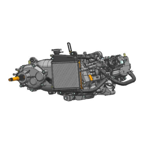
- Page 1 ZT1P52MI Engine maintenance manual 2023-04-01 1/ 42...
- Page 2 All the materials, illustrations, photos, etc. Collected in this manual are compiled according to the latest product of ZT1P52MI Euro IV. However, due to continuous improvement of products and changes in other aspects, there may be some inconsistencies between your motorcycle and this manual. For parts upgrades, please refer to the part codes on the official website of ZONTES which will not be listed in detail in this manual;...
- Page 3 User Notice This manual is compiled by Guangdong TAYO Motorcycle Technology Co., Ltd. And is used to guide dealers or service personnel. This manual cannot provide more detailed knowledge about motorcycles, and is only for reference for maintenance. If you do not have the corresponding knowledge such as electrician, machine repair, etc., improper assembly or maintenance failure may occur during repair.
-
Page 4: Table Of Contents
Table of contents Table of contents ..................4 Spark plug ..................... 6 System components ................. 6 Cylinder compression test ................6 Water pump ................... 7 System components ................. 7 Cylinder head cover, cylinder head ................9 System components ................. 9 Cylinder head cover ................ - Page 5 System components ................40 Crankcase ..................40 5/ 42...
-
Page 6: Spark Plug
Spark plug System components spark plug Remove the spark plug 1. Use the special spark plug socket -16# or the extended socket head -16# to remove the spark plug counterclockwise. Check spark plugs 1. Check the thread of the spark plug and the center electrode. If there is any damage or deformation, replace the spark plug. 2. -
Page 7: Water Pump
②if the measured cylinder pressure is lower than the normal value, pour a small amount of clean engine oil from the spark plug, turn the crankshaft a few times, so that the piston ring and cylinder wall are evenly covered with oil film, and retest the cylinder pressure. - Page 8 Use a flathead screwdriver to pry out the oil seal, and then knock out the bearing to complete the disassembly of the water pump. (note: when the water pump is running normally without failure, it is not recommended Assembly the water pump, internal bearings, oil seals, and water seals.) anointed with oil M6×30 hex flange bolts...
-
Page 9: Cylinder Head Cover, Cylinder Head
4. Put the water-sealed moving ring rubber into the inner hole of the water pump blade; put the water-sealed moving ring into the inner ring of the water-sealed moving ring rubber (the crossed side faces inward, and the smooth side faces outward), and apply an appropriate amount of silicone oil on the smooth surface of the moving ring;... - Page 10 Parts information Name Quantity Name Aym8-m8×38 double-headed 10.9 grade stud Tool: stud socket m8fixed torque: 20±2 N.m (zinc ) Thread fastening glue Tools: 17# socket and fixed torque wrench fixed Water and oil shared sensor torque: 14±1N.m 9×2 EPDM rubber O-ring Tool: 16# spark plug socket fixed torque: 14 ±...
-
Page 11: Cylinder Head Cover
ZT1P58MJ cylinder head Into 2 row ZT1P58MJvalve 13.2×20.8×0.5 valve spring seat Φ 5.0 valve rod diameter oil seal ZT1P58MJ exhaust valve spring Twenty ZT1P58MJ valve spring bearing plate Twenty ZT1P58MJ valve lock clip Twenty M6×10 top pin bolt (zinc) Tool: t-sleeve-8# fixed torque: 10±1N.m three Twenty 6.3×12×1.6 copper gasket... -
Page 12: Cylinder Head
Assembly 1. Use a t-shaped sleeve -8# to remove the thermostat bolts, remove the thermostat, and remove the radiator and fan case cover (refer to the ZT1P52MI engine maintenance manual for disassembly and assembly - thermostat, radiator, fan case cover). -
Page 13: Camshaft
M8×1.25 nut M6×105 bolts Identifier I Camshaft Assembly 1. Remove the cylinder head pressure plate bolts, and take out the cylinder head pressure plate, rocker shaft, intake and exhaust rocker arms, and camshaft. 2. Use the valve spring removal and installation tool to remove the valve lock clip (do not over compress the valve spring). After taking out the valve lock clip, remove the valve spring retainer, valve spring, valve stem diameter oil seal (the removed valve stem diameter oil seal cannot be used again), valve spring seat, and valve in sequence. - Page 14 Install 1. As shown in the figure, install the valve (apply oil), valve spring seat, valve stem diameter oil seal (press in place after installation), valve spring, valve spring retainer, and valve lock clip (install with valve installation tool) in sequence ( note: remove dust and foreign matter from the valve seat surface and cylinder head seat surface.
- Page 15 For the installation of the cylinder piston, refer to the ZT1P52MI engine maintenance manual - cylinder, piston). 2. As shown in the figure, after confirming that there is no missing or wrong installation, install the cylinder head into the corresponding position of the engine.
-
Page 16: Guide Bar
·Tensioner. (refer to ZT1P52MI engine maintenance manual for disassembly and assembly--cylinder head cover, cylinder head-tensioner) ·Cylinder head cover parts. (refer to ZT1P52MI engine maintenance manual for disassembly and assembly--cylinder head cover, cylinder head-cylinder head cover) ·Cylinder head assembly. (refer to ZT1P52MI engine maintenance manual for disassembly and assembly--cylinder head cover, cylinder head-cylinder head) 2. -
Page 17: Tensioner
Tensioner Assembly 1. As shown in the picture, use a cross batch to remove the cross bolts and O-rings on the top of the tensioner, then use the T-bar -8# to evenly loosen the tensioner fixing bolts diagonally, and remove the tensioner and the tensioner pad piece. Inspection 1. -
Page 18: Cylinder, Piston
Cylinder, piston System components Parts information Material name Quantity Remark Cylinder 6.3×12×1.6 copper gasket M6×10 top pin bolt Tool: t-sleeve-8# fixed torque: 10±1 N.m Cylinder head gasket Cannot be reused Cylinder block gasket Cannot be reused Φ 10×14 hollow positioning pin Oil ring combination 16×1 piston pin retaining ring Needle nose pliers... -
Page 19: Cylinder, Piston
Cylinder, piston Assembly 1. Gently pull out the cylinder, and hold the piston and connecting rod with your hands; 2. Remove the piston pin retaining ring with needle-nose pliers, push the piston pin out of the small head hole of the connecting rod, and remove the piston (note: prevent the piston pin retaining ring from falling into the box);... - Page 20 notch " d " of oil ring backing is at "△" on the left side of ex , perpendicular to the line connecting " c " and " e ". (as shown in the picture below) Install the cylinder and piston 1.
-
Page 21: Electric Starter Box Cover, Starter Mechanism, Timing Chain
②the opening of the piston pin retaining ring should avoid the opening of the retaining ring groove by more than 90°. ③piston pin retaining ring is installed in place. ④the direction of the arrow on the top of the piston points to the exhaust side, do not install it backwards. flat sealant Electric starter box cover, starter mechanism, timing chain System components... -
Page 22: Electric Starter Box Cover
151×3 acrylic glue O-ring Cg-78h overrunning clutch Φ19.4 ×φ27.8×3.6 bushing ZT1P58MJ electric starter reduction gear assembly ZT1P58MJ electric starter large gear assembly Tool: t-sleeve-8#. Apply thread glue, fixed M6×10 top pin bolt torque: 12±1.5 N.m ZT1P58MJ guide bar pressure plate Gb276-6804/p5c3 deep groove ball bearings Circlip for non-standard holes φ... -
Page 23: Start Agency
O-ring into the crankshaft and push it in place, and check that there is no misalignment of the oil seal dust lip of the electric starter case cover. Start agency Assembly 1.take out ZT1P58MJ electric starter reduction gear assembly, ZT1P58MJ electric starter reduction gear shaft, CG-78H overrunning clutch, φ... -
Page 24: Oil Pump - Right Crankcase Cover
Note: before removing the timing chain, the ZT1P58MJ radiator subassembly, ZT1P58MJ fan case cover subassembly (rotate the crankshaft clockwise to make the piston at the top dead center), water pump, cylinder head cover, tensioner, and timing sprocket should be disassembled first. Inspection 1. -
Page 25: Right Crankcase Cover
ZT1P58MJ right crankcase cover b Fb22×32×7 fluorine rubber oil seal The oil seal is press-fitted on the right cover ZT1P58MJ right crankcase cover gasket Φ 10×14 hollow positioning pin M5×15-5# hexagon socket head screw (oxidized black) Apply thread glue. Fixed torque: 5±1 N.m When the oil pump is installed, it is necessary ZT1P58MJ oil pump parts to inject an appropriate amount of oil into the... -
Page 26: Oil Filter
Inspection 1. The oil pump rotor and oil pump teeth are not abnormally worn. Install 1. Inject an appropriate amount of oil into the rotor of the oil pump, place the oil pump gasket at the corresponding position of the oil pump, then place the oil pump at the corresponding position of the right crankcase, take 2 m5×15-5 # inner hexagonal cylindrical screws and apply an appropriate amount of thread glue, after screwing in, tighten with a fixed torque, torque: 5±1N.m. -
Page 27: Oil Filter
Φ 18.5×13×1.6 oil filter spring Outer diameter φ 44×40 cylindrical oil filter ZT1P58MJ oil filter seal ring Can not be missing Oil filter Assembly 1. Remove the locking bolt of the oil filter cover with a t-shaped sleeve -10#, and take out the ZT1P58MJ oil filter cover (ceramic), φ... -
Page 28: Magneto Rotor
Material name Quantity Remark Stator pressure plate Trigger Waterproof rubber sleeve Magneto stator Apply thread glue, inner hexagon tip -5#, fixed Gb70.1m6×25 (zinc) torque: 10±1n m Apply thread glue, external hexagon socket-8#, M6×16 hex flange bolts fixed torque: 12±1.5n m ZT1P58MJ magneto rotor parts 12.5×23×1.8 gasket M12×1.25 hexagonal flange surface 10 grade nuts (zinc) -
Page 29: Magneto Stator
Sensing point 2. Put the fan on the corresponding position of the flywheel, apply an appropriate amount of thread fastening glue on the three GB5789 M6×16 threads, and tighten with t-sleeve -10#, torque standard: 10±1N.m. Magneto stator Assembly Use a torque wrench (or air batch), inner hexagonal gun head-5# and outer hexagonal sleeve-8# to fix the 3 GB70.1 M6×25 bolts on the coil, the 3 bolts on the trigger pressure plate and the stator pressure plate. -
Page 30: Left Crankcase Cover, Continuously Variable Clutch Sub-Assembly
Part name Quantity Part name Quantity ZT1P52MI slope plate M6×60 hexagonal flange bolts (zinc) M6×30 hexagonal flange bolts (zinc) ZT1P52MI v-shaped transmission belt M12×1.25 hexagonal flange surface 10 grade ZT1P52MI buffer slider nuts (zinc) Φ21.8×φ1.8 acrylic O-ring ZT1P52MI centrifugal roller ZT1P52MI... -
Page 31: Continuously Variable Clutch Sub-Assembly
φ12.2×φ29×2.5 gasket, 12×24×2.6 butterfly shaped spring washer and φ12.8×φ25×16.7 driven wheel bushing, then remove the positioning fixture for the driving and driven wheels, remove the ZT1P52MI main fixed plate from the crankshaft, and remove the driven wheel clutch jacket from the drive shaft. Pinch the middle part of the V-shaped driving belt, and remove the belt and driven wheel sub-assembly together. - Page 32 bushing with the other hand to align the inner hole of the driving wheel bushing with the crankshaft. Then the slope plate, the centrifugal roller, the main sliding wheel sub-components, and the driving wheel bushing are combined and assembled on the crankshaft as a whole and withstand the φ...
-
Page 33: Gearbox
6.2×19×2.5 spacers bearings (koyo) Gb276-6302/p5c3 deep groove ball Gb5789m6×12 (zinc) bearings (nitrided) Fb35×54×7 fluorine rubber oil seal ZT1P58MJ drive shaft ZT1P58MJ output shaft ZT1P52MI double gear subassembly Gb894.1 shaft circlip φ25 ZT1P52MI output gear Gb276-6304/p5c3 deep groove ball bearing 33/ 42... - Page 34 Bolt torque value: Bolt model Assembly position Quantity Torque ( N.m ) Remark Gb16674m8×40 (zinc) Gear case cover locking bolt 20±2.5 Apply thread Gb5789m6×12 (zinc) 6204 bearing platen bolts 1 0 ± 1 glue Non-standard bolt m8×25 (zinc) Gearbox oil drain bolt 20±2.5 34/ 42...
-
Page 35: Gear Case Cover
Then remove the output gear, duplex gear assembly, output shaft and output shaft retaining ring in sequence. Retaining ring mounting output gear ZT1P52MI double gear Output shaft Inspection 1. Check the gear case cover bearing and oil seal. Turn the inner ring of the bearing by hand, and the bearing turns smoothly and silently. - Page 36 4. Check the spline position of the drive shaft and output shaft to see if there is any bending deformation or abnormal wear. If so, please replace it. (note: if there is no abnormality in the drive shaft, it is not recommended to take it out from the left box. Taking it out will damage the 6204 bearing;...
- Page 37 Maintenance Oil volume Routine maintenance (without 160ml disassembling the gearbox) Gearbox oil Non-routine maintenance (disassembly 170ml of gearbox) 3. After the assembly is completed, wipe off the oil stains around the gear case cover. 37/ 42...
-
Page 38: Thermostat, Radiator , Fan Case Cover
Thermostat, radiator , fan case cover System components Material name Quantity ZT1P58MJ thermostat subassembly 16.5×1.95 EPDM o -ring ZT1P58MJ right crankcase parts ZT1P58MJ fan box cover subassembly M6×60 hexagonal flange bolts (zinc) ZT1P58MJ radiator subassembly GB5789 M6×35 (zinc) 38/ 42... -
Page 39: Thermostat, Radiator, Fan Case Cover
Thermostat, radiator, fan case cover Assembly M6×22 hexagonal flange bolts that lock the thermostat; 2. Use clamp pliers to remove the hoop connected to the radiator, remove the water pipe, use t-shaped sleeve -10# to remove the four GB5789 M6 ×35 bolts that fix the radiator, and remove the radiator. (note: take care to protect the radiator fins from being damaged);... -
Page 40: Crankcase
Crankcase System components Parts information Name Quantity ZT1P58MJ left crankcase parts (short wheelbase version) ZT1P58MJ crankshaft connecting rod parts ZT1P58MJ right crankcase parts Φ10×14 hollow positioning pin M6×60 hexagonal flange bolts (zinc) M6×105 hexagonal flange surface 9.8 grade bolts (zinc) Crankcase Assembly M6×60 hexagonal flange bolts (zinc) and 3 m6×105 hexagonal flange surface 9.8 grade bolts (zinc) on the right crankcase side). - Page 41 To tap symmetrically on the reinforcement hole of the right crankcase or the process boss to separate the left and right crankcases evenly, and take out the crankshaft and the right crankcase together. And take out the positioning pin together (note: do not hit the joint surface of the crankcase or other assembly joint surfaces;...
- Page 42 M6×105 hexagon flange face 9.8 grade M6×60 hex flange bolts M8×25 42/ 42...
Need help?
Do you have a question about the ZT1P52MI and is the answer not in the manual?
Questions and answers