Table of Contents
Advertisement
Quick Links
GETTING STARTED GUIDE
NI USRP -29xx
This document explains how to install, configure, and set up the National Instruments
Universal Software Radio Peripheral (USRP) 2920, 2921, 2922, 2930, or 2932 (NI 29xx)
device. The NI USRP-29xx is a software-defined radio (SDR), which can send and receive
signals for use in communications applications. This device ships with the NI-USRP instrument
driver, which you can use to program the device.
For more information about device features, programming, and examples, refer to the NI-USRP
Help at Start»All Programs»National Instruments»NI-USRP»Documentation»NI-USRP
Help. Individual device specifications are available at Start»All Programs»National
Instruments»NI-USRP»Documentation»Specifications.
For the most current versions of product documents, visit
version of NI-USRP driver software, visit
Quick Start Steps
The following steps are an overview of the NI USRP-29xx getting started process. Follow these
steps to use the NI USRP-29xx after you install LabVIEW on your computer:
1.
Install the NI USRP Software Suite DVD. The software suite adds the following items to
your LabVIEW installation: the NI-USRP driver, LabVIEW Modulation Toolkit,
LabVIEW MathScript RT Module, and LabVIEW Digital Filter Design Toolkit. For more
information, refer to section
2.
Connect the Device. Attach the antenna or cable to the front of the NI USRP-29xx device.
Connect the device directly to your computer with the enclosed Ethernet cable and connect
the power. For more information, refer to section
Hardware
on page 6.
3.
Change the IP address of your 1 Gigabit Ethernet Port to a static IP. NI recommends
a static IP address of 192.168.10.1 because NI USRP-29xx devices have a default address
of 192.168.10.2. For more information, refer to section
Hardware
on page 6.
4.
Run an example. Examples are located in LabVIEW. Navigate to the Functions Palette
and select Start»All Programs»National Instruments»NI-USRP»Examples. For more
information, refer to section
5.
Update the firmware using the NI-USRP Configuration Utility. Select Start»
All Programs»NI-USRP»NI-USRP Configuration Utility to open the NI-USRP
Configuration Utility. For more information, refer to section
and FPGA Images
If you have trouble with any of these steps, refer to the detailed sections of this guide or the video
at
ni.com/usrp/gettingstarted/
December 2012
375717D-01
™
ni.com/updates
4. Installing the Software
6. Programming the NI 29xx
on page 12.
.
ni.com/manuals
.
on page 5.
5. Installing and Configuring the
5. Installing and Configuring the
on page 11.
7: Updating Device Firmware
. For the latest
Advertisement
Table of Contents

Summary of Contents for National Geographic USRP-29 Series
- Page 1 GETTING STARTED GUIDE ™ NI USRP -29xx This document explains how to install, configure, and set up the National Instruments Universal Software Radio Peripheral (USRP) 2920, 2921, 2922, 2930, or 2932 (NI 29xx) device. The NI USRP-29xx is a software-defined radio (SDR), which can send and receive signals for use in communications applications.
-
Page 2: Table Of Contents
Electromagnetic Compatibility Guidelines This product was tested and complies with the regulatory requirements and limits for electromagnetic compatibility (EMC) as stated in the product specifications. These requirements and limits are designed to provide reasonable protection against harmful interference when the product is operated in its intended operational electromagnetic environment. -
Page 3: Verifying The System Requirements
NI USRP-2922........................20 NI USRP-2930........................22 NI USRP-2932........................25 Appendix B: Network Troubleshooting ................... 28 The Device Does Not Connect to the Host Ethernet Interface......... 28 The Device Does Not Respond to a Ping (ICMP Echo Request)........28 The NI-USRP Configuration Utility Does Not Return a Listing for My Device..... 28 The Device IP Address Does Not Reset to the Default ............ -
Page 4: Verifying The Kit Contents
3. Verifying the Kit Contents Verify that the kit contains the following items required to set up and use the device: Driver software media—Installs the NI-USRP driver software and electronic documentation, including the NI-USRP Help, the NI-USRP Readme, and device specifications. -
Page 5: Optional Items
Optional Items LabVIEW Modulation Toolkit (MT), included on the NI-USRP instrument driver software media, which includes MT VIs and functions, examples, and documentation You must install the LabVIEW Modulation Toolkit for proper operation of Note the NI-USRP Modulation Toolkit example VIs. ... -
Page 6: Installing And Configuring The Hardware
5. Installing and Configuring the Hardware Install all the software you plan to use with the hardware before installing the hardware. The device connects to a host computer using a standard gigabit Ethernet interface. Refer to the documentation for your gigabit Ethernet interface for installation and configuration instructions. Installing NI 29xx Devices Use the Ethernet cable to connect the device to the computer. -
Page 7: Confirming Network Connection
NI-USRP uses user datagram protocol (UDP) broadcast packets to locate Note the device. On some systems, the firewall blocks UDP broadcast packets. NI recommends that you change or disable the firewall settings to allow communication with the device. Make sure the host computer is using a static IP address. You may need to modify the network settings for the local area connection using the Control Panel on the host computer. -
Page 8: Configuring Multiple Devices
Utility does not return a listing for your device, refer to Appendix B: Network Troubleshooting for information about troubleshooting the network connection. Configuring Multiple Devices You can connect multiple devices in the following ways: • Multiple Ethernet interfaces—One device for each interface •... - Page 9 multiple USRP devices connected to the switch. Assign the host Ethernet interface a subnet, and assign each device an address in that subnet, as shown in the following table. Table 3. Single Host Ethernet Interface—Unmanaged Switch Configuration Host Host Device Device IP Address Subnet Mask...
-
Page 10: Changing The Ip Address
Changing the IP Address To change the NI 29xx device IP address, you must know the current address of the device, and you must configure the network as described in the Default IP Address section. Verify that your device is powered on and connected to your computer using the gigabit Ethernet interface. -
Page 11: Programming The Ni 29Xx
The utility displays a confirmation to indicate the process is complete. Click OK. Figure 3. IP Address Changed Power cycle the device to apply the changes. After you change the IP address, you must power cycle the device and click Note Find Devices in the utility to update the list of devices. -
Page 12: 7: Updating Device Firmware And Fpga Images
7: Updating Device Firmware and FPGA Images USRP devices contain firmware and FPGA images that provide compatibility with driver software. The NI 29xx devices ship with firmware and FPGA images compatible with NI-USRP driver software. You may need to update the device for compatibility with the latest version of the software. - Page 13 The utility updates the firmware and FPGA images in a single operation. Verify that the firmware and FPGA image paths are entered correctly. The utility should appear similar to Figure 4. Figure 4. N2xx/NI-29xx Image Updater NI USRP-29xx Getting Started Guide | © National Instruments | 13...
- Page 14 Click the Find Devices button to scan for USRP devices and update the device list. If your device does not appear in the list, verify that the device is on and correctly connected to the computer. If your device still does not appear in the list, you can manually add the device to the list. Click the Manually Add Device button, enter the IP address of the device in the dialog box that displays, and click OK.
-
Page 15: Updating Usrp2 Firmware And Fpga Images
13. Verify that the D LED is lit on the device front panel to confirm that the firmware and FPGA images loaded successfully. Refer to the Load the images onto the on-board flash (USRP-N Series only) section of the UHD - USRP2 and N Series Application Notes at files.ettus.com/uhd_docs/manual/ for more information about updating the USRP N2xx device firmware and html/usrp2.html... - Page 16 Verify that the firmware and FPGA image paths are entered correctly, as the utility updates both files in the same operation. The utility should appear similar to Figure 6. Figure 6. USRP2 SD Card Burner Click the Refresh Device List button, and select the drive letter that corresponds to the SD card interface connected to your computer.
-
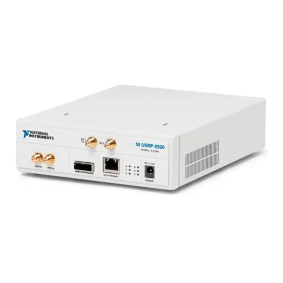
Page 17: Appendix A: Front Panels, Backplanes, And Connectors
Appendix A: Front Panels, Backplanes, and Connectors NI USRP-2920 Figure 7. NI USRP-2920 Front Panel NI USRP - 2920 RX 1 RX 2 TX 1 50 MHz - 2.2 GHz REF IN PPS IN MIMO EXPANSION GB ETHERNET POWER Table 4. NI USRP-2920 Module Front Panel Connectors Connector RF signal input and output terminal. - Page 18 Table 5. NI USRP-2920 Module LEDs Indication Indicates the transmit status of the NI USRP-2920 module: OFF—The module is not transmitting data. GREEN—The module is transmitting data. Indicates the status of the physical MIMO cable link: OFF—The modules are not connected using the MIMO cable. GREEN—The modules are connected using the MIMO cable.
-
Page 19: Ni Usrp-2921
NI USRP-2921 Figure 8. NI-2921 Front Panel NI USRP - 2921 RX 1 RX 2 TX 1 TX 2 2.4 - 2.5 GHz, 4.9 - 5.85 GHz REF IN PPS IN MIMO EXPANSION GB ETHERNET POWER Table 6. NI USRP-2921 Module Front Panel Connectors Connector RF signal input and output terminal. - Page 20 Table 7. NI USRP-2921 Module LEDs Indication Indicates the transmit status of the NI USRP-2921 module: OFF—The module is not transmitting data. GREEN—The module is transmitting data. Indicates the status of the physical MIMO cable link: OFF—The modules are not connected using the MIMO cable. GREEN—The modules are connected using the MIMO cable.
-
Page 21: Ni Usrp-2922
NI USRP-2922 Figure 9. NI USRP-2922 Front Panel NI USRP - 2922 RX 1 RX 2 TX 1 400 MHz - 4.4 GHz REF IN PPS IN MIMO EXPANSION GB ETHERNET POWER Table 8. NI USRP-2922 Module Front Panel Connectors Connector RF signal input and output terminal. - Page 22 Table 9. NI USRP-2922 Module LEDs Indication Indicates the transmit status of the NI USRP-2922 module: OFF—The module is not transmitting data. GREEN—The module is transmitting data. Indicates the status of the physical MIMO cable link: OFF—The modules are not connected using the MIMO cable. GREEN—The modules are connected using the MIMO cable.
-
Page 23: Ni Usrp-2930
NI USRP-2930 Figure 10. NI USRP-2930 Front Panel NI USRP-2930 RX 1 RX 2 TX 1 50 MHz - 2.2 GHz REF IN PPS IN MIMO EXPANSION GB ETHERNET POWER Table 10. NI USRP-2930 Module Front Panel Connectors Connector RF signal input and output terminal. RX1 TX1 is an SMA (f ) connector with an impedance of 50 Ω... - Page 24 Table 11. NI USRP-2930 Module LEDs Indication Indicates the transmit status of the NI USRP-2930 module: OFF—The module is not transmitting data. GREEN—The module is transmitting data. Indicates the status of the physical MIMO cable link: OFF—The modules are not connected using the MIMO cable. GREEN—The modules are connected using the MIMO cable.
- Page 25 Figure 11. NI USRP-2930 Backplane Table 12. NI USRP-2930 Module Backplane Connector Connector GPS ANT Input terminal for the GPS antenna signal SMA (f) with 50 Ω impedance. NI USRP-29xx Getting Started Guide | © National Instruments | 25...
-
Page 26: Ni Usrp-2932
NI USRP-2932 Figure 12. NI USRP-2932 Front Panel NI USRP-2932 RX 1 RX 2 TX 1 400 MHz - 4.4 GHz REF IN PPS IN MIMO EXPANSION GB ETHERNET POWER Table 13. NI USRP-2932 Module Front Panel Connectors Connector RF signal input and output terminal. RX1 TX1 is an SMA (f ) connector with an impedance of 50 Ω... - Page 27 Table 14. NI USRP-2932 Module LEDs Indication Indicates the transmit status of the NI USRP-2932 module: OFF—The module is not transmitting data. GREEN—The module is transmitting data. Indicates the status of the physical MIMO cable link: OFF—The modules are not connected using the MIMO cable. GREEN—The modules are connected using the MIMO cable.
- Page 28 Figure 13. NI USRP-2932 Backplane Table 15. NI USRP-2932 Module Backplane Connector Connector GPS ANT Input terminal for the GPS antenna signal SMA (f) with 50 Ω impedance. 28 | ni.com | NI USRP-29xx Getting Started Guide...
-
Page 29: Appendix B: Network Troubleshooting
Appendix B: Network Troubleshooting The Device Does Not Connect to the Host Ethernet Interface The host Ethernet interface must be a gigabit Ethernet interface to connect to the USRP device. Ensure the connection between the host network interface card and the device cable connection is valid and both the device and computer are powered on. -
Page 30: Appendix C: Compliance And Certifications
Continue to press the safe-mode button until the front-panel LEDs blink and remain solid. While in safe-mode, run the NI USRP Configuration Utility to change the IP address from the default, , to a new value, as described in the Changing the IP Address 192.168.10.2 section. -
Page 31: Ce Compliance
In the United States (per FCC 47 CFR), Class A equipment is intended for use Note in commercial, light-industrial, and heavy-industrial locations. In Europe, Canada, Australia and New Zealand (per CISPR 11) Class A equipment is intended for use only in heavy-industrial locations. Group 1 equipment (per CISPR 11) is any industrial, scientific, or medical Note equipment that does not intentionally generate radio frequency energy for the... -
Page 32: Appendix D: Where To Go For Support
Appendix D: Where to Go for Support The National Instruments website is your complete resource for technical support. At ni.com/ you have access to everything from troubleshooting and application development support self-help resources to email and phone assistance from NI Application Engineers. A Declaration of Conformity (DoC) is our claim of compliance with the Council of the European Communities using the manufacturer’s declaration of conformity.
Need help?
Do you have a question about the USRP-29 Series and is the answer not in the manual?
Questions and answers