
Related Manuals for IVAC Pro Switch DEC


Summary of Contents for IVAC Pro Switch DEC
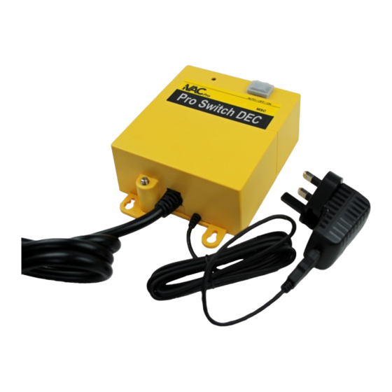
- Page 1 Product variations exist. For illustration only. Read this handbook before installation & use - retain for future reference...
- Page 2 The user must analyse all aspects of the application, follow applicable industry standards, and follow the information concerning the product in the current product catalog and in any other materials provided from iVAC or its subsidiaries or authorised distributors.
-
Page 3: Table Of Contents
Contents iVAC Pro Switch DEC (Dust Extractor Controller) – Overview (page 4) User Operation (page 5) Warnings - User Operation Pro Switch function Mode Switch (AUTO, OFF or ON) AUTO Mode - Operation process LED Indicator Functional features explained Physical Features Configuration –... -
Page 4: Ivac Pro Switch Dec (Dust Extractor Controller) - Overview
This Handbook covers the Operation, Configuration and Installation of the iVAC Pro Switch DEC (Dust Extractor Controller). The iVAC Pro Switch DEC is the component within the iVAC Pro System that is used to control your Dust Extractor. Installation and operation is simple and easy as the iVAC Pro Switch DEC communicates with all other Pro System components wirelessly –... -
Page 5: User Operation
Pro Switch function The iVAC Pro Switch is the component of the iVAC wireless Pro System that is used to control your Dust Extractor - e.g. turn it ON or OFF. Mode Switch – 3 position rocker The Mode switch is manually set to AUTO, OFF or ON. -
Page 6: Auto Mode - Operation Process
AUTO Mode - Operation process When set to AUTO, The Pro Switch receives and processes wireless ON / OFF commands from iVAC Remotes and Tool Plus's. The Pro Switch records these ON / OFF commands into it's memory in preparation for... -
Page 7: Functional Features Explained
Functional Features Explained 2.6.1 Turn ON Delay Time The Turn On Delay is to avoid two start-up power surges occurring at the same time on a supply circuit that is feeding both the Power Tool and the Dust Extractor. This function is to avoid tripping the main circuit breaker (overloading). The Turn On Delay time is factory set to 1.5 seconds. - Page 8 2.6.7 Power Failure Protection (NVR - No Voltage Release) The Pro Switch will help to ensure that in the event of a power failure, your Extractor does not start up automatically when power is reinstated. The Pro Switch has a safety feature that prevents the Extractor turning ON if the mode switch is set to ON or AUTO when USB power is applied How this works depends on the position of the Mode Switch when the power failure occurred:...
-
Page 9: Physical Features
Physical Features Product variations exist. For illustration only. Access panel to DIP switches. Earth (ground) terminal. Located on the rear of the Can be used to earth enclosure. PH1 screwdriver equipment and ducting. required. 9 of 20 DEC handbook (5 wire) MJA R14... - Page 10 Switch's memory when the Mode Switch is in the OFF position OR when the Pro Switch power (USB) is removed. Once you have configured your Pro Switch and related iVAC components, you can apply the labels from the supplied sheet. Labelling your iVAC components helps identify them for future reference.
-
Page 11: System Id (Address)
System ID (Address) There are four System ID's (Addresses), this enables up to four iVAC systems to operate independently while within the same workshop (e.g. Within communication range of each other). Typically one Pro Switch controls one Extractor. The Pro Switch can be assigned to work on one of the four System ID's (Addresses) - A, B, C or D. -
Page 12: Turn Off Time Delay And Minimum Run Time
Turn OFF Time Delay and Minimum Run Time 3.3.1 Turn OFF Time Delay This feature is to allow the Dust Extractor to continue to run after a power tool has been turned OFF, clearing up any remaining debris at the power tool and in the ducting. -
Page 13: Installation
4.1.1 Please read this Handbook before installation and use. Retain for future reference. 4.1.2 The iVAC Pro Switch is intended for indoor use, in dry locations only. 4.1.3 The iVAC Pro Switch should only be powered by the supplied USB 5V DC Power Supply. -
Page 14: Electrical Connections - General Information
Black and Green pair, connected to relay 2 (NO contacts) • Green / Yellow, Earth (ground) The two relays within the Pro Switch DEC are always switched together - they are both either ON or OFF. • The relay contacts are closed to provide power to the Dust Extractor. -
Page 15: Relay Wiring - Illustration & Explanation
Relay Wiring – Illustration & Explanation The 4 switching wires of the Pro Switch are connected to the two relays within the Pro Switch. Each relay has one set of Normally Open (NO) Contacts. Relay one NO / SP 6.5A 230VAC 28VDC Relay two... -
Page 16: Connection Options
4.7 for further information Direct Switching (single phase motors only) The Pro Switch DEC can be used to control a Dust Extractor motor by means of it's two relays. The relay contacts can switch the power to the Extractor motor. - Page 17 4.6.1 Single Pole (maximum power – 3Kw / 230V) When connected in parallel, the two relays can be used to switch only the Live power lead to the Dust Extractor motor. In this configuration, 230V Dust Extractors up to 3000 watts (3HP) can be controlled. For guidance only - always consult an expert 4.6.2 Double Pole (maximum power –...
-
Page 18: Digital Input Control (E.g. Vfd Motor Drive)
Dust Extractors with electronic controllers (e.g. VFD / Motor Drive) can usually be controlled by means of a digital signal input or contact closure. The Pro Switch DEC could be connected to a VFD as shown in the example below. For guidance only - always consult an expert In this situation, typically only one wire pair (one relay) from the Pro Switch is required. -
Page 19: Warranty
Service and Repairs Your iVAC Pro Switch will give many years of reliable service. In the event of damage or a fault you can return the Pro Switch to our UK workshop for repair. -
Page 20: Contact
8.0 Contact United Kingdom - Toolovation www.toolovation.co.uk ivac@toolovation.co.u k 01531 636819 Canada (head office) - iVAC www.ivacswitch.com info@ivacswitch.com 20 of 20 DEC handbook (5 wire) MJA R14...
Need help?
Do you have a question about the Pro Switch DEC and is the answer not in the manual?
Questions and answers