
Related Manuals for Japan Radio Co. JMA-5212-4


Summary of Contents for Japan Radio Co. JMA-5212-4
- Page 1 JMA-5212-4/6 JMA-5212-4/6 JMA-5222-7/9 JMA-5222-7/9 JMA-5212-4HS/6HS JMA-5212-4HS/6HS MARINE RADAR MARINE RADAR EQUIPMENT EQUIPMENT FIELD SERVICE FIELD SERVICE MANUAL MANUAL...
-
Page 3: Table Of Contents
2.5.5. T/R Control Circuit CMC-1205R..................2-21 Chapter 3_Service Parts 3.1. Service Parts Lists for the Units ..................... 3-1 3.1.1. Spare Parts ........................3-1 3.1.2. Special Parts ........................3-2 3.1.3. NKE-2103 (JMA-5212-4/6/4HS/6HS)................3-2 3.1.4. NKE-2254 (JMA-5222-7/9)....................3-3 3.1.5. NCD-4380 ........................3-3... - Page 4 3.2. Exploded Diagrams........................ 3-4 3.2.1. NKE-2103 ........................3-4 3.2.2. NKE-2254 ........................3-8 3.2.3. NDC-1460 ........................3-12 3.2.4. NCE-7699A........................3-16 Chapter 4_Replacement of Major Units 4.1. Scanner Unit .......................... 4-1 4.1.1. Precautions for replacing parts in the scanner unit ............4-1 4.1.2.
- Page 5 4.2.9. Operation Circuit CCK-979 for the Standard Operation Unit ......... 4-47 4.2.10. PS2 Connector Circuit CQC-1204 for the Standard Operation Unit ......4-49 4.2.11. Trackball TRD-101S(BK)N1 for the Standard Operation Unit........4-51 Chapter 5_Program Update 5.1. Main Program Update Procedure................... 5-1 5.1.1.
- Page 6 Outline Drawing of the Rectifier NBA-5111 (Option)............7-10 7.2. System Diagrams........................7-11 7.2.1. Overall System Diagram of the Radar JMA-5222-7/9 ............7-11 7.2.2. Overall System Diagram of the Radar JMA-5212-4/6/4HS/6HS ........7-12 7.3. Inter-Unit Connection Diagram..................... 7-13 7.3.1. Inter-Unit Connection Diagram of the JMA-5222-7/9 ............ 7-13 7.3.2.
-
Page 7: Chapter 1_Equipment Overview
Chapter 1 Equipment Overview... -
Page 9: Overview
1.1. Overview This equipment is marine radar equipment satisfying the IMO standard. The radar equipment consists of a scanner unit that generates transmitting signals, transmits and receives radio waves, and amplifies receiving signals, and a display system that displays radar images after removing unwanted radio wave from the radar signals. The radar equipment with which a magnetron tube is used as the transmitting tube transmits 9.4 GHz (X band) pulse-modulated waves. -
Page 10: Display System
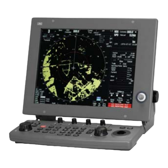
1.3. Display System The display system processes a radar signal transmitted from the scanner unit, removes unwanted radio wave, and plots/displays radar images in a specified observation range. The user is to stand in front of the display system and observe the conditions around the own ship with the radar images displayed on the display unit by operating the switches and trackball on the operation unit. -
Page 11: Chapter 2_Equipment Overview
Chapter 2 Equipment Overview... -
Page 13: Configuration
2.1.1. Scanners and Transmitted Output Powers IMO compliance MODEL TRANSMITTED RATE OF SCANNER BAND CATEGORY NUMBER OUTPUT POWER ROTATION JMA-5212-4 4 FT SLOT ANTENNA 10kW 27rpm CAT 2 JMA-5212-6 6 FT SLOT ANTENNA 10kW 27rpm CAT 2 JMA-5222-7 7 FT SLOT ANTENNA... -
Page 14: Radar Configuration And Ship's Mains
2.1.2. Radar Configuration and Ship's Mains IMO compliance MODEL PERFORMANCE DISPLAY SCANNER SHIP'S MAINS NUMBER MONITOR UNIT SYSTEM JMA-5212-4 NKE-2103-4 NJU-85 NCD-4380 DC24V JMA-5212-6 NKE-2103-6 NJU-85 NCD-4380 DC24V JMA-5222-7 NKE-2254-7 NJU-85 NCD-4380 DC24V JMA-5222-9 NKE-2254-9 NJU-85 NCD-4380 DC24V Non IMO compliance... - Page 15 (Notes) A deicing mechanism (neck heater) is optional. "D" is suffixed to the model number of a scanner unit with a deicing mechanism. Keep in mind that only power supply of 100-115 VAC, 50/60 Hz and single phase is applicable to the neck heater and that a deicing mechanism cannot be installed in the NKE-2103.
-
Page 16: Power System Diagram
2.2. Power System Diagram Figure 2.1 Power System Diagram... - Page 17 Figure 2.1 shows the power system diagram of this equipment. DC power passes through the circuit breaker via the line filter in the power circuit CBD-1702A, and it is re-input to the power circuit CBD-1702A for generating the supply voltage to be used inside the equipment. The power circuits are of the high-efficiency switching type.
- Page 18 2.3. Functional System Diagram 2.3.1. Scanner Unit NKE-2254 Scanner Unit SLOT ANTENNA ROTARY MOTOR A, B, Z ENCODER JOINT B101 FILTER DIODE LIMITER V101 RECEIVER PULSE Tune Control RF AMP TRANS DUMMY LOAD Receiver Bandwidth SWITCHING Control IF AMP CIRCUIT PC201 Tx Trigger/Pulse Width VIDEO...
-
Page 19: Display System
Figure 2.2 shows the functional system diagram of the scanner unit for this equipment. When the power relay for the scanner unit in the display system is turned on and power is supplied to the scanner unit, the power circuit starts power supply to each circuit of the scanner unit. - Page 20 The received radar video signal, transmission timing signal, and antenna rotation signal are sent to the display system. The radar video signal is a non-processed, log-compressed signal. The antenna rotation signal is an incremental signal, and 2048 rotation pulses and reference bearing pulses per cycle are used.
Need help?
Do you have a question about the JMA-5212-4 and is the answer not in the manual?
Questions and answers