Table of Contents
Advertisement
Quick Links
HESHBON Wheel Balancer
Installation/Operation & Maintenance Manual
HW-105
Before use, read and understand this manual thoroughly. "Safety Cautions" are established to keep your
safe and prevent damages on properties, so you are wanted to read them carefully. The manual may be
changed without any prior notice for quality improvement.
Advertisement
Table of Contents

Summary of Contents for HESHBON HW-105
- Page 1 HESHBON Wheel Balancer Installation/Operation & Maintenance Manual HW-105 Before use, read and understand this manual thoroughly. "Safety Cautions” are established to keep your safe and prevent damages on properties, so you are wanted to read them carefully. The manual may be...
- Page 2 The copyright on this manual is exclusively owned by Heshbon Co.,Ltd Therefore, it is strictly prohibited to illegally reproduce this manual and use any part of this manual without permission. Registration No.: 105090301A Copyringht Heshbon Co.,Ltd. MIT Design Group 2009 All rights reserved.
-
Page 3: Table Of Contents
TABLE OF CONTENTS Introduction Features Parts' Names Positions of Name Plate and Labels Functions of Control Panel Specification Safety Cautions Danger/Warning/Caution Installation Transportation and installation Application Modes according to wheel types Dynamic Mode ALU -S Special ALU function Split function Self-Calibration Function Setting Accessing Menus... -
Page 4: Features
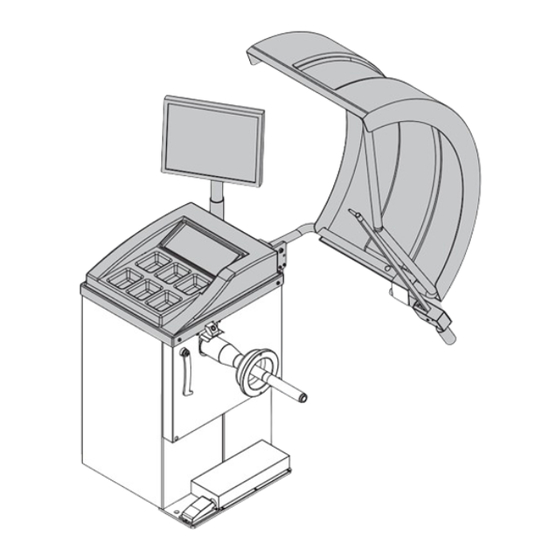
Introduction Heshbon Wheel Balance features the followings. Features Introduction Monitor Wheel guard Cone Hanger Work table Length, diameter and width auto- matically entered ■ Various modes to balance wheels ▶Various modes are supported so that tire wheel can be facilitated conveniently and easily. - Page 5 Heshbon Wheel Balance features the followings. Introduction ■ Weight separation for aluminum wheel ▶Unbalanced position on an aluminum wheel’s outer plane is divided into two parts, enabling lead weights to be applied behind two wheel spokes. Introduction ① Width gauge ■...
-
Page 6: Parts' Names
Introduction Parts' names Introduction ■Monitor ■Control Panel ■Work Table ■Adaptor and Accessories Support ■Main S/W... - Page 7 Introduction ■Laser Pointer (option) Introduction ■Wheel Guard (option) ■Shaft ■Automatic Width Gauge(option) ■Automatic Gauge Arm ■Electrical Input Switch (break pedal-option)
-
Page 8: Positions Of Name Plate And Labels
Introduction Positions of name plate and labels Introduction ■Warning Sign(Cover) ■Product Identification plate ■Warning Sign ■Operator's Manual Ref- erence Mark... - Page 9 Introduction Introduction ■Heshbon Logo ■Warning Sign(Feet)
-
Page 10: Functions Of Control Panel
Introduction Functions of Control Panel ■ Name Introduction ①Cut ②Cal ③Position ④Special ⑤Divide ⑥Menu ⑦Enter ⑧L ⑨W ⑩D ⑪Start ⑫Stop ■ Functions ①Cut - Button used to check the left weight amount ②Cal - Press if to run Self-Calibration ③Position - Automatically stop on an unbalanced position of the wheel measured(optional) ④Special - Measure a special aluminum wheel ⑤Divide - Split function. -
Page 11: Specification
Introduction Specification Model HW-105 Measuring method Both sides(In/Out) at the same time Measuring unit 1g (both sides) Introduction Measuring time 7 ~ 12sec Distance 0~18cm Rim Width 1.5"~20" Measuring range Rim diameter 10" ~24" Weight 65kg Balancing speed Approx 200rpm... - Page 12 Safety Cautions Danger/Warning/Caution A user may be injured or even dead unless Illustrations throughout this manual the directions are kept. About illustrations Not keeping the directions may result in used in this manual It will help you under- serious injuries or damages on properties. stand this manual and please read it carefully.
-
Page 13: Safety Cautions
Safety Cautions Be cautious that Do not insert Make sure that fingers may be multiple plugs on electric contacts/ Read this manual hurt by the rotating an outlet. pins should be carefully before shaft. ▶ It may cause an maintained clean. use. -
Page 14: Installation
Installation Transportation and installation Transportation ▶Upon arrival at an installa- tion place, move this package to an installation location using a forklift or truck. ▶Unpack and check the com- ponents in the package. If any missing component is found, immediately contact your deal- er or the company. - Page 15 Installation Transportation and installation Installation ▶Check the effectiveness of the ground/earth connection. ▶The machine must be connected to the supply through a multi-pole cut-off switch in conformity with European standards and with contact opening gap of at least 3 mm. ▶When connected and switched on, mounted wheels must rotate in a clockwise direction as seen from the...
-
Page 16: Application
Application Modes according to Wheel Types From the measurement screen, press button ALU to select the type required. The 5-LED displays show the position where to apply the weights. If a spin has al- ready been performed, the processor automatically re- calculates, for each change of mode, the amounts os unbalance according to the new calculation. - Page 17 Application DYNAMIC applicable to general wheels ▶ Power supply Switch on the machine with the main switch. Tire wheel placement Mount the wheel on the machine, centering it on the relevant cone or adaptor and tighten it carefully with the quick-nut. Enter rim parameters 3.1 Automatic rim Distance (offset) and Diameter - Move the automatic gauge arm to the inside edge of...
- Page 18 Application DYNAMIC ▶ CORRECTION OF THE UNBALANCE Closing Wheel guard Spin the wheel by lowering the wheel guard or by pressing the Start but- ton. When the balancing cycle is completed the wheel will stop auto- matically and the unbalance values will appear on the monitor.
- Page 19 Application Correcting INNER values Correct the inner plane in the same manner. Verification of the results Lower the wheel guard to spin the wheel again and check that the readout is “00” “00”(OK message will appear in the screen). If a residual imbalance is displayed: A.
-
Page 20: Alu -S Special Alu Function
Application ALU -S Special ALU function This is a mode similar to ALU mode 2. The difference is that the distance and width parameters are accurately defined for a more exacting weight placement, Follow the procedures below Switch on the machine with the main power. - Page 21 Application Measuring ALU L-2 values outer weight Then the screen will indicate that position gauge arm is in the outer weight position. Move the gauge arm to the outer weight position then press the brake pedal. The high tone will sound when dimensions are en- tered.
- Page 22 Application Modifying INNER values The inner plane correction weight will be applied next as in step 6 above. The steps are: - Extend the arm until the arm locks into position. - Position the wheel in the weight application position 1.Turn the wheel as watching the screen.
-
Page 23: Split Function
Application Split function The purpose of the weight separation program is to allow the adhesive unbalance correction weights to be hidden behind the rim spokes. If after a balancing cycle the outside weight is in a visible position it is possible to subdivide it between the two adjacent spokes as follows: Basic operation 12o'clock direction... - Page 24 Application Entering P-1 P - 1 means that the operator is needed to enter the first correction position to divide the weight from the current position. Rotate the wheel until the first spoke P-1 position is at 12 o’clock, then press the DI- current position VIDE button.
- Page 25 Application Weight attachment(P-2) P-2 attachment Now, apply the weight as much as the amount measured on the position when it reaches a sec- ond correction position(when the mesurerents and arrow will change into red colors) while turning it clockwise. The value is the second divided weight from the original weight.
-
Page 26: Self-Calibration
Application Self-Calibration Self-calibration function(CAL) is used when the first and second measurements are fluctuated significantly or no normal measurements are displayed. The function is available only in DYNAMIC mode. CAL is an important function in which standard values are entered and that should be completed executed once started. - Page 27 Application Mode change(zero-setting) Press ‘CAL’ button. The display will read “calibration” and the mode is changed. After the change, lower the Wheel guard and rotate the wheel. Adding a 100g weight When the wheel stops after rotating, it will displays “Add 100g outer/ Press Start”...
-
Page 28: Function Setting
Functions Setting Accessing Menus HW-105 provides you with additional functions as well as functions for settings. To access them, you should start from the menu access screen as seen in the below figures. Using D+, D- buttons, Press Menu button to go to a you can freely select mode switching functions. -
Page 29: Mode1 - Amount Of Cut
Functions Setting MODE1 - AMOUNT OF CUT MODE2 - CALCULATION UNIT MODE4 - RESET POSITION MODE3 - CALCULATION FOR DIAMETER(D) MODE5 - UNIT (Weight) MODE6 - UNIT(Distance) Functions MODE7 - CALIBRATION FOR LENGTH(L) Setting MODE8 - CALIBRATION FOR WIDTH(W) - Page 30 Functions Setting MODE1 - AMOUNT OF CUT HW-105 has a function to adjust CUT amount of which a minute lead amount remaining in a wheel after balance cali- bration is hidden on the display. Also, it contains a function that a user can set the value voluntarily.
- Page 31 Functions Setting MODE2 - CALCULATION UNIT HW-105 has a function to set the unbalance weight unit between 1g and 5g. The display will read 0g between 0g and 2.5g, or read 5g between 2.6g and 5g. AMOUNT OF CUT CALCULATION UNIT 10.0...
- Page 32 Functions Setting MODE3 - CALIBRATION FOR DIAMETER(D) AMOUNT OF CUT CALCULATION UNIT 10.0 CALCULATION FOR DIAMETER(D) RESET POSITION 19.0 UNIT (Weight) inch UNIT(Distance) CALIBRATION FOR LENGTH(L) CALIBRATION FOR WIDTH(W) INNER VALUE 100.0 Convert the mode to CALCULATION FOR OUTER VALUE 69.0 DIAMETER using D button.
- Page 33 Functions Setting MODE4 - RESET POSITION If a Lead Calibration Position is incorrect after balance, it can adjust it minutely. AMOUNT OF CUT CALCULATION UNIT 10.0 CALCULATION FOR DIAMETER(D) RESET POSITION 19.0 UNIT (Weight) inch UNIT(Distance) CALIBRATION FOR LENGTH(L) CALIBRATION FOR WIDTH(W) INNER VALUE 100.0 OUTER VALUE...
- Page 34 Functions Setting MODE5 - UNIT (Weight) HW-105 model is available with ounce or gram for its weight unit(1 ounce = 28.35g) AMOUNT OF CUT CALCULATION UNIT 10.0 CALCULATION FOR DIAMETER(D) RESET POSITION 19.0 UNIT (Weight) inch UNIT(Distance) CALIBRATION FOR LENGTH(L)
- Page 35 Functions Setting MODE6 - UNIT(Distance) HW-105 model is available with inch or gram for its dis- tance unit (1inch = 2.54cm) AMOUNT OF CUT CALCULATION UNIT 10.0 CALCULATION FOR DIAMETER(D) RESET POSITION 19.0 UNIT (Weight) UNIT(Distance) inch CALIBRATION FOR LENGTH(L)
- Page 36 Functions Setting MODE7 - CALIBRATION FOR LENGTH(L) AMOUNT OF CUT CALCULATION UNIT 10.0 CALCULATION FOR DIAMETER(D) RESET POSITION 19.0 UNIT (Weight) inch UNIT(Distance) CALIBRATION FOR LENGTH(L) CALIBRATION FOR WIDTH(W) INNER VALUE 100.0 OUTER VALUE 69.0 PULSE COUNT Convert the mode to calibration for length mode using D button.
- Page 37 Functions Setting MODE8 - CALIBRATION FOR WIDTH(W) AMOUNT OF CUT CALCULATION UNIT 10.0 CALCULATION FOR DIAMETER(D) RESET POSITION 19.0 UNIT (Weight) inch UNIT(Distance) CALIBRATION FOR LENGTH(L) CALIBRATION FOR WIDTH(W) INNER VALUE 100.0 OUTER VALUE 69.0 PULSE COUNT Convert the mode to calibration for width mode using D button.
-
Page 38: Maintenance
Maintenance Maintenance Instructions To check any trouble, turn it off first and then, turn it on again after the proper maintenance is completely finished. ■Belt Tension Adjustment ▶Adjust belt tension when a belt slides in start or stop. Power off Turn off the main power and remove the cover. - Page 39 Maintenance ■Fuse Replacement ▶Check fuses if this product does not work although it is powered on. Cover removal Remove the cover. Fuse check Check 2 fuses attached on the board inside the product. Fuse Spec. The positions are indicated on the board. Specifications: GLASS FUSE 250V 3A - 1 ea, 250V 10A - 1ea Reassembly &...
-
Page 40: Health Check & Expendables List
Maintenance Health Check & Expendables List This function detects breakdown in it and diagnoses it to be repairable. Type Potential causes Description A motor may not rotate or a belt is broken ▶ Photo sensor does not generate signals because the shaft does not rotate Power board may be broken When a wheel’s ▶A motor does not work due to a broken... - Page 41 Maintenance Type Potential causes Description If it happens even though the cover is low- ered, check the connections or main board. When starting it with Err-5- wheel guard open Use B contact that is open upon operation as the contact of limit S/W. If it reiterates every time turning it on, re- place the main board When the self-cali-...
-
Page 42: Troubleshooting Guide
Maintenance Troubleshooting Guide Symptom Check Measure 1. Shaft screw was damaged by 1. Remove damages using a file. external impact. Quick nut is too com- pact to tighten 2. Shaft screw is bent and 2. Replace the shaft shakes by external impact. 1. - Page 43 PARTS LIST MODEL HW-105 Version 2 - 05.2008 This parts list may be changed without any prior notice once product specifications are changed. The list is based on the version as of November, 2006 in HESHBON Research Institute.
- Page 44 HW-105...
- Page 46 HW-105 Axis Part...
- Page 48 HW-105 Automatic Width Gauge...
- Page 49 HW-105 Hood Cover Ass'y...
- Page 51 HESHBON CO.,LTD. 673-52, GYEONGSEO-DONG, SEO-GU, INCHEON, 404-170 KOREA TEL:+82-32-585-3570(Int’l trading) / FAX: +82-32-585-3535 http://www.heshbon.com / e-mail:export@heshbon.com...
Need help?
Do you have a question about the HW-105 and is the answer not in the manual?
Questions and answers