Table of Contents
Advertisement
Quick Links
Advertisement
Table of Contents

Subscribe to Our Youtube Channel
Related Manuals for Elid EL374

Summary of Contents for Elid EL374
- Page 1 EL374 Access Control Panel Technical Manual (Revision 1.0.1) ELID SDN BHD...
-
Page 2: Table Of Contents
EL374 Access Control Panel Table of Content CHAPTER 1 ..........................1 EL374 Access Controller ....................1 Introduction ......................1 Configuration......................2 Principle of Operation ..................4 ID Cards ....................... 4 Normal Operation....................5 Timer and Time Zone................... 6 Logging of Activities ..................... 7 CHAPTER 2 .......................... - Page 3 Add Card Via Keypad ..................24 Remove Card Via Reader.................. 25 Remove Card Via Keypad ................. 26 Set Code Entry....................26 CHAPTER 6 ..........................28 Set-up MENU......................28 Set Unit Number & Baud Rate................28 Set Door Parameter ................... 29 Set Door Contact Type &...
-
Page 4: Chapter 1
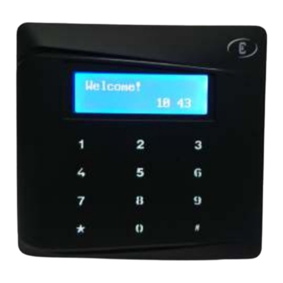
CHAPTER 1 EL374 Access Controller Introduction EL374 is Microprocessor controlled equipment that combines access controller, card reader and keypad in single unit. It is equipped with a 122 X 32 pixels backlit graphical LCD and a 12-key touch sense keypad. -
Page 5: Configuration
EL374 Access Control Panel Technical Manual Configuration The drawings below show the basic set-up of an EL374 system. There are 4 configurations available. Stand alone, normal mode Stand alone, secure mode PC linked, through RS485 of Local Area Network (LAN) In the standalone mode, all programming is carried out using built-in keypad. - Page 6 The first configuration has low security, because the EM lock is connected directly to EL374 and can be tampered with, as EL374 is installed in a non-secure area. For better security, EL374 should be fitted with an EL5Z remote relay unit mounted in a secure zone as shown in the second diagram.
-
Page 7: Principle Of Operation
‘yes’, and the EL374 is configured as card only mode, it will activate the electric lock to unlock the door. If the EL374 is configured as card + pin mode, then it will wait for the PIN (Personal Identification Number) to be keyed in. If any of the above 3 tests fail, the door will not be unlocked. -
Page 8: Normal Operation
ID number to be read. For example, you can specify that EL374 reads 40 bits of the card output, and select bits 20 to 40 as the ID number. In this case, the first 20 bits will be ignored, and only bits 20 to 40 are read. -
Page 9: Timer And Time Zone
Timer and Time Zone A powerful feature provided by EL374 is the ability to grant or deny access depending on time. This is done by setting “Timers” and “Access Time Zone”. A timer has 2 sets of “start” and “end”... -
Page 10: Logging Of Activities
(time zones 1 & 2 are pre-defined). Logging of Activities The EL374 is able to log up to 2000 records of the latest activities (or transactions) occurring at the door it is controlling. Each record is stored with date, time, card ID and transaction code. - Page 11 EL374 Access Control Panel Technical Manual CODE Meaning of Code Valid Entry Invalid Entry Invalid PIN Door Open Alarm Invalid Customer Code Invalid Time Zone Valid Entry (out reader)r Sensor Alarm Sensor Arming Output On Output Off...
-
Page 12: Chapter 2
EL5Z and EL374 to 12 feet. This 12 feet cable has 4-pin plugs at both ends. One plug is to be inserted at the bottom right hand corner of EL374 (CN3), and the other is to be inserted in the top left hand corner of EL5Z (marked as CN3 on EL5Zv2, or CN1 on EZ5/EL5Zv1). -
Page 13: Input /Output Points Installation
If you do not use EL5Z, then just pull a 2-core cable between the 12V supply and EL374. The Door Sensor (magnetic contact), the Exit Push Button and the Electric Door Lock are connected to CN5 of EL374. - Page 14 If you want EL374 display in Chinese, you should press down key <4> on the keypad and switch the Power Supply ON. However, you can also change the language any time by programming.
- Page 15 Yes : Using pre-set PIN which is obtained by a simple propriety encryption algorithm and the PIN value is shown as PIN2 on cards supplied by Elid. If you are an authorized distributor of Elid, you can obtain the PIN generation program from Elid.
-
Page 16: Chapter 3
PROGRAMMING MODE The Operation of Keypad EL374 is equipped with a 12-button touch keypad and a LCD display. The keypad functions are as follows:- There are 12 keys on the keypad. These keys can be divided into the following categories:- Special function keys <2>, <5>, <*>... -
Page 17: Commands
EL374 Access Control Panel Technical Manual Commands There are 4 main menus in EL374:- Time Menu Card Menu Set-up Menu Self-test Menu Under Time menu, there are 5 commands as follows:- Date / Time Set date and time of the internal clock. - Page 18 Note that the unit will only respond to the Master Card after it has been properly initialized by the “Powering Up Procedure” described in Section 2.4 above. Note also that if you press the <*> key, EL374 will go back to the normal operation mode where the display will show the time in hours and minutes.
-
Page 19: Chapter 4
TIME MENU Set Date / Time This command allows you to set internal calendar clock of EL374. The calendar clock must be set to the correct date, time and day of week before the time related operation can function correctly. The display will show:... -
Page 20: Set Timer
EL374 Access Control Panel Technical Manual Tuesday Wednesday Thursday Friday Saturday When this field is set and the <#> key is pressed, the set DATE/TIME command is complete and the display jumps back to: 1 Time Menu Date/Time Set Timer The timers define the time restriction to be used in the Access Time Zone, Automatic Lock Release Time Zone, and Automatic PIN Mode Disable Time Zone for each day of the week. - Page 21 EL374 Access Control Panel Technical Manual The following display will show: Set Timer S1: 00 Enter in the start hour <0 8> followed by the <#> key. The display will now proceed to the minute field S2 as follows: Set Timer S2: 00 Enter in the minute value of the start time.
-
Page 22: 4.3 Set Holiday
Wednesday, and is declared as a holiday, then when Dec 25 arrives, EL374 will not use Wednesday for processing the time zones and time categories, it will use the Holiday timer settings. EL374 caters for a total of 20 holidays. When enter into this command, the display will show: Set Holidays 01: 00 The first 2 digits show the holiday number, in this case, holiday ‘# 1’. - Page 23 EL374 Access Control Panel Technical Manual You should consider your staff structure and working hours and then draw up a table such as the one shown in Section 1.6, which is reproduced below:- Timer For Time Zone Predefined as ‘No Entry’ at all times Predefined as entry permitted at al times Note that time zone 2 is a pre-programmed time zone which offers FREE ACCESS.
-
Page 24: Set Miscellaneous Time Zone
EL374 Access Control Panel Technical Manual You can now proceed to set Time Zone 4 Timers. Repeat until you have set all the time zones you need. Note that you can abort the operation at any time by pressing the <ESC> or <*> key. - Page 25 Monday……Holiday just as before. As explained above, this allows you to automatically change the setting of EL374 to operate in Card + PIN mode (timers=off) or Card mode (timer=on). In a former case, the user has to wave the card, then key in a 4 digit PIN code. In latter case, he only needs to wave his card.
-
Page 26: Chapter 5
EL374 Access Control Panel Technical Manual CHAPTER 5 CARD MENU Add Card Via Reader This command allow you to add card by just ‘wave’ the card at the reader, and that card will be read and installed. 2 Card Menu Add w Card Once press <#>, the display is as follows:... -
Page 27: Add Card Via Keypad
EL374 Access Control Panel Technical Manual And after that, you will be taken back to the screen ADD by card INST To escape, press <*> Add Card Via Keypad When this command is activated, cards may be added into the card holder database by keying in the card number. -
Page 28: Remove Card Via Reader
123456 to 123467, that is, 12 consecutive cards, all of time zone 2, just key in <1 2> followed by <#>. EL374 can store up to 2000 cards. When the memory is full, the display will give the message “FULL”. -
Page 29: Remove Card Via Keypad
EL374 Access Control Panel Technical Manual Remove Card Via Keypad This command removes existing cards from the card holder database by using keypad. 2 Card Menu Del w Keypad On activating this command, the following screen appears: DEL by Keypad... - Page 30 EL374 Access Control Panel Technical Manual On activating this command, the following display will appear: 2 Card Menu Set Code Below is an example of entering Code set #1 with a value of 3456 under Time Zone 2. Code Entry PN: _ Enter any PIN code between 1 and 3, in this case, press <1#>.
-
Page 31: Chapter 6
Set-up MENU Set Unit Number & Baud Rate This command allows you to set the unit address of the EL374 and baud rate of the serial communication port. Up to 16 units of EL374 can be wired to the same communication bus. The PC which links these units must be able to specify which unit it wishes to communicate with. -
Page 32: Set Door Parameter
EL374 Access Control Panel Technical Manual key in <3> followed by <#>. Set Door Parameter This command allows 3 parameters to be set. These are:- Permanent Lock Release Enable/Disable PIN Mode Enable/Disable No Entry Mode Enable/Disable Permanent Lock Release, when enabled will cause the lock to be activated all the time, meaning that the door is permanently unlocked, until the command is reversed. -
Page 33: Set Door Contact Type & Lock Release Time
This is to set built-in buzzer as alert when door is left open. Default is OFF. To turn this function on, key in <1#>. Set Auxiliary Output EL374 is equipped with an auxiliary output point which can be programmed for 4 modes of... -
Page 34: Set El5Z Id Code And Customer Code
Each EL5Z unit comes with a unique ID 6-digit address code. This number is on a slip of paper pasted to the casing of EL5Z. The EL374 controller must know the ID code of the EL5Z connected to it; otherwise, communication cannot be established. - Page 35 EL374 Access Control Panel Technical Manual numbers display. 3 Setup & Util EL5Z & CC Press <#> and the display as follows will appear: EL5Z NN_NN_NN M1: 00 First two digits of the EL5Z code Key in the first 2-digit of EL5Z code. For example, the EL5Z code is “031120”, then you should key in <03#>.
-
Page 36: Power Save
Print Transaction Report and Card Database This command allows you to print a report of all transactions stored in the EL374 buffer. Before you execute this command, you must connect the RS485 output to a PC. The PC should run a terminal program such as HyperTerminal or Bray. -
Page 37: Backup & Restore
Note that data in backup area will not be erased by a cold-start. Therefore, it is always a good idea to back-up settings of EL374. When something is wrong with the controller and you need to restart everything, you can take the following steps:-... - Page 38 EL374 Access Control Panel Technical Manual appear: Engl / Chinese CHIN Press key <#> to confirm the setting.
-
Page 39: Chapter 7
EL374 Access Control Panel Technical Manual CHAPTER 7 SELF-TEST COMMAND This section explains self tests available in the EL374 unit for diagnostic purposes. On entering self-test command, the display will show: 4 Self-Test Input T You can now select different diagnostic tests as listed in the table below by using <2> or <5>... -
Page 40: Output Test
Now type any number on the PC terminal, and the character will be echoed on LCD screen on EL374. Similarly, if you press any key on EL374, that key will be echoed on the PC screen. Press <*> key to escape. -
Page 41: Keypad Test
4 Self-Test Reader T Now present a proximity card to the reader that connected to EL374, and the display will show the card ID number. For example, if the card has the number 051687, the screen will show Reader Test 051687 Press <*>... -
Page 42: Hard Reset
Key in 123456 and follow the cold start procedures described in 2.4. If your intention is to do flash programming to update EL374 firmware, you do not have to do anything after pressing <#>. The procedures are described in a separate document entitled “How to upgrade firmware in EL360 and EL374”...
Need help?
Do you have a question about the EL374 and is the answer not in the manual?
Questions and answers