Table of Contents
Advertisement
Quick Links
Advertisement
Table of Contents

Summary of Contents for FIRETRACE 800095-A
- Page 1 INSTALLATION MANUAL DUAL PRESSURE SWITCH MODULE WITH & WITHOUT BYPASS DIOM P/N: 800095-A Firetrace USA LLC Firetrace International LLC North and South America 8435 N. 90 St, Suite 2 Scottsdale, AZ 85258 USA Telephone: 480-607-1218 Fax: 480-315-1316 www.firetrace.com...
- Page 2 DESCRIPTION OF CHANGE APPRVD. DATE INITIAL RELEASE DCR22-012 7/22/2022 Dual Pressure Switch Module – Installation Manual Originally Prepared By: Zach Smith DIOM 800095-A 7/22/2022...
-
Page 3: Table Of Contents
Figure 13 – Flanges Installed ......................................10 Figure 14 – Magnetic Mounting Kit ....................................10 Figure 15 – Magnets Installed ......................................10 Figure 16 – Cable Harness Install | Exploded View ................................11 Figure 17 – Harness Pinout Diagram ....................................11 DIOM 800095-A 7/22/2022... - Page 4 Table 2 – Configuration Specification | With Bypass ................................6 Table 3 – Configuration Specification | Standard ................................6 Table 4 – Testing Reference | With Bypass ..................................7 Table 5 – Testing Reference | Standard ..................................... 8 Table 6 – Pinout Details........................................11 DIOM 800095-A 7/22/2022...
-
Page 5: Foreword
Safety precautions are essential when any electrical or mechanical equipment is involved. These precautions should be followed when handling, servicing, and recharging Firetrace Fire Suppression Systems and equipment. If safety precautions are overlooked or ignored, personal injury or property damage may occur. -
Page 6: General
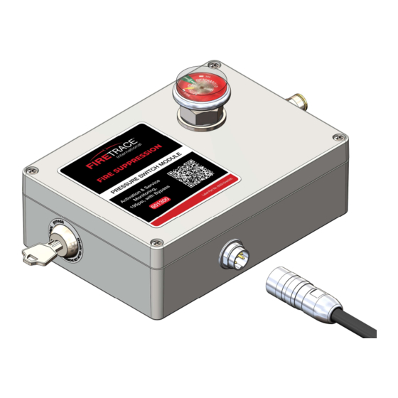
2.1 Description The Dual Pressure Switch Module gives the ability to monitor the health of the Firetrace fire suppression system and deliver a shutdown / notification signal in the event of a system discharge due to fire in a single package solution. The pressure switch module also contains an integrated end-of-line adapter to help simplify the installation process. -
Page 7: Standard (Without Bypass)
The electrical limitations below are for both variants of the Dual Pressure Switch Module, with and without bypass key switch. Max Voltage: 24V Max Current: 2A 2.4.2 Environmental Variant Operating Temp -40°F to 150°F With Bypass -40°C to 65.6°C -40°F to 150°F Standard IP64 -40°C to 65.6°C Figure 5 – Environmental Limitations DIOM 800095-A 7/22/2022... -
Page 8: Installation
Pressurize the Firetrace detection tubing. The rest of the installation of the Firetrace fire suppression systems should follow the instructions called out in the specific DIOM of the system being installed. Reference the following sections for more detail on each of the steps outlined above. -
Page 9: Configuring The Module
Table 2 & Table 3. The identification numbers for the toggle switches are screen-printed onto the PCB The bypass key switch can be configured to perform distinct functions on each of the pressure switches when the key is moved to the bypass position. Figure 8 – Configuration Board Overview DIOM 800095-A 7/22/2022... -
Page 10: Configuration Testing
Table 3 – Configuration Specification | Standard Install Module PS1* PS2* Requirements Config # No Bypass * Pressure switch configured to either normally open (NO) or normally closed (NC). Reference Table 1 for pressure switch details 3.3 Configuration Testing DIOM 800095-A 7/22/2022... -
Page 11: Table 4 - Testing Reference | With Bypass
Open Closed Normal Open Open Closed Closed Bypass Closed Open Closed Closed Normal Open Closed Closed Open Bypass Closed Closed Closed Open Normal Closed Closed Open Open Bypass Closed Closed Open Open Normal Closed Open Open Closed DIOM 800095-A 7/22/2022... -
Page 12: Closing The Module
Thread locker should be used in higher vibration environments. If mounted in a vertical orientation, remove the nameplate from the module and apply the supplied nameplate so that the content is readable. Figure 10 – Threaded Insert DIOM 800095-A 7/22/2022... -
Page 13: Direct Mounting
Figure 12 below highlights what is provided in the Flange Mounting Kit (P/N 111152). Figure 13 below shows the flanges installed on the module. Figure 12 – Flange Mounting Kit DIOM 800095-A 7/22/2022... -
Page 14: Wiring The Module
Tighten to finger tight. Figure 17 below details the pin locations on the harness. Table 6 indicates the relationship between each pin and wire and the pressure switch associated with them. Cable shielding can be utilized by connecting directly to the shielding in the cable, if needed. DIOM 800095-A 7/22/2022... -
Page 15: System Activation
Install the detection tubing throughout the enclosure. Ensure all necessary fittings and accessories are installed in accordance with the procedures specified in the DIOM of the Firetrace suppression unit being installed With the unit ball valve in the closed position, thread the tube fitting into the ball valve attached to the top of the cylinder valve. -
Page 16: Service And Maintenance
4.2 Post Discharge, System Recharge, and Return to Service An authorized Firetrace distributor must be consulted after a system has discharged. The units must be removed and recharged. To remove the connected Firetrace Suppression unit(s) please refer to that unit’s manual to return to service. - Page 17 5 APPENDIX A Direct Mounting Hole Location Print Out DIOM 800095-A 7/22/2022...
- Page 18 DIOM 800095-A 7/22/2022...
Need help?
Do you have a question about the 800095-A and is the answer not in the manual?
Questions and answers