Table of Contents
Advertisement
Quick Links
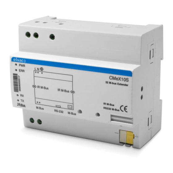
CMeX10S-13S
DIN-mounted M-Bus master for 32-256 M-Bus unit loads
INTRODUCTION
The CMeX10S/11S/12S/13S is an M-Bus master for up to 256 M-Bus unit
loads. For a complete description of the product or for information in
Swedish, visit the Elvaco AB website, www.elvaco.com.
OVERVIEW
MOUNTING
The product should be mounted on a DIN-rail. The DIN-lock (4) on the
bottom is used to mount and demount the unit from the DIN-rail. To
fully comply with safety regulations, a DIN-rail enclosure must cover the
terminals and a disconnector switch on power supply must be used.
M-BUS 2-WIRE BUS
M-Bus is a multi-drop 2-wire bus with no polarity. Use a cable of area
0.25-1.5 mm
, e.g. a standard telephone cable (EKKX 2x2x0.5). Connect
2
the wiring to the connector (1, 2) or the push wire connector (6). Do not
exceed the maximum cable length of 5000 m.
IMPORTANT
•
CMeX10S/11S/12S/13S handles from 32 up to 256 unit loads. Be
sure to use the correct model in your application. Overloading the
bus will turn on the ERR LED and turn off the M-Bus bus.
•
All connected M-Bus unit loads must have unique primary or
secondary M-Bus addresses depending on addressing mode.
1.
M-Bus out
2.
M-Bus out
3.
RS232 in
4.
DIN-rail lock
5.
IR interface
6.
M-Bus out
7.
Protective earth
8.
Power supply N
9.
Power supply L
10. Power LED (green)
11.
Error LED (red)
12.
Serial number
13.
RX LED (yellow)
14.
TX LED (yellow)
IR INTERFACE
The IR interface can be used beside an ABB electricity meter or
another CMeX module. Remove the IR shield (5) and mount the
CMeX10S/11S/12S/13S on the left side of the meter or CMeX module and
leave no space between the products. Do not remove the shield unless
the IR interface is used.
RS232 INTERFACE
Use the RS232 interface to use the CMeX10S/11S/12S/13S as an M-Bus
master from RS232 to M-Bus 2-wire interface.
POWER SUPPLY
The installation should be performed by a qualified electrician or an
installer with the required knowledge. If the product is mounted in an
overvoltage category 3 (OVC III) environment, an external transient
protection must be installed before the CMeX10S-13S. The power supply
should be connected via a switch so the unit can be switched off during
service work. The main supply should be connected to screw terminal
(8) and screw terminal (9). Main supply voltage should be in the range of
100-240 VAC, 50/60 Hz, fused with 10A. Connect ground
to screw terminal (7).
LED INDICATIONS
Green PWR LED
PWR LED indicates mains supply.
Mode
Description
Permanently on
Mains power connected
Permanently off
No mains power
connected
Red ERR LED
ERR LED indicates M-Bus 2-wire bus status.
Mode
Description
Permanently on
Short circuit of the M-Bus
2-wire bus
Permanently off
Normal mode, idle
Short flash every
No M-Bus unit loads
second
connected
Flashing for 1
M-Bus unit load collision
second
Yellow RX LED
RX LED indicates communication from M-Bus unit loads to DTE.
Mode
Description
On/Flashing
M-Bus unit load is
transmitting data
Off
M-Bus unit load is not
transmitting data
Visual
Visual
Visual
Advertisement
Table of Contents

Related Manuals for Elvaco CMeX10S


Summary of Contents for Elvaco CMeX10S
- Page 1 INTRODUCTION The IR interface can be used beside an ABB electricity meter or The CMeX10S/11S/12S/13S is an M-Bus master for up to 256 M-Bus unit another CMeX module. Remove the IR shield (5) and mount the loads. For a complete description of the product or for information in CMeX10S/11S/12S/13S on the left side of the meter or CMeX module and Swedish, visit the Elvaco AB website, www.elvaco.com.
- Page 2 © 2022, Elvaco AB. All rights reserved. The documentation and product are provided on an “as is” basis only and may contain deficiencies or in- CMeX10S-13S Quick manual A4 English adequacies.
Need help?
Do you have a question about the CMeX10S and is the answer not in the manual?
Questions and answers