
Related Manuals for Paul BUS

Summary of Contents for Paul BUS
- Page 1 BUS thermostat BUS thermostat Status: 06.11 Paul Wärmerückgewinnung GmbH August-Horch-Straße 7 08141 Reinsdorf Germany Tel.: +49(0)375 - 303505 - 0 Fax: +49(0)375 - 303505 - 55...
-
Page 3: Table Of Contents
Electric heater battery ......................7 3.2.2 Water supply heater ......................... 8 Ground pipe diverter (Valve for ground heat exchanger - ground pipe diverter valve) ....9 Appendices: Appendix 1: Wiring diagram BUS thermostat Appendix 2: Technical data BUS thermostat... -
Page 4: Introduction
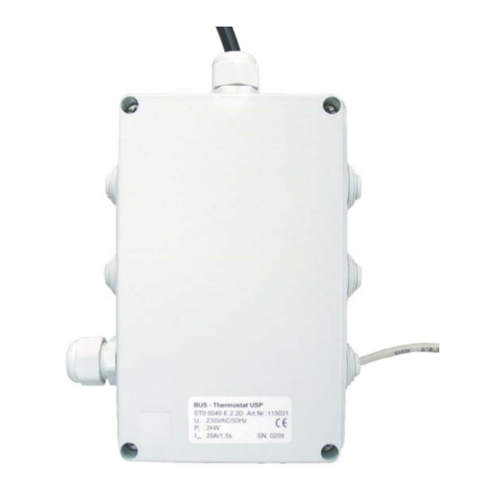
2 Installation The BUS thermostat shall be installed max. 2 m away from the device it controls. The housing is surface- mounted using 4 screws. A 230 VAC power supply has to be provided next to the BUS thermostat. The BUS thermostat has protection class IP 20. - Page 5 The RJ45 plug-in connection of the BUS thermostat, the adapter board and the Y- bord are for communication purposes with the internal RS485 BUS only! Every other use results in damaging the internal modules! All electrical connections of the BUS thermostat board are described in appendix 1 wiring diagram BUS thermostat.
-
Page 6: Operating Modes
S2.1 and S.2.2 of the DIP switch S2 defines the possible functions of the modules controlled by the BUS thermostat. The basic operating mode on the bus has to be unique. Using the BUS thermostat as control unit of the universal control realizes the following functions:... -
Page 7: Frost Protection Operating Mode
Figure 3: Functions of switch settings S2.1 and S2.2 of the DIP switch S2 3.1 Frost protection operating mode 3.1.1 Electric frost protection heater The electric frost protection heater has to be integrated in the intake air duct of the ventilation unit. The temperature sensor NTC has to be installed in the intake air duct downstream the electric frost protection heater and upstream the intake air connection of the ventilation unit. -
Page 8: Electric Frost Protection Heater With Resistance Heating Element
Figure 4: Configuration of electric frost protection heater with PTC heating element 3.1.1.2 Electric frost protection heater with resistance heating element The electric frost protection heater with resistance heating element has to be run with a digital flow indicator STR. The digital flow indicator is either part of the module or has to be installed separately in the intake air duct with a straight flow distance of 5 x DN. -
Page 9: Brine-Defroster
Figure 5: Configuration of electric frost protection heater with resistance heating element 3.1.2 Brine-defroster The brine-defroster has to be integrated in the intake air duct of the ventilation unit. The temperature sensor NTC has to be installed in the intake air duct upstream the brine-defroster. A brine-pump is actuated if a brine-defroster is used. -
Page 10: Water Supply Heater
The electric heater battery with resistance heating element has to be run with a digital flow indicator STR. The digital flow indicator is either part of the module or has to be installed separately in the supply air duct with a straight flow distance of 5 x DN. The combination of switch settings of the DIP switch S2, the terminal configuration X1 and X2 for control of the electric heater battery is shown in figure 7. -
Page 11: Ground Pipe Diverter (Valve For Ground Heat Exchanger - Ground Pipe Diverter Valve)
The temperature sensor NTC is an outdoor air temperature sensor, installed at a sun-protected place. The switch of both position is depending on if mains voltage on L1 is output or not. The BUS thermostat is able to control motors like "Belima LMC230 -F-CS". - Page 12 Figure 9: Ground pipe diverter valve configuration As of June 6th 2011...
- Page 14 The BUS thermostat is equipped with a pulse packet controlled or direct power output. The central communication control / monitoring including the 24 VDC power supply of the controller is realized via the RS485 BUS. The operating mode for the respective modules is configured using the DIP switch S2. The parameterization of the control functions for the above applications can be made only with the control panel TFT-Touch panel.
Need help?
Do you have a question about the BUS and is the answer not in the manual?
Questions and answers