Table of Contents
Advertisement
Quick Links
Puritan-Bennett Corp.
2800 Airwest Blvd.
Plainfield, IN 46168
Customer Service:
1-800-635-5267, press 2
Technical Support:
1-800-255-6774, press 2
Part Number B-701693-00 Rev. C (10/02)
©
2002 Puritan-Bennett Corp.
T
ECHNICAL
HELiOS™ Liquid Oxygen Reservoirs
(Standard and Universal)
HELiOS™ Liquid Oxygen Portables
CAUTION: Federal (U.S.A.) laws restricts this
!
device to sale by or on the order of a
physician.
M
ANUAL
Advertisement
Table of Contents
Troubleshooting

Subscribe to Our Youtube Channel
Related Manuals for Puritan Bennett Tyco HELIOS Reservoir


Summary of Contents for Puritan Bennett Tyco HELIOS Reservoir
- Page 1 Puritan-Bennett Corp. 2800 Airwest Blvd. Plainfield, IN 46168 Customer Service: 1-800-635-5267, press 2 Technical Support: 1-800-255-6774, press 2 ECHNICAL ANUAL HELiOS™ Liquid Oxygen Reservoirs (Standard and Universal) HELiOS™ Liquid Oxygen Portables CAUTION: Federal (U.S.A.) laws restricts this device to sale by or on the order of a Part Number B-701693-00 Rev.
- Page 2 LIST OF EFFECTIVE PAGES This list of effective pages represents manual P/N B-701693-00, Revision C. Revision Description Date Initial Release 05-00 Page Information Changes 10-01 Universal Res. & Parts Illus. Changes 10-02 Effective Pages Revision Effective Pages Revision Title Page 11-1 11-2, 11-3 12-1, 12-2...
- Page 3 DEFINITION OF STATEMENTS Statements in this manual preceded by the following words are of special significance: WARNING A warning describes conditions that concern your personal safety and the safety of others. It includes the actions required to prevent injury. Ignoring warnings can lead to injury or death. CAUTION: A caution informs you about conditions that may cause possible damage to the equipment or other property, or situations that may cause reduced or no oxygen flow.
- Page 4 PREFACE This manual provides the information needed to service the Puritan Bennett HELiOS Standard Reservoir, Universal Reservoir, and H300 Portable units. Information in the first section of this manual covers both the Reservoir and the Portable units. Information in Sections 2 through 7 covers just the Reservoir unit. Information in Sections 8 through 13 covers just the HELiOS 300 Portable unit.
-
Page 5: Table Of Contents
TABLE OF CONTENTS Section 1 –Introduction to the HELiOS System 1.1 HELiOS System Description ................1-1 1.2 Serial Number Identification ................1-3 1.3 Safety Precautions ................... 1-4 1.3.1 Cold Safety ....................1-4 1.3.2 Expansion Safety ..................1-5 1.3.3 Fire Safety ....................1-5 1.4 Liquid Oxygen Saturation Principles .............. - Page 6 3 – Reservoir Theory of Operation 3.1 Reservoir Components ..................3-1 3.1.1Cryogenic Container ................. 3-1 3.1.2 Fill Connector/Quick Connect ..............3-2 3.1.3 Vent Valve ....................3-3 3.1.4 Relief/Economizer Valve ................3-3 3.1.5 Secondary Relief Valve ................3-5 3.1.6 Pressure Regulator (Standard Reservoir Only) ........3-5 3.1.7 Warming Coil ...................
- Page 7 6.3.1 Removal ....................6-5 6.3.2 Service ..................... 6-6 6.3.3 Installation ....................6-6 6.4 Pressure Indicator (Standard Reservoir Only) ..........6-7 6.4.1 Removal ....................6-7 6.4.2 Service ..................... 6-7 6.4.3 Installation ....................6-7 6.5 Fill Connector Release Assembly ..............6-8 6.5.1 Removal ....................6-8 6.5.2 Installation ....................
- Page 8 7 – Reservoir Illustrated Parts List Figure 7-1, HELiOS Standard Reservoir ............7-3 Figure 7-2, HELiOS Standard Reservoir ............7-4 Figure 7-3, HELiOS Standard Reservoir ............7-5 Figure 7-4, HELiOS Universal Reservoir ............7-6 Figure 7-5, HELiOS Universal Reservoir ............7-7 Figure 7-6, HELiOS Universal Reservoir ............
- Page 9 10 – HELiOS 300 Performance Verification 10.1 Equipment Required ..................10-1 10.2 Leak Tests ......................10-2 10.2.1 Liquid Leak Detector Test ..............10-2 10.2.2 Pressure Hold Test (Alternate Leak Test) ..........10-4 10.3 Gaseous Oxygen Functional Tests ..............10-4 10.3.1 Primary Relief Valve Test ................ 10-4 10.3.2 Secondary Relief Valve Test ..............
- Page 10 12.7 Secondary Relief Valve ................. 12-19 12.7.1 Removal ....................12-19 12.7.2 Installation ..................12-19 12.8 Demand Flow Control Valve ................. 12-19 12.8.1 Removal ....................12-19 12.8.2 Service ....................12-20 12.8.3 Installation ..................12-20 12.8.4 Sensitivity Adjustment ..............12-20 12.9 Warming Coils ....................12-22 12.9.1 Removal –...
-
Page 11: Section 1 -Introduction To The Helios System
Standard Reservoir plus it permits filling the H300 Portable as well as the Puritan Bennett Companion 1000, Companion T, and Companion 500 series por- tables. The HELiOS 300 Portable unit sets a new standard for size, weight, and range that surpasses existing cylinder or liquid based portables. - Page 12 HELiOS Liquid Oxygen System Technical Manual Like today’s liquid oxygen systems, the HELiOS system consists of a Reservoir and a Portable patient unit (Figure 1-1). However, the system components are capable of working together rather than separately. The HELiOS 300 Portable fills from the Reservoir for ambulatory use or connects to the Reservoir with a flexible oxygen supply tube for home use.
-
Page 13: Serial Number Identification
HELiOS Liquid Oxygen System Technical Manual Bennett Companion portables as well. At the push of a button, an electronic contents indicator measures and displays the amount of liquid oxygen remaining in the Reservoir. The H-36 Reservoir, when used with an H-300 Portable, typically yields a four week liquid oxygen delivery cycle with a 2 L/min patient. -
Page 14: Safety Precautions
HELiOS Liquid Oxygen System Technical Manual SAFETY PRECAUTIONS This section covers precautions and safe practices as they apply to facilities and person- nel involved in servicing medical oxygen equipment. These precautions are divided into three main areas: cold safety, expansion safety, and fire safety. To ensure reliability and safety, the service techniques, work area, and equipment used in the storage, service, and handling of this system must be of the highest standard. -
Page 15: Expansion Safety
HELiOS Liquid Oxygen System Technical Manual Important Facts: • Direct exposure to liquid oxygen or exposure to its vented gas or components cooled by liquid oxygen can result in frostbite. If frostbite occurs, seek medical attention immediately. 1.3.2 Expansion Safety WARNING Explosive hazard. - Page 16 HELiOS Liquid Oxygen System Technical Manual WARNING Concentrated Oxygen. Increased risk of fire. • Keep oxygen equipment away from electrical appliances. Keep Reservoir and Portable units at least five feet from electrical appliances that may cause heat or sparks. • Keep oxygen equipment in a well-ventilated area at all times. These units periodically release small amounts of oxygen gas that must be ventilated to prevent buildup.
-
Page 17: Liquid Oxygen Saturation Principles
HELiOS Liquid Oxygen System Technical Manual LIQUID OXYGEN SATURATION PRINCIPLES Oxygen, in its normal state, is a colorless, tasteless, and odorless gas that is non-flam- mable, although it greatly accelerates combustion in high concentrations. It constitutes about 21% of the Earth’s atmosphere by volume. Oxygen in higher concentrations is medically beneficial to patients suffering from certain respiratory diseases. - Page 18 HELiOS Liquid Oxygen System Technical Manual Figure 1-8: Saturated (Boiling) Water at Higher Pressure If the pressure in a container of saturated liquid decreases, the temperature required for saturation to occur will decrease. This leaves the liquid “super saturated” or too warm. When this occurs, rapid boiling and vaporizing of some of the liquid occurs.
-
Page 19: Pressure Fittings And Connections
HELiOS Liquid Oxygen System Technical Manual Figure 1-10: Liquid Oxygen Saturation Curve It is important to maintain liquid oxygen saturation (boiling) at the specified operating pressure of the HELiOS system. As an oxygen flow demand is put on the system, a slight decrease in pressure occurs due to oxygen withdrawal. -
Page 20: Compression Fitting Remake
HELiOS Liquid Oxygen System Technical Manual Perform the following steps to make up a new compression fitting: Inspect the tube end. The tube end should be cut square and the outside surface of the tube should be free of scratches or other marks at least one inch (25 mm) back from the tube end. -
Page 21: Tapered Pipe Thread (Npt) Makeup
HELiOS Liquid Oxygen System Technical Manual If the leak detector forms bubbles at the front of the nut, between it and the fitting body, then the leak is probably between the ferrule and the fitting’s tapered seat. Check this area for imbedded dirt or cracks. -
Page 22: Tapered Pipe Thread Troubleshooting
HELiOS Liquid Oxygen System Technical Manual 1.5.5 Tapered Pipe Thread Troubleshooting Leaks at NPT fittings are usually the result of improper application of thread sealant or loosening of the fittings. To check for leaks, pressurize the system and use an oxygen- compatible leak detector (such as SNOOP) on the fitting threads. - Page 23 HELiOS Liquid Oxygen System Technical Manual TABLE 1-1. RECOMMENDED TOOLS, TEST EQUIPMENT & SERVICE MATERIALS TOOLS Hex Key (Allen) Wrench – 3/32 in., 7/64 in., 5/32 in. Local Source Open End Wrenches – ¼ in., ½ in., 9/16 in., 5/8 in., ¾...
- Page 24 HELiOS Liquid Oxygen System Technical Manual OPTIONAL (PORTABLE ONLY) Magnehelic Gauge Assembly – 0-25 in. H2O (Figure 1-20) Puritan-Bennett No. B-778208-00 Jet/Venturi Assembly (Figure 1-21) Puritan-Bennett No. B-778210-00 Jet/Venturi Puritan-Bennett No. B-778213-00 SERVICE MATERIALS Dual Lumen Cannula (Portable) Puritan-Bennett No. B-778057-00 (7 ft./2.1 m) Oxygen DISS Wye Outlet Adapter w/ Bay Corp., Westlake, OH-Part No.
- Page 25 HELiOS Liquid Oxygen System Technical Manual Portable Adapter P/N B-778203-00 Baseplate P/N B-778204-00 Figure 1-17: Portable Test Fixture B-778202-00 100 psig Pressure Gauge P/N B-776004-00 Disposable Tubing Barb Adaptor Tubing Barb Adaptor P/N B-776945-00 P/N B-775269-00 Small Tie Wrap P/N B-775091-00 Tubing - 3/16 in.
- Page 26 HELiOS Liquid Oxygen System Technical Manual Figure 1-19: Reservoir Pressurizing Fixture B-701731-00 Bracket P/N B-776594-00 High Pressure Port Low Pressure Port Figure 1-20: Magnehelic Gauge Assembly B-778208-00 1-16 - Introduction to the HELiOS System B-701693-00 Rev. B...
-
Page 27: Test Equipment Calibration
HELiOS Liquid Oxygen System Technical Manual Bleed Restrictor Port .024 in. (.61 mm) P/N B-778212-00 Bleed Port P/N B-778211-00 Jet/Venturi P/N B-778213-00 Tubing - 3/16 in. I.D. x 4 ft. Small- Tie Wrap (5 mm I.D. x 1.2 mm) P/N B-775091-00 P/N B-778214-00 Disposable Tubing Barb Adapter... -
Page 28: Accessories
HELiOS Liquid Oxygen System Technical Manual ACCESSORIES Accessories for the HELiOS Reservoir and Portable units are listed in Table 1-2. Table 1-2 HELiOS ACCESSORIES Description Part Number Location Van Companion Assembly (Delivery Cart) B-775462-00 Figure 1-22 • Strap and Buckle Assembly B-775477-00 Figure 1-22, #1 •... - Page 29 HELiOS Liquid Oxygen System Technical Manual Table 1-2 (cont.) HELiOS ACCESSORIES Description Part Number Location Shipping Carton, HELiOS 36 B-701690-00 Not Shown • Corner Post (4 Required) B-702011-00 Not Shown Shipping Carton, HELiOS 46 B-701691-00 Not Shown • Corner Post (4 Required) B-702011-00 Not Shown Shipping Carton, HELiOS 300 Portable...
- Page 30 HELiOS Liquid Oxygen System Technical Manual Figure 1-22: Van Companion Delivery Cart Figure 1-23: Roller Base 1-20 - Introduction to the HELiOS System B-701693-00 Rev. A...
- Page 31 HELiOS Liquid Oxygen System Technical Manual Figure 1-24: Transfer Line Assembly NOTE: Install the universal adapter kit on the transfer line assembly to allow the filling of both Puritan-Bennett and liquid oxygen units with side-fill connectors with the same transfer line. (Installs between the side-fill adapter and the transfer hose.) Figure 1-25: Universal Adapter Kit B-701693-00 Rev.
- Page 32 HELiOS Liquid Oxygen System Technical Manual Figure 1-26: Dual Lumen Cannula Figure 1-27: Oxygen Supply Tube Figure 1-28: Reservoir Fill Connector Cover 1-22 - Introduction to the HELiOS System B-701693-00 Rev. A...
-
Page 33: Section 2 - Reservoir General Information
The H-36 holds 36 liters (85 lbs/38.6 kg) of liquid oxygen while the H-46 holds 46 liters (110 lbs/49.9 kg) of liquid oxygen. The Reservoir uses the popular Puritan Bennett top fill connector and is compatible with Puritan Bennett Companion filling equipment (vent wrench, transfer hose assembly, source tank). -
Page 34: Helios Universal Reservoir
The U-36 holds 36 liters (85 lbs/38.6 kg) of liquid oxygen while the U-46 holds 46 liters (110 lbs/49.9 kg) of liquid oxygen. The Reservoir uses the popular Puritan Bennett top fill connector and is compatible with Puritan Bennett Companion filling equipment (vent wrench, transfer hose assembly, source tank) and Companion portables. -
Page 35: Performance Specifications
HELiOS Liquid Oxygen System Technical Manual PERFORMANCE SPECIFICATIONS The HELiOS Reservoir performance specifications are listed below in Table 2-1. TABLE 2-1 e t i e t i e t i e t i e t i e t i e t i e t i F °... -
Page 36: Unpacking, Installation, Repacking
HELiOS Liquid Oxygen System Technical Manual UNPACKING, INSTALLATION, AND REPACKING Perform the following procedures when unpacking, installing or repacking a HELiOS Reservoir unit. 2.3.1 Unpacking Examine the shipping carton for damage. If the carton is damaged, or its contents are suspected of being damaged, photograph the damaged carton before the Reservoir is unpacked. -
Page 37: Repacking For Return
2.4.1 Fill Connector The Reservoir uses the top fill Puritan Bennett fill connector to transfer liquid oxygen to and from the unit. It is the male half of a cryogenic quick connect coupling system. A spring loaded poppet automatically opens when the connec- tor is engaged and automatically closes when the connector is disengaged. -
Page 38: Vent Valve
HELiOS Liquid Oxygen System Technical Manual 2.4.3 Vent Valve The vent valve is a quarter-turn ball valve that is accessible with a separate vent wrench through a hole in the Reservoir upper shroud. The filling technician opens the vent valve to vent the inner container during the Reservoir unit filling process. -
Page 39: Filling Instructions
HELiOS Liquid Oxygen System Technical Manual Pressure Indicator Vent Fill Release (Standard Reservoir) Valve Connector Button Contents Oxygen Moisture Indicator Outlet Container FIGURE 2-2: Controls, Indicators, and Connectors FILLING INSTRUCTIONS The Reservoir must be filled with liquid oxygen saturated at 24 psig (166 kPa) to ensure proper operation. - Page 40 HELiOS Liquid Oxygen System Technical Manual Reservoir vent valve and/or source tank liquid valve to maintain 24 psig (166 kPa) on the Reservoir pressure gauge (internal gauge on standard Reservoir; external gauge con- nected to oxygen outlet on Universal Reservoir). However, liquid oxygen saturated at 40- 50 psig (276-345 kPa) is at a higher temperature than liquid oxygen saturated at 24 psig (166 kPa) (see Figure 1-10, Liquid Oxygen Saturation Curve).
-
Page 41: Transfer Line
2.5.2 Transfer Line The standard Puritan Bennett transfer line assembly (Figure 2-4) is used to transfer liquid oxygen from the source tank to the Reservoir. The 5/8-in. flared connection on the transfer line source adapter connects to a mating fitting on the source tank liquid withdrawal valve. -
Page 42: Pre-Fill Inspection
HELiOS Liquid Oxygen System Technical Manual 2.5.3 Pre-Fill Inspection Perform the following procedure to visually inspect the Reservoir and determine its operational status before filling. Correct observed problems before proceeding to fill the Reservoir. Ask the patient (where applicable) if there are any questions or concerns regarding the equipment since your last visit. -
Page 43: Filling Procedure
HELiOS Liquid Oxygen System Technical Manual 2.5.4 Filling Procedure Perform the following procedure to fill a HELiOS Reservoir with liquid oxygen. WARNING Fire hazard. Liquid oxygen spilled on asphalt or any other combustible surface will increase the possibility of fire if an ignition source is present. - Page 44 HELiOS Liquid Oxygen System Technical Manual STANDARD RESERVOIR If the Reservoir contains some liquid oxygen, verify that the Reservoir internal pressure gauge reads 24-48 psig (166-331 kPa) (Figure 2-6). A pressure reading outside of this range may indicate a problem. DO NOT attach an external pressure gauge to the oxygen outlet DISS connector.
- Page 45 HELiOS Liquid Oxygen System Technical Manual 10. Close and reopen the vent valve on the Reservoir after 45 to 60 seconds have passed. This will minimize the possibility of the vent valve freezing in the open position. NOTE: As the level of liquid oxygen nears the top of the Reservoir inner container, the sound and appearance of vapors escaping through the vent valve will change.
-
Page 46: Post-Fill Inspection
HELiOS Liquid Oxygen System Technical Manual 2.5.5 Post-Fill Inspection Perform the following procedure to inspect the Reservoir and determine its operational status after filling it with liquid oxygen. Correct observed problems before placing the unit in service. Refer to Sections 4 and 6 as needed to correct problems. Verify that the Reservoir fill connector poppet is closed and not leaking. -
Page 47: Resaturating Liquid Oxygen
HELiOS Liquid Oxygen System Technical Manual 2.5.7 Resaturating Liquid Oxygen If the HELiOS Reservoir looses its saturation pressure and you correct the cause of this condition without emptying the liquid oxygen contents, saturation pressure can be restored by simply allowing the unit to stand in normal room conditions. The entire volume of liquid will usually regain proper saturation within several days. -
Page 48: Maintenance
HELiOS Liquid Oxygen System Technical Manual Place one of the tubes from the dual-lumen oxygen cannula on the H-300 Portable oxygen outlet connector (upper connector). Place the other cannula tube on the sensor connector (lower connector). Adjust the cannula on the face to receive oxygen comfortably. - Page 49 HELiOS Liquid Oxygen System Technical Manual TABLE 2-2 RESERVOIR MAINTENANCE GUIDE ITEM ACTION Cleaning • Remove the upper shroud and clean the interior and exterior with a mild detergent and water. Wipe dry with a towel. Use cotton swabs in tight places. Use Scotch- Brite pad lightly with detergent to remove scuff marks.
-
Page 50: Reservoir Theory Of Operation
HELiOS Liquid Oxygen System Technical Manual Section RESERVOIR THEORY OF OPERATION This section describes the theory of operation for the HELiOS Reservoir liquid oxygen system. Two HELiOS Reservoir models are available, the Standard Reservoir and the Universal Reservoir. Each model comes in two sizes, 36 liquid liters and 46 liquid liters. The H-36 and U-36 models hold 36 liters (85 lbs/38.6 kg) of liquid oxygen while the H-46 and U- 46 models hold 46 liters (110 lbs/49.9 kg) of liquid oxygen. -
Page 51: Fill Connector/Quick Connect
HELiOS Liquid Oxygen System Technical Manual Conduction is the transfer of heat through a material, such as metal, by collisions of molecules in the material. Molecules at the hotter end of the material are moving faster than molecules at the cooler end. Heat is transferred from molecule to molecule as fast moving molecules run into the slower moving ones. -
Page 52: Vent Valve
HELiOS Liquid Oxygen System Technical Manual Figure 3-2: Male Fill Connector Figure 3-3: Male/Female Fill Connectors Fully Engaged 3.1.3 Vent Valve The vent valve (Figure 3-4) is a quarter turn ball valve that vents the HELiOS Reservoir inner container to atmosphere. Venting of the inner container is required to fill the Reser- voir with liquid oxygen. - Page 53 HELiOS Liquid Oxygen System Technical Manual pressure until equilibrium is established between the opening and closing forces on the diaphragm. The rate at which gas is vented out the primary relief valve is determined by the normal evaporation rate (NER) of the system. The Standard Reservoir maintains a primary relief valve nominal pressure of 45 psig (311 kPa) when in the Standby condition.
-
Page 54: Secondary Relief Valve
HELiOS Liquid Oxygen System Technical Manual 3.1.5 Secondary Relief Valve The secondary relief valve in the HELiOS Reservoir is used as a safety backup in the event that the primary relief valve fails to limit system pressure to an acceptable range. It is mounted on the relief/economizer valve body. -
Page 55: Warming Coil
HELiOS Liquid Oxygen System Technical Manual FLOW NO FLOW Regulator Regulator Spring Spring Diaphragm/Pin Diaphragm/Pin Assy. Assy. Inlet Pressure Inlet Pressure Outlet Pressure Outlet Pressure ~ 27-45 PSIG 27-45 PSIG 22 PSIG 22 PSIG (152 kPa) (186-311 kPa) (186-311 kPa) (152 kPa) Poppet Assy. -
Page 56: Pressure Indicator (Standard Reservoir Only)
HELiOS Liquid Oxygen System Technical Manual Closed Open Figure 3-9: Oxygen Outlet w/Poppet Valve 3.1.9 Pressure Indicator (Standard Reservoir Only) The HELiOS Standard Reservoir pressure indicator (Figure 3-10) is a bourdon tube pressure gauge that indicates the status of the system headspace pressure. The indicator dial is calibrated from 0 to 100 psig (0 to 7 bar). -
Page 57: Reservoir Operation
HELiOS Liquid Oxygen System Technical Manual the relative level of liquid oxygen remaining in the Reservoir. In addition to the green LEDs, a yellow “low contents” LED on the contents indicator lights when 8.5 pounds (3.9 kg) of liquid oxygen remain. A yellow “low battery” LED lights when the battery voltage drops below a predetermined value. - Page 58 HELiOS Liquid Oxygen System Technical Manual Fill Connector Pressure Gauge (Standard Reservoir) Oxygen Outlet Contents Indicator Pressure Regulator (Standard Reservoir) Gas Sense Tube Warming Coil Liquid Sense Tube Secondary Relief Valve Relief*/Economizer** Valve Neck Tube Vent Valve Vacuum Plug Liquid Withdrawal Inner Container Tube Outer Container...
-
Page 59: Fill Termination
HELiOS Liquid Oxygen System Technical Manual 3.2.2 Fill Termination When the liquid oxygen level in the Reservoir inner container reaches the end of the neck tube, liquid oxygen travels up the neck tube and discharges through the open vent valve (Figure 3-13). -
Page 60: Standby
HELiOS Liquid Oxygen System Technical Manual 3.2.3 Standby When the Reservoir contains liquid oxygen, and there is no oxygen flow demand on the system, the pressure in the system increases and eventually stabilizes at the primary relief valve set point, approximately 45 psig / 311 kPa for the Standard Reservoir or 26 psig / 179 kPa for the Universal Reservoir (Figure 3-14). -
Page 61: Gaseous Oxygen Use
HELiOS Liquid Oxygen System Technical Manual 3.2.4 Gaseous Oxygen Use Oxygen that flows through the Reservoir oxygen outlet can come from two locations within the Reservoir: the headspace above the liquid oxygen and the liquid withdrawal tube. When the pressure inside the Reservoir unit is greater than the economizer set point, the economizer valve opens. - Page 62 HELiOS Liquid Oxygen System Technical Manual When headspace pressure reaches the economizer set point, the economizer valve spring force overcomes the opposing force created by the pressure acting on the valve dia- phragm and closes down the valve. However, the economizer valve stays open just enough to allow the small flow of headspace gas created by the NER to pass through.
-
Page 63: Helios Reservoir Operation Over 24 Hours
HELiOS Liquid Oxygen System Technical Manual 3.2.5 HELiOS Reservoir Operation Over 24 Hours When using the HELiOS system, a patient is typically always connected to the H-300 Portable. If patient ambulation is required, the patient fills the H-300 with liquid oxygen from the Reservoir. - Page 64 HELiOS Liquid Oxygen System Technical Manual Figure 3-18 shows the change in pressure in the Universal Reservoir as a patient uses the system over a typical 24-hour period. The operation is similar to the Standard Reservoir. However, when there is no gaseous oxygen flow from the Reservoir to the H300, the time it takes for the headspace pressure to build to the relief valve opening point is shorter.
-
Page 65: Reservoir Performance Verification
HELiOS Liquid Oxygen System Technical Manual Section RESERVOIR PERFORMANCE VERIFICATION This section provides testing information to verify Reservoir performance for any of the following reasons: • To determine the cause of operational failure. • To check the unit’s overall system operation after the repair or replacement of a component. -
Page 66: Leak Tests
HELiOS Liquid Oxygen System Technical Manual LEAK TESTS Liquid oxygen leakage from the Reservoir unit in any amount is unacceptable and calls for the immediate removal from service of any such leaking unit. Minor gas leaks in connec- tions and fittings will not affect system operation provided they do not exceed the Normal Evaporation Rate (NER) of the unit. - Page 67 HELiOS Liquid Oxygen System Technical Manual (a) Place coated strap end between (b) Route strap between pressure contents indicator and R/E valve regulator and container flange (c) Adjust strap to its longest length (d) Push fixture down and pull up and snap together connectors on loose end of strap to secure Figure 4-1: Securing Pressurizing Fixture to Reservoir...
- Page 68 HELiOS Liquid Oxygen System Technical Manual WARNING Extreme cold hazard. Rapid discharge of liquid oxygen and/or system malfunction can occur. Use only Snoop liquid leak detector on the Reservoir unit fill connector. When finished with leak test, rinse the fill connector with clean water and blow dry completely with gaseous oxygen or nitrogen.
-
Page 69: Pressure Hold Test (Alternate Leak Test)
HELiOS Liquid Oxygen System Technical Manual 4.2.2 Pressure Hold Test (Alternate Leak Test) NOTE: Conduct the Pressure Hold Test on Reservoirs with empty, warm inner containers only. Performing this test on units that contain liquid oxygen yields inaccurate results. If the Reservoir contains liquid oxygen, remove the liquid oxygen from the unit per Reservoir Service and Repair, Section 6.1. -
Page 70: Gaseous Oxygen Functional Tests
HELiOS Liquid Oxygen System Technical Manual GASEOUS OXYGEN FUNCTIONAL TESTS Conduct the following tests on an empty Reservoir unit that has warmed to room temperature. 4.3.1 Primary Relief Valve Test The primary relief valve maintains system pressure at a preset value when the Reservoir contains liquid oxygen and is in the standby mode. -
Page 71: Secondary Relief Valve Test
HELiOS Liquid Oxygen System Technical Manual 4.3.2 Secondary Relief Valve Test The secondary relief valve serves as a safety or backup to the primary relief valve. Under normal operating conditions, the secondary relief valve remains closed. The relief valve opens at a specified pressure greater than the opening pressure of the primary relief valve. This test uses only gaseous oxygen to determine if the secondary relief valve opens within its acceptable range. -
Page 72: Pressure Indicator Test (Standard Reservoir Only)
HELiOS Liquid Oxygen System Technical Manual 4.3.3 Pressure Indicator Test (Standard Reservoir Only) The Reservoir pressure indicator is a bourdon tube pressure gauge that indicates the status of the pressure in the system upstream of the pressure regulator. The pressure indicator does not indicate the pressure at the Reservoir oxygen outlet. -
Page 73: Flow Restrictor Test
HELiOS Liquid Oxygen System Technical Manual Set the 22 psig (152 kPa) external flow control valve to 0. Verify that the test pressure gauge connected to the wye outlet reads 20.5-23.5 psig (141-162 kPa). Set the 22 psig (152 kPa) external flow control valve to 4 L/min. Verify that the test pressure gauge connected to the wye outlet still reads 20.5-23.5 psig (141-162 kPa). - Page 74 HELiOS Liquid Oxygen System Technical Manual Use a length of 3/16-in. ID flexible tubing to connect a 0-40 L/min test flowmeter to a tubing barb adapter. Connect the flowmeter to the oxygen outlet (Figure 4-9). Standard Reservoir Shown Figure 4-9: Flow Restrictor Test Setup STANDARD RESERVOIR Slowly increase the pressure in the Reservoir to 40 psig (276 kPa).
- Page 75 HELiOS Liquid Oxygen System Technical Manual NOTE: If you plan on performing the Normal Evaporation Rate (NER) Test following this test, fill the Reservoir so that it contains 20 to 25 lbs (9 to 11 kg) of liquid oxygen saturated as close to primary relief valve pressure as possible. This may require you to partially close the Reservoir vent valve during the fill.
- Page 76 HELiOS Liquid Oxygen System Technical Manual NOTE: Some venting of gaseous oxygen through the relief valve is normal. Perform a leak test on the unit (Section 4.2) and verify that the results are acceptable. Fill the unit with 20 to 25 lbs (9 to 11 kg) of liquid oxygen saturated as close to primary relief valve pressure as possible.
- Page 77 HELiOS Liquid Oxygen System Technical Manual STANDARD RESERVOIR To begin the test, the pressurizing fixture gauge should read 34-36 psig (235-248 kPa). If the gauge reading is higher, open the Reservoir vent valve to reduce the pressure. If the gauge reading is lower, allow time for the satura- tion pressure to increase to 34-36 psig (235-248 kPa).
- Page 78 HELiOS Liquid Oxygen System Technical Manual Section RESERVOIR TROUBLESHOOTING Table 5-1 provides troubleshooting procedures for the HELiOS Reservoir. This guide is not all-inclusive but is intended to serve as a general outline for solving operational problems. The table describes symptoms, identifies probable causes, and suggests corrective actions.
- Page 79 HELiOS Liquid Oxygen System Technical Manual Table 5-1 (cont.) l t u e l l . ) ) l t u l t u . ) ) e l l i l e i l e i l e . y l .
- Page 80 HELiOS Liquid Oxygen System Technical Manual Table 5-1 (cont.) o l f l t u . t e l t u . t e a i t u r t i t c o l f o l f c i r .
- Page 81 HELiOS Liquid Oxygen System Technical Manual Section RESERVOIR SERVICE AND REPAIR This section provides procedures for servicing the individual components of the Reser- voir. Included are instructions, where applicable, for removal, disassembly, operational check, cleaning, inspection, adjustment, reassembly, and installation. WARNING Personal injury can occur from the uncontrolled release of pressur- ized gaseous and liquid oxygen.
- Page 82 HELiOS Liquid Oxygen System Technical Manual WARNING Explosive hazard. Extremely high pressure can rupture the transfer line. Make sure the specified pressure relief valve is present, in the proper location, and functioning properly. After use, position the transfer line relief valve so that any liquid oxygen trapped in the line discharges in a safe direction as the line warms.
- Page 83 HELiOS Liquid Oxygen System Technical Manual SHROUD ASSEMBLY The Reservoir unit’s shroud assembly includes an upper shroud and a lower shroud. Both components are molded from an impact resistant plastic and protect the plumbing compo- nents on top of the unit. 6.2.1 Upper Shroud Removal Remove the two pan head screw from the topside of the upper shroud.
- Page 84 HELiOS Liquid Oxygen System Technical Manual Use a ¾-in. open-end wrench to remove the vent valve from the threaded manifold extension tube. Place the wrench on the valve hex flats closest to the manifold extension tube to prevent disassembly of the valve. Use a 9/16-in.
- Page 85 HELiOS Liquid Oxygen System Technical Manual Position the mounting bracket with attached components over the manifold so that the release lever is over the R/E valve. Carefully insert the Teflon liquid withdrawal tube into the open end of the aluminum warming coil tube. Be careful not to kink or scrape the Teflon tube.
- Page 86 HELiOS Liquid Oxygen System Technical Manual Remove the flexible black (gas) pressure sense tube from the barbed fitting (“LO”) on the contents indicator. Remove the flexible red (liquid) pressure sense tube from the barbed fitting (“HI”) on the contents indicator. 6.3.2 Service The contents indicator is not field serviceable except for replacement of the 9-volt battery.
- Page 87 HELiOS Liquid Oxygen System Technical Manual Black (Gas) Red (Liquid) Sense Tube Sense Tube “LO” “HI” Figure 6-3: Contents Indicator Pressure Sense Tube Routing (Standard Reservoir Shown) PRESSURE INDICATOR (STANDARD RESERVOIR ONLY) The pressure indicator is a 0-100 psig (0-7 bar) bourdon tube pressure gauge that indicates the status of the pressure in the system upstream of the pressure regulator.
- Page 88 HELiOS Liquid Oxygen System Technical Manual FILL CONNECTOR RELEASE ASSEMBLY The fill connector release assembly disengages the female fill connector from the male fill connector upon completion of a fill. It consists of a release button and lever assembly. NOTE: The Standard Reservoir release lever is different than the Universal Reservoir release lever.
-
Page 89: Inspection
HELiOS Liquid Oxygen System Technical Manual 6.6.2 Inspection Inspect the Kel-F poppet on the cartridge assembly for wear, damage, or embedded contaminants. Inspect the fill connector body for wear or damage. Inspect the tapered sealing surface for embedded debris or scratches. 6.6.3 Service Service to the male fill connector consists of replacing the fill connector assembly or... -
Page 90: Reassembly
HELiOS Liquid Oxygen System Technical Manual 6.6.5 Reassembly Insert the cartridge assembly into the fill connector body. Insert the small opening end of the male installation sleeve (marked “M”, P/N B-775393-00) into the threaded end of the fill connector body. Place the spiral retainer ring into the open end of the male installation sleeve (Figure 6-6). - Page 91 HELiOS Liquid Oxygen System Technical Manual NOTE: To ease the installation process, use a small amount of Krytox 240 AC on the threads of the fill connector. This helps lubricate the threads and makes tightening the connector easier. VENT VALVE The vent valve is a quarter turn ball valve that, when open, vents the Reservoir container to begin a fill.
- Page 92 HELiOS Liquid Oxygen System Technical Manual Figure 6-8: Removing the Retainer Ring from the Vent Valve Use a dental pick or similar object to lift the O-ring off the valve stem (Figure 6-9). Figure 6-9: Removing O-ring from Vent Valve 6.7.5 Reassembly Reassemble the vent valve by reversing the disassembly procedure.
-
Page 93: Relief/Economizer (R/E) Valve
HELiOS Liquid Oxygen System Technical Manual RELIEF/ECONOMIZER (R/E) VALVE The relief/economizer (R/E) valve is a pressure regulating device that combines the function of a primary relief valve and an economizer valve into one component. The primary relief valve establishes the maximum operating pressure achievable in the Reser- voir. -
Page 94: R/E Valve Adjustment
HELiOS Liquid Oxygen System Technical Manual 6.8.3 R/E Valve Adjustment If the primary relief valve or the economizer valve is operating at a pressure out of its acceptable range, it may be possible to adjust the setting of the valve. Carefully perform the following steps to adjust the pressure setting for the appropriate valve. - Page 95 HELiOS Liquid Oxygen System Technical Manual Pressure Liquid Regulator Withdrawal Primary Economizer Relief Valve Valve Figure 6-11: Primary Relief Valve and Economizer Adjustment (Standard Reservoir Shown) Adjusting the Economizer Valve STANDARD RESERVOIR Fill the Reservoir with about 20 lbs (9 kg) of liquid oxygen. Allow enough time for the liquid oxygen to reach a saturation pressure of 34-36 psig (235-248 kPa) or refer to Resaturating Liquid Oxygen, Section 2.5.7.
-
Page 96: Secondary Relief Valve
HELiOS Liquid Oxygen System Technical Manual SECONDARY RELIEF VALVE The secondary relief valve is a poppet-type pressure control valve that acts as a safety backup in the event that the primary relief valve fails to limit system pressure to an acceptable range. -
Page 97: Economizer Tube Assembly
HELiOS Liquid Oxygen System Technical Manual Push the warming coil assembly back toward the release lever. Rotate the warming coil to bring the far side up and over the release lever (Figure 6-12). Pull the near side of the warming coil forward to clear the oxygen outlet DISS fitting and vent valve extension. -
Page 98: Pressure Regulator (Standard Reservoir Only)
HELiOS Liquid Oxygen System Technical Manual 6.11.2 Installation NOTE: Before installing the economizer tube assembly, make sure a sintered element is present in the end of the tube that connects to the liquid withdrawal tee. Install the economizer tube assembly by reversing the removal procedure. 6.12 PRESSURE REGULATOR (STANDARD RESERVOIR ONLY) The adjustable pressure regulator reduces the pressure of the oxygen gas leaving the... -
Page 99: Adjustment
HELiOS Liquid Oxygen System Technical Manual Figure 6-13: Positioning the Pressure Regulator 6.12.4 Adjustment If the pressure regulator outlet pressure is not within its acceptable range, it may be possible to adjust the regulator setting. Carefully perform the following steps to adjust the pressure regulator setting. -
Page 100: Oxygen Outlet Block (Universal Reservoir Only)
HELiOS Liquid Oxygen System Technical Manual 6.13 OXYGEN OUTLET BLOCK (UNIVERSAL RESERVOIR ONLY) The oxygen outlet block assembly consists of a ported aluminum block that contains the flow restrictor connector and the 9/16-18 DISS oxygen outlet fitting. The DISS oxygen outlet fitting contains a spring activated poppet valve. -
Page 101: Installation
HELiOS Liquid Oxygen System Technical Manual Carefully slide the tubing clamp away from the barbed fitting that connects the steel container sense tube to the flexible red (liquid) pressure sense tube. Disconnect the flexible red (liquid) pressure sense tube from the barbed fitting. To prevent contaminants from entering the cryogenic container, place a clean plastic bag over the open manifold ports and seal tightly. - Page 102 HELiOS Liquid Oxygen System Technical Manual Close the vent valve. Reconnect the pressurizing fixture and adjust the regulator until the pressurizing fixture reads approximately 15 psig (103 kPa). Allow an additional 15 minutes for gas to flow through and purge the contents indicator tubes. Disconnect the pressurizing fixture and open the Reservoir vent valve.
- Page 103 HELiOS Liquid Oxygen System Technical Manual Section RESERVOIR ILLUSTRATED PARTS LIST Section 7 contains exploded view illustrations and related parts lists for the HELiOS Standard Reservoir and the HELiOS Universal Reservoir. Part number and location information for the HELiOS Standard Reservoir is shown in Figures 7-1, 7-2, and 7-3.
- Page 104 HELiOS Liquid Oxygen System Technical Manual (This page is intentionally blank) 7-2- Reservoir Illustrated Parts List B-701693-00 Rev. C...
- Page 105 HELiOS Liquid Oxygen System Technical Manual – ¼ ¼ . n i , l e l l i , l e , l e t e l , l e l i o , y l , r i . n i l i o B-701693-00 Rev.
- Page 106 “A” (FIG. 7-2) “B” (FIG. 7-3) SEE FIG. 7-2 FIGURE 7-1 Standard Reservoir Reservoir Illustrated Parts List - 7-3...
- Page 107 HELiOS Liquid Oxygen System Technical Manual – – t t i i l e , y r t t i – i l e – ¼ – ¼ – ¼ ¼ – o l f – a l l – –...
- Page 108 SEE FIG. 7-3 13 14 “A” (FIG. 7-1) FIGURE 7-2 Standard Reservoir Reservoir Illustrated Parts List - 7-4...
- Page 109 HELiOS Liquid Oxygen System Technical Manual ¾ , t f i r t – ¼ – ¼ l t u – t t i – – – – t t i – , y r n i l – B-701693-00 Rev. C...
- Page 110 “HI” “LO” “B” (FIG. 7-1) FIGURE 7-3 Standard Reservoir Reservoir Illustrated Parts List - 7-5...
- Page 111 HELiOS Liquid Oxygen System Technical Manual – ¼ ¼ . n i , l e l l i , l e , l e t e l , l e l i o , y l , r i . n i l i o B-701693-00 Rev.
- Page 112 “A” (FIG. 7-5) “B” (FIG. 7-6) SEE FIG. 7-5 FIGURE 7-4 Universal Reservoir Reservoir Illustrated Parts List - 7-6...
- Page 113 HELiOS Liquid Oxygen System Technical Manual – – t t i i l e , y r t t i – i l e – ¼ – ¼ – ¼ ¼ c i l o l f – a l l –...
- Page 114 SEE FIG. 7-6 13 14 “A” (FIG. 7-4) FIGURE 7-5 Universal Reservoir Reservoir Illustrated Parts List - 7-7...
- Page 115 HELiOS Liquid Oxygen System Technical Manual ¾ , t f t t i – i r t – ¼ – ¼ – – – , y r n i l – B-701693-00 Rev. C...
- Page 116 “HI” “LO” “B” (FIG. 7-4) FIGURE 7-6 Universal Reservoir Reservoir Illustrated Parts List - 7-8...
-
Page 117: Helios 300 General Information
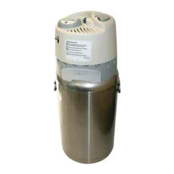
HELiOS Liquid Oxygen System Technical Manual Section HELiOS 300 GENERAL INFORMATION This section provides general information on the HELiOS 300 Portable liquid oxygen system (Figure 8-1). This information includes a product description; performance specifications; unpacking, installation, and repacking procedures; description of controls, indicators, and connectors;... -
Page 118: Performance Specifications
HELiOS Liquid Oxygen System Technical Manual For ambulatory use, the H-300 can be filled from the HELiOS Reservoir or from a Puritan- Bennett Companion Stationary. The H-300 typically fills in less than a minute and holds slightly less than one pound (.45 kg) of liquid oxygen. A full H-300 weighs 3.6 lbs. (1.6 kg). A simple mechanical display, based on the change in weight from full to empty, indicates liquid oxygen contents when the patient lifts the unit by a strap. -
Page 119: Unpacking, Installation, And Repacking
HELiOS Liquid Oxygen System Technical Manual UNPACKING, INSTALLATION, AND REPACKING Perform the following procedures when unpacking, installing or repacking a HELiOS 300 unit. 8.3.1 Unpacking Examine the shipping carton for damage. If the carton is damaged, or its contents are suspected of being damaged, photograph the damaged carton before the H-300 is unpacked. -
Page 120: Controls, Indicators, And Connectors
HELiOS Liquid Oxygen System Technical Manual Obtain the proper carton and insert for the H-300 you wish to package (Section 1.8, Accessories). Carefully place the carton insert around the H-300. Fold down the carton top flaps and secure the carton with packing tape. CONTROLS, INDICATORS, AND CONNECTORS The controls, indicators, and connectors that are used on the H-300 unit are shown in Figure 8-2. -
Page 121: Oxygen Outlet Connector
HELiOS Liquid Oxygen System Technical Manual 8.4.6 Oxygen Outlet Connector The oxygen outlet connector is one of a pair of barbed tubing connectors located on the front sidecover of the H-300. The patient attaches either tube of a dual-lumen cannula to this connector to receive oxygen flow from the unit. -
Page 122: Pre-Fill Inspection
HELiOS Liquid Oxygen System Technical Manual 8.5.1 Pre-Fill Inspection Perform the following procedure to visually inspect the H-300 and determine its opera- tional status before filling. Correct observed problems before proceeding to fill the unit. Visually inspect the H-300 unit for overall product integrity (for example, cracked or damaged components). - Page 123 HELiOS Liquid Oxygen System Technical Manual Figure 8-4: Positioning the H-300 for Filling WARNING Extreme cold hazard. Do not depress or disturb the plastic poppet in the center of the Reservoir fill connector. This will cause an uncontrolled release of liquid oxygen from the fill connector.
- Page 124 HELiOS Liquid Oxygen System Technical Manual When you notice a change in the sound of the venting gas, followed by the emission of a dense, white vapor around the Reservoir shroud, close the vent valve. Fill times may vary according to the temperature of the H-300 container before filling and the Reservoir pressure.
-
Page 125: Post-Fill Inspection
HELiOS Liquid Oxygen System Technical Manual Check the oxygen contents indicator to make sure the H-300 is filled to the desired level. To operate the contents indicator: (1) lift the H-300 by the contents indicator strap, (2) push the bottom backside of the unit so that it is straight up and down, and (3) observe the green indicator bar that displays the liquid oxygen contents level inside the clear window (Figure 8-7). - Page 126 HELiOS Liquid Oxygen System Technical Manual Securely attach one of the tubes from the dual-lumen oxygen cannula to the H-300 oxygen outlet connector (upper connector). Securely attach the other cannula tube to the sense connector (lower connector). Adjust the cannula on the face to receive oxygen comfortably (Figure 8-8).
-
Page 127: Maintenance
HELiOS Liquid Oxygen System Technical Manual Insert the flexible oxygen supply tube connector into the quick connect on the front of the H-300 and snap it in place. Locate the oxygen DISS nut and tailpiece assembly attached to the opposite end of the flexible oxygen supply tube. - Page 128 HELiOS Liquid Oxygen System Technical Manual TABLE 8-2 H-300 MAINTENANCE GUIDE ITEM ACTION Cleaning Remove the covers and clean the interior and exterior of each cover with a mild detergent and water. Wipe dry with a towel. Use cotton swabs in tight places. Use Scotch-Brite abrasive pad with detergent to lightly buff out scuffmarks.
-
Page 129: Helios 300 Theory Of Operation
HELiOS Liquid Oxygen System Technical Manual Section HELiOS 300 THEORY OF OPERATION This section describes the theory of operation for the HELiOS 300 Portable liquid oxygen system. Information presented in this section will help you understand how the HELiOS 300 system works. Items covered include functional descriptions of HELiOS 300 compo- nents and complete HELiOS 300 system operation. -
Page 130: Fill Connector/Quick Connect
HELiOS Liquid Oxygen System Technical Manual Conduction is the transfer of heat through a material, such as metal, by collisions of molecules in the material. Molecules at the hotter end of the material are moving faster than molecules at the cooler end. Heat is transferred from molecule to molecule as fast moving molecules run into the slower moving ones. -
Page 131: Vent Valve
HELiOS Liquid Oxygen System Technical Manual Female Body Female Male Poppet Poppet Cartridge Lip Seal Assembly Male Body Lip Seal Figure 9-2: Female Figure 9-3: Male/Female Fill Connector Fill Connectors Fully Engaged 9.1.3 Vent Valve The vent valve (Figure 9-4) is a lever-actuated, spring-loaded poppet valve that vents the inner container to atmosphere. -
Page 132: Relief/Economizer Valve
HELiOS Liquid Oxygen System Technical Manual 9.1.4 Relief/Economizer Valve The relief/economizer valve is a pressure-regulating device that combines the function of a primary relief valve and an economizer valve into one component (Figure 9-5). The primary relief valve establishes the system pressure of the H-300 when there is no oxygen flow through the oxygen outlet (“Standby”... -
Page 133: Secondary Relief Valve
HELiOS Liquid Oxygen System Technical Manual At Relief Valve Pressure Relief Valve Secondary Relief Valve To Flow Control Valve (Off) Vent Port Headspace Approaching Economizer Gas at Economizer Pressure 27 PSIG Valve (186 kPa) To Flow Control Valve At Economizer Pressure (On) To Flow Control Valve... -
Page 134: Warming Coils
HELiOS Liquid Oxygen System Technical Manual 9.1.6 Warming Coils There are two warming coils used on the H-300. Each warming coil is a heat exchanger that transfers heat from the surrounding atmosphere to the fluid contents inside the coil (Figure 9-7). The liquid withdrawal warming coil is a loosely wound coil of 1/8 in. aluminum tubing about 4.5 feet (1.4 meters) long. -
Page 135: Oxygen Supply Tube Quick Connect And Inline Check Valve
HELiOS Liquid Oxygen System Technical Manual inspiration ends. At the 4 setting, the volume of the bolus is 15 ml while the tail flow is 2 L/min. The flow control valve stores the metered oxygen until the demand valve senses the beginning of a patient inspiration. -
Page 136: Contents Indicator
HELiOS Liquid Oxygen System Technical Manual The inline check valve allows flow in one direction only through the oxygen supply tube quick connect. Oxygen from the Reservoir flows through the inline check valve and into the H-300 Portable. The check valve prevents gaseous oxygen in the H-300 from escaping through the quick connect when the oxygen supply tube is not used. -
Page 137: Portable Operation
HELiOS Liquid Oxygen System Technical Manual H-300 PORTABLE OPERATION The H-300 provides a uniform patient interface for breathing oxygen either in the comfort of home or while being active away from home. The patient fills the H-300 with liquid oxygen from the Reservoir to satisfy ambulatory oxygen needs. During periods of sleep or other sedentary activities at home, the H-300 provides the patient with gaseous oxygen from the Reservoir by means of a flexible oxygen supply tube. -
Page 138: Fill Termination
HELiOS Liquid Oxygen System Technical Manual 9.2.2 Fill Termination When the liquid oxygen level in the inner container reaches the end of the gas withdrawal/ vent tube (Figure 9-13), liquid oxygen is expelled through the vent circuit to atmosphere. The venting sound changes and the liquid oxygen creates a dense vapor cloud as it discharges under the Reservoir shroud. -
Page 139: Standby
HELiOS Liquid Oxygen System Technical Manual 9.2.3 Standby When the H-300 contains liquid oxygen, and there is no oxygen flow demand on the system, the pressure in the system increases and eventually stabilizes at the primary relief valve set point, approximately 27 psig (186 kPa). The pressure increases due to the Normal Evaporation Rate (NER) of the system. -
Page 140: Gaseous Oxygen Use - H-300 Filled With Liquid Oxygen
HELiOS Liquid Oxygen System Technical Manual 9.2.4 Gaseous Oxygen Use — H-300 Filled with Liquid Oxygen When the patient breathes from an H-300 that contains liquid oxygen, the oxygen flow can come from two locations within the H-300: the headspace above the liquid oxygen or the liquid withdrawal tube. - Page 141 HELiOS Liquid Oxygen System Technical Manual Once headspace pressure reaches 22 psig (152 kPa), the economizer valve spring force overcomes the opposing force created by the pressure acting on the valve diaphragm and closes down the valve. However, the economizer valve stays open just enough to allow the small flow of headspace gas created by the NER to pass through.
-
Page 142: Gaseous Oxygen Use - H-300 Connected To Oxygen Supply Tube
HELiOS Liquid Oxygen System Technical Manual 9.2.5 Gaseous Oxygen Use — H-300 Connected to Oxygen Supply Tube During periods of sleep or other sedentary activities, the patient connects the H-300 to the Reservoir oxygen supply tube. The oxygen that the patient breathes from the H-300 comes directly from the Reservoir gaseous oxygen outlet (Figure 9-17). -
Page 143: Helios 300 Performance Verification
HELiOS Liquid Oxygen System Technical Manual Section HELiOS 300 PERFORMANCE VERIFICATION This section provides testing information to verify H-300 performance for any of the following reasons: • To determine the cause of operational failure. • To check the unit’s overall system operation after the repair or replacement of a component. -
Page 144: Leak Tests
HELiOS Liquid Oxygen System Technical Manual 10.2 LEAK TESTS Liquid oxygen leakage from the H-300 unit in any amount is unacceptable and calls for the immediate removal from service of any such leaking unit. Minor gas leaks in connections and fittings will not affect system operation provided they do not exceed the Normal Evaporation Rate (NER) of the unit. - Page 145 HELiOS Liquid Oxygen System Technical Manual Use the liquid leak detector to test all fittings, connections, and joints. NOTE: Continually monitor the test pressure gauge while leak checking the H-300 to verify that the pressure in the system remains above 22 psig (152 kPa). Wet a finger with leak detector and lightly place it against the open end of the vent tube near the bottom of the unit (Figure 10-2).
-
Page 146: Pressure Hold Test (Alternate Leak Test)
HELiOS Liquid Oxygen System Technical Manual 10.2.2 Pressure Hold Test (Alternate Leak Test) Conduct the pressure hold test on an empty unit that has warmed to room temperature. Performing this test on an H-300 that contains liquid oxygen will yield inaccurate results. This test determines if the overall leak rate of the H-300 is excessive. -
Page 147: Secondary Relief Valve Test
HELiOS Liquid Oxygen System Technical Manual Figure 10-4: Pressure Test Setup Place one drop of leak detector on the R/E valve bronze vent port silencer disk (Figure 10-5). Slowly increase the gaseous oxygen source pressure until tiny, foam-like bubbles just begin to form on the surface of the silencer disk. Verify that the test pressure gauge reads 24-30 psig (166-207 kPa). - Page 148 HELiOS Liquid Oxygen System Technical Manual Set the H-300 bottle assembly on the portable test fixture. Stand the front side cover, with tubing still connected, next to the bottle assembly (Figure 10-1). CAUTION: Disconnect and clamp off the demand flow control valve oxygen inlet tube before performing the secondary relief valve test.
-
Page 149: Liquid Oxygen Functional Tests
HELiOS Liquid Oxygen System Technical Manual Slowly pressurize the H-300 by adjusting the oxygen source regulator. Verify that the secondary relief valve opens (audible hiss) at 75-85 psig (518-587 kPa). NOTE: If the secondary relief valve opens at a pressure slightly greater than 85 psig (587 kPa), reduce the oxygen source pressure to 50 psig (345 kPa). -
Page 150: Normal Evaporation Rate (Ner) Test
HELiOS Liquid Oxygen System Technical Manual 10.4.2 Normal Evaporation Rate (NER) Test The NER test measures the insulation efficiency of the H-300 liquid oxygen container. The test results express in pounds (kilograms) the amount of liquid oxygen lost (converted into gaseous oxygen and vented through the relief valve) in a 24-hour period. Perform this test when one or more of the following symptoms exist: Rapid loss of liquid oxygen contents from the container. - Page 151 HELiOS Liquid Oxygen System Technical Manual Set the H-300 bottle assembly on the portable test fixture. Stand the front side cover, with tubing connected, next to the bottle assembly (Figure 10-1). Allow time (typi- cally 30 minutes) for the unit to stabilize at primary relief valve pressure. The primary relief valve must be venting before continuing the test.
-
Page 152: Demand Flow Control Valve Test
HELiOS Liquid Oxygen System Technical Manual 10.4.4 Demand Flow Control Valve Test The demand flow control valve is an oxygen conserving device that, when set from 1 to 4, provides demand flow oxygen to the patient only during each inspiration. Settings less than 1 provide continuous oxygen flow. - Page 153 HELiOS Liquid Oxygen System Technical Manual Check the demand inspiration tailflow oxygen flow rate at settings 1, 1.5, 2, 2.5, 3, 3.5, and 4. Verify that the flows are within the acceptable range listed in Table 10-1. Disconnect the test flowmeter and the jet/venturi assembly from the connectors on the front side cover.
-
Page 154: Helios 300 Troubleshooting
HELiOS Liquid Oxygen System Technical Manual Section HELiOS 300 TROUBLESHOOTING Table 11-1 provides troubleshooting procedures for the H-300. This guide is not all- inclusive but is intended to serve as a general outline for solving operational problems. The table describes symptoms, identifies probable causes, and suggests corrective actions. - Page 155 HELiOS Liquid Oxygen System Technical Manual TABLE 11-1 (cont.) l l i f l i f l i f i t l . r i g i l . y t l l i f . r i l t u q i l o l l q i l...
- Page 156 HELiOS Liquid Oxygen System Technical Manual TABLE 11-1 (cont.) r i f s l i . y t l l i f l l l n i l n i t l i f . y t l i f i t r s l i .
-
Page 157: Helios 300 Service And Repair
HELiOS Liquid Oxygen System Technical Manual Section HELiOS 300 SERVICE AND REPAIR This section provides procedures for servicing the individual components of the H-300. Included are instructions, where applicable, for removal, disassembly, operational check, cleaning, inspection, adjustment, reassembly, and installation. WARNING Personal injury can occur from the uncontrolled release of pressurized gaseous and liquid oxygen. -
Page 158: Side Covers
HELiOS Liquid Oxygen System Technical Manual the opposite end to the H-300 bottom (sense) connector. Attach the reinforced end of the second tube to the jet/venturi shorter, right (oxygen inlet) connector as shown in Figure 12-1. Attach the opposite end to the H-300 top (oxygen outlet) connector. The jet/venturi longer, left (exhaust) connector must remain open. -
Page 159: Removal
HELiOS Liquid Oxygen System Technical Manual 12.2.1 Removal Place the H-300 on its side with the rear side cover facing you. Use a T10 Torx driver to remove the Torx screws from the rear side cover. Simultaneously pull both legs of the carrying handle away from the side covers. Separate the rear side cover about 3/4-in. -
Page 160: Disassembly - Rear Side Cover
HELiOS Liquid Oxygen System Technical Manual 12.2.4 Disassembly - Rear Side Cover CAUTION: Do not overstretch the contents indicator springs. Over stretching the springs will cause inaccurate contents indication. Remove and install the springs by grasping spring at the hooked end with a needlenose pliers. -
Page 161: Contents Indicator
HELiOS Liquid Oxygen System Technical Manual NOTE: When replacing the rear side cover, be sure to install a new warning label. Current side covers use seven Torx screws. 12.2.6 Installation Install the side covers by reversing the removal procedure. NOTE: Fully seat the carrying handle in the side cover handle bosses. The handle should lean toward the front of the H-300. -
Page 162: Removal
HELiOS Liquid Oxygen System Technical Manual 12.4.1 Removal Remove the side covers (Section 12.2.1). Use an adjustable wrench to hold the fill connector mounting bracket stationary. Use a 9/16-in. open-end wrench to remove the fill tube upper compression nut from the top of the fill connector (Figure 12-4). -
Page 163: Inspection
HELiOS Liquid Oxygen System Technical Manual Figure 12-6: Removing Fill Connector Assembly 12.4.2 Inspection Inspect the Kel-F poppet on the cartridge assembly for wear, damage, or embedded contaminants. Inspect the Teflon lip seal for wear or cracks. Inspect the female adapter for cracks or scratches on the tapered seal surface of the fill tube connector. - Page 164 HELiOS Liquid Oxygen System Technical Manual Use an awl or small screwdriver to remove the face seal from the female adapter (Figure 12-8). Figure 12-8: Removing Face Seal from Female Adapter Hold the female quick connect body with an 11/16-in. open-end wrench placed on the machined flats.
-
Page 165: Reassembly
HELiOS Liquid Oxygen System Technical Manual Figure 12-10: Removing Spiral Retainer Ring Remove the cartridge assembly (Figure 12-11). Figure 12-11: Cartridge Assembly 12.4.5 Reassembly NOTE: Cartridge assembly installation requires the use of P/N B-775394-00 female fill connector installation sleeve (marked "F") and P/N B-775392-00 inner installa- tion tool (marked "I"). - Page 166 HELiOS Liquid Oxygen System Technical Manual Figure 12-12: Inserting Spiral Retainer Ring into Female Installation Sleeve Firmly hold the fill connector and female installation sleeve together. Insert the rounded end of the inner installation tool (marked "I") into the female sleeve and push the retainer ring down until you feel it "click"...
-
Page 167: Installation
HELiOS Liquid Oxygen System Technical Manual Thread the lip seal retainer onto the large end of the female fill connector body and tighten to a torque of 35 lb/ft (511 n/m). Install a new female adapter seal on the small end of the female fill connector body. Thread the female adapter onto the body and tighten to a torque of 35 lb/ft (511 n/m). -
Page 168: Inspection
HELiOS Liquid Oxygen System Technical Manual Remove the side covers (Section 12.2.1). Disconnect the flexible vent tube from the barbed fitting at the vent valve outlet. Remove the torsion spring by lifting the curved end of the long spring arm off of the vent valve barbed fitting. -
Page 169: Service
HELiOS Liquid Oxygen System Technical Manual Inspect the vent valve lever, washer, and torsion spring for wear, cracks, or other damage. Temporarily install the barbed fitting and torsion spring on the valve (Figure 12-18). Make sure that the valve operates smoothly. The valve should return to the closed position when the lever is released. -
Page 170: Reassembly
HELiOS Liquid Oxygen System Technical Manual Remove the lever and Teflon washer (Figure 12-20). Torsion Spring Teflon Washer Valve Lever Barbed Fitting Figure 12-20: Disassembled Vent Valve Components 12.5.5 Reassembly Reassemble the vent valve by reversing the disassembly procedure. NOTE: Place the Teflon washer over the valve shaft and then align the hole in the valve shaft with the hole in the vent lever. -
Page 171: Removal
HELiOS Liquid Oxygen System Technical Manual 12.6.1 Removal Remove the side covers (Section 12.2.1). Remove the flexible urethane tube from the barbed fitting on the R/E valve outlet arm. Use a 1/4-in. open-end wrench to remove the barbed fitting. Use an adjustable wrench to hold the R/E valve inlet arm stationary (Figure 12-21). Use a 7/16-in. -
Page 172: R/E Valve Adjustment
HELiOS Liquid Oxygen System Technical Manual Tighten both compression nuts using a 7/16-in. open-end wrench on the nuts and an adjustable wrench on the corresponding R/E valve arms. NOTE: The R/E valve arms should face the container. Install the barbed fitting in the R/E valve outlet arm. Install the flexible urethane tube on the barbed fitting. - Page 173 HELiOS Liquid Oxygen System Technical Manual Figure 12-23: Test Pressure Gauge Setup Place one drop of leak detector on the R/E valve vent port silencer (Figure 12-24). Slowly increase the gaseous oxygen source pressure until tiny, foam-like bubbles first appear at the surface of the bronze vent port silencer disk. Verify that the test pressure gauge reads 24-30 psig (166-207 kPa).
- Page 174 HELiOS Liquid Oxygen System Technical Manual If the primary relief valve pressure is high, reduce the pressure in the H-300 to below 20 psig (138 kPa). Turn the primary relief valve adjustment screw a quarter turn counter clockwise (out) and repeat step 4. NOTE: To reduce pressure in the H-300, reduce the adjustment on the pressurizing source regulator.
-
Page 175: Secondary Relief Valve
HELiOS Liquid Oxygen System Technical Manual 14. If the economizer pressure is high, turn the economizer valve adjustment screw a quarter turn counter clockwise (out). Record pressure readings every five minutes until the pressure stabilizes. Repeat this step as needed to reach the specified range. 12.7 SECONDARY RELIEF VALVE The secondary relief valve is a poppet-type pressure control valve that acts as a safety... -
Page 176: Service
HELiOS Liquid Oxygen System Technical Manual 12.8.2 Service CAUTION: The demand flow control valve is manufactured to exacting tolerances and uses a number of small orifices. Ensure that hands, tools, and work table are clean when working with the valve. Do not allow liquids to enter the vent port located directly across from the valve inlet fitting. - Page 177 HELiOS Liquid Oxygen System Technical Manual Make sure that the H-300 has been tested for leaks before continuing. Set the demand flow control valve knob to 0 and fill the unit with liquid oxygen saturated at 22-27 psig (152-186 kPa). Let the system pressure stabilize for 10 minutes. Connect the jet/venturi test setup shown in Figure 12-27 to the H-300 sense (bottom) connector.
-
Page 178: Warming Coils
HELiOS Liquid Oxygen System Technical Manual If the Magnehelic gauge reads less than .038 in. H2O when oxygen flow first registers in step 6, adjust the demand flow control valve as follows. With the H-300 laying flat on the work table, position the top one third of the unit over the edge of the table. Insert a 3/32-in. -
Page 179: Installation - Liquid Withdrawal Warming Coil
HELiOS Liquid Oxygen System Technical Manual Pull the ends of the warming coil from their fittings and remove the warming coil. 12.9.2 Installation - Liquid Withdrawal Warming Coil Install the liquid withdrawal warming coil by reversing the removal procedure. NOTE: When installing a new warming coil, refer to Compression Fitting Makeup, Section 1.5.1. -
Page 180: Installation - Quick Connect
HELiOS Liquid Oxygen System Technical Manual Remove the 1/16-in. urethane tube from the barb on the quick connect. 12.10.2 Installation - Quick Connect Install the quick connect by reversing the removal procedure. NOTE: Make sure that the quick connect release button faces forward when installing the quick connect in the side cover. -
Page 181: Installation
HELiOS Liquid Oxygen System Technical Manual Use a 5/16-in. open-end wrench to hold the fitting on the 1/16-in. diameter stainless steel container tube stationary. Use a 7/16-in. open-end wrench to remove the liquid withdrawal warming coil compression nut from the fitting. Remove the warming coils and R/E valve as an assembly. -
Page 182: Helios 300 Illustrated Parts List
Section HELiOS 300 ILLUSTRATED PARTS LIST Section 13 contains six exploded view illustrations and related parts lists for the HELiOS 300 Portable. B-701693-00 Rev. C H-300 Illustrated Parts List - 13-1... - Page 183 HELiOS Liquid Oxygen System Technical Manual (This page is intentionally blank) 13-2 - H-300 Illustrated Parts List B-701693-00 Rev. C...
- Page 184 HELiOS Liquid Oxygen System Technical Manual , e l ¾ . n i e t i l l u , e l , n i , l e i n r ½ . n i e t i , t c e t i , t u .
- Page 185 SEE FIG. 13-2 FIGURE 13-1 H300 Portable H-300 Illustrated Parts List - 13-3...
- Page 186 HELiOS Liquid Oxygen System Technical Manual ½ . n i i r - , e l – ¼ . n i , t u – ¼ . n i l l i – ¼ . n i B-701693-00 Rev. C...
- Page 187 SEE FIG. 13-3 SEE FIG. 13-5 SEE FIG. 13-4 SEE FIG. 13-6 FIGURE 13-2 H300 Portable H-300 Illustrated Parts List - 13-4...
- Page 188 HELiOS Liquid Oxygen System Technical Manual t a l t l i t t i – . n i t t i – . n i – . n i c i l – . n i . n i –...
- Page 189 OBSOLETE FIGURE 13-3 H300 Portable H-300 Illustrated Parts List - 13-5...
- Page 190 HELiOS Liquid Oxygen System Technical Manual i l e – n i t – . n i i l e , e l – . n i , t u – . n i , l i – . n i , l i –...
- Page 191 FIGURE 13-4 H300 Portable H-300 Illustrated Parts List - 13-6...
- Page 192 HELiOS Liquid Oxygen System Technical Manual – o l f – t t i – B-701693-00 Rev. C...
- Page 193 FIGURE 13-5 H300 Portable H-300 Illustrated Parts List - 13-7...
- Page 194 HELiOS Liquid Oxygen System Technical Manual . y t l l i e t i , t u l l i , r e l l i , l a l l i l l i – e t i r t r B-701693-00 Rev.
- Page 195 FIGURE 13-6 H300 Portable H-300 Illustrated Parts List - 13-8...
Need help?
Do you have a question about the Tyco HELIOS Reservoir and is the answer not in the manual?
Questions and answers