
Subscribe to Our Youtube Channel
Summary of Contents for Parkeon WAYFARER 6
- Page 1 THE WAYFARER 6 ELECTRONIC TICKET MACHINE GENERIC SERVICE MANUAL (Publication Number 53923)
- Page 2 Parkeon. © Parkeon 2016 IMPORTANT NOTES This manual gives maintenance, service and repair information to cover all Wayfarer 6 ETM’s manufactured by Parkeon. The information in this publication refers generally to all Wayfarer 6 ETM’s. Paragraph 3.5 explains how particular models can be identified.
- Page 3 DISCONNECTED FROM THE ETM AND ANY OTHER MACHINES IN SYSTEM BEFORE CARRYING REPAIR, MAINTENANCE, OR SERVICE OPERATIONS UNLESS INSTRUCTIONS SPECIFICALLY STATE OTHERWISE. FAILURE OBSERVE THIS PRECAUTION RESULT CONSIDERABLE DAMAGE TO MACHINES. Publication Number 53923. Issue 3, March 2016 Wayfarer 6 Generic Service Manual...
-
Page 4: Table Of Contents
4.1.2 Connecting The Cable Assemblies ............... 25 4.1.3 Wayfarer 6 Tray Interface PCB Connections ........... 25 4.1.4 Wayfarer 6 ETM and Tray Final Operation ............. 30 MAINTENANCE & REPAIR - GENERAL INFORMATION ..........34 ....................34 RECAUTIONS ..................34 AINTENANCE EVELS .................. - Page 5 ................... 47 ID AND ANEL 7.2.1 Opening The Lid..................47 7.2.2 Removing The Wayfarer 6 Retaining Screws ........... 48 7.2.3 Removing The Lid and End Panel Section ............49 7.2.4 Removing The Smart Card Antenna PCB ............51 7.2.5 Removing The GPS and cable cover ............. 52 7.2.6...
- Page 6 Repairing Cable Assemblies ............... 98 EXPLODED VIEW AND RECOMMENDED SPARES LISTS ..........115 ........... 115 BOUT THE XPLODED IEW AND ECOMMENDED PARES ..........115 EQUENCE OF RAWINGS AND ECOMMENDED PARES Publication Number 53923. Issue 3, March 2016 Wayfarer 6 Generic Service Manual...
- Page 7 Figure 2. Model and Serial Number Label ..........20 Figure 3. Wayfarer 6 Installation and Clearance Dimensions ......21 Figure 4. Typical Wayfarer 6 Mounting Tray (generic version) ......23 Figure 5a. The Wayfarer 6 Mounting Tray Interface PCB ......26 Figure 5b.
- Page 8 Figure 62. Keyboard 20 Way Keys Cable Assembly ........113 Figure 63. Keyboard 40 Way Display Cable Assembly ......... 114 Figure 64. Wayfarer 6 ETM and Tray Exploded View (Generic) ...... 116 Figure 65. Ticket Paper Specification ........... 119 TABLES PAGE Table 1.
-
Page 9: Introduction
Please note that this publication has been written to cover all Wayfarer 6 ETM’s. To identify the machine in use refer to Paragraph 3.5 for information on model identification. - Page 10 Section 9 consists of two paragraphs. The first (9.1) gives some general information about the exploded drawings and Paragraph (9.2) shows the sequence of drawings and the recommended spares list for Wayfarer 6 machines. Publication Number 53923. Issue 3, March 2016...
-
Page 11: Audience
1.3 Audience This manual is intended for use by qualified service engineers and the technical staff of Parkeon Limited. 1.4 Related Documents Wayfarer 6 Generic Installation Manual - (Publication number 53922) 1.5 Revision History Number Date Author Comment August-2015 Production Release... -
Page 12: Terms And Abbreviations Used In This Manual
Silicon Serial Number TCP/IP Transmission Control Protocol Internet Protocol Volts Watts WLAN Wireless Local Area Network Wayfarer Transit Systems Table 1. List of Abbreviations Used in This Manual Publication Number 53923. Issue 3, March 2016 Wayfarer 6 Generic Service Manual Page 4... -
Page 13: Technical Data
1.5A polyswitch - main input. 500mA polyswitch-12V line protection. Display Ampire MODEL NAME: AM640480G2TNQW00H 5.7" COLOUR TFT-LCD RoHS COMPLIANT Passenger Display Gleichmann, GE-C1602B-TML-ET/R, 2 x 16 pixel backlit display. Publication Number 53923. Issue 3, March 2016 Wayfarer 6 Generic Service Manual Page 5... -
Page 14: Power Supply Cable
Conductors 7/0.25mm each core, tin copper, 22 AWG Impedance 54 Ohms Capacitance 115pF per metre - core to core 203pF per metre - core to screen Publication Number 53923. Issue 3, March 2016 Wayfarer 6 Generic Service Manual Page 6... -
Page 15: Ethernet Cable
Right angle, male, MMCX Antenna type 3G/4G, RoHS compliant, adhesive, Sequoia Technology Ltd, Cable 300mm long Please note: technical details are subject to change without prior notice. Publication Number 53923. Issue 3, March 2016 Wayfarer 6 Generic Service Manual Page 7... -
Page 16: General Description
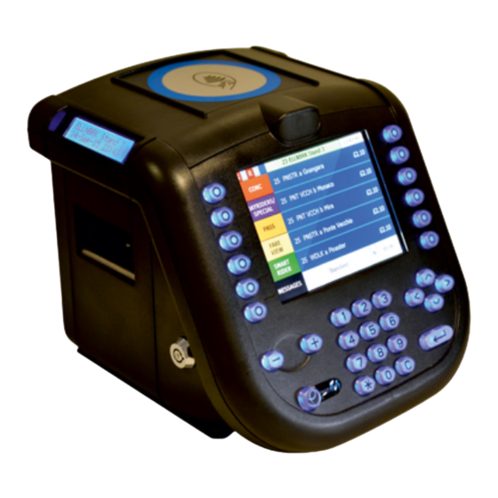
3 General Description The Wayfarer 6 ETM consisting of a printer unit and console provides bus drivers with leading edge technology for their interaction with passengers on their route and for communication with the depot. Some of the terms used are described below. -
Page 17: Wlan (Optional At Build)
ETM are stored in the memory of the machine. At the end of his shift, the driver returns the bus to the depot. The depot is the location where all information from the day’s transactions can be uploaded and analysed. Publication Number 53923. Issue 3, March 2016 Wayfarer 6 Generic Service Manual Page 9... - Page 18 WLAN is out of range. This manual describes in general terms all Wayfarer 6 ETM’s. For information about the access point refer to the documentation supplied with the unit.
-
Page 19: Figure 1. The Etm System And Components
Figure 1. The ETM System and Components Publication Number 53923. Issue 3, March 2016 Wayfarer 6 Generic Service Manual Page 11... -
Page 20: Physical Description
• The end panel with hinged lid • The tray The Wayfarer 6 can also be used as a driver’s console (i.e. – no smart card or printing) by omitting the printer assembly. In this application the end panel with lid mounts directly to the console. - Page 21 When in its operating position the Wayfarer 6 is mounted on to its mounting tray as described in Paragraph 4.1.4. The Wayfarer 6 ETM holes locate with location pegs...
-
Page 22: Detailed Description
The printer construction is such that very little maintenance is required to maintain a high level of operation. Publication Number 53923. Issue 3, March 2016 Wayfarer 6 Generic Service Manual Page 14... -
Page 23: Data Back-Up Module
SD cards should be used. Parkeon accepts no responsibility for customers who choose to use commercial SD cards. Viewing from the front of the Wayfarer 6, insert the SD card into the slot ensuring that the gold contacts are facing towards the display (away from the printer). -
Page 24: Printed Circuit Boards
Including the LCD display, there are up to thirteen printed circuit boards within the Wayfarer 6 ETM. The printer assembly contains the printer board, passenger display and top display PCB. The antenna PCB is located on the underside of the hinged lid. - Page 25 SAM expansion & Wifi (optional) GPRS board (optional) Keyboard I/F SKT1 Smart Card RF SKT5 3G/4G RF (optional) TOUCH_B Touchscreen (Direct plug-in) PL_TOUCH Touchscreen (Needs plug-in module) Publication Number 53923. Issue 3, March 2016 Wayfarer 6 Generic Service Manual Page 17...
- Page 26 The display is a non-repairable item whose electronics are supplied as an integral part of the display assembly. The display is physically mounted onto the keyboard PCB and plugs into PL6 of the keyboard PCB. Publication Number 53923. Issue 3, March 2016 Wayfarer 6 Generic Service Manual Page 18...
- Page 27 • Expansion Board (Optional) The Expansion board is for future use and has the following connections: Console Control Board Console Control Board Publication Number 53923. Issue 3, March 2016 Wayfarer 6 Generic Service Manual Page 19...
-
Page 28: Model Identification
A typical Wayfarer 6 consists of two assemblies: The ETM and the mounting tray. A typical label is shown in Figure 2. -
Page 29: Installation
4 Installation Figure 3 shows the area required to fit the Wayfarer 6 ETM, allowing space for access to the inside of the machine for maintenance purposes. Figure 3. Wayfarer 6 Installation and Clearance Dimensions Publication Number 53923. Issue 3, March 2016... -
Page 30: Installing The Wayfarer 6 And Tray
They will be sufficient to install all of the required ticket machines in their appropriate location. Wayfarer 6 mounting trays have fitted a tray interface PCB so connections should be wired up using the cables specified. The cable specifications are detailed in Section 2 of this manual. -
Page 31: Fitting The Wayfarer 6 Mounting Tray
4.1.1 Fitting The Wayfarer 6 Mounting Tray There is no requirement for the Wayfarer 6 and its tray to be electrically isolated from the vehicle chassis, therefore the mounting tray can be mounted directly to the vehicle metalwork or other suitable mounting medium. - Page 32 Find a suitable surface with sufficient space around it for the Wayfarer 6 to be located. Using an Allen key undo and remove the four M5 cap head screws that secure the mounting tray cover. Referring to Figure 2 offer the mounting tray against the surface and use as a template to mark the position of the four mounting holes.
-
Page 33: Connecting The Cable Assemblies
The screens must be attached at the Wayfarer 6 tray end only. A relay contact output (2A DC max) is provided on the Wayfarer 6 tray (PL6). It is up to the user to ensure that adequate fusing is provided when using these contacts. -
Page 34: Figure 5A. The Wayfarer 6 Mounting Tray Interface Pcb
Figure 5a. The Wayfarer 6 Mounting Tray Interface PCB Figures 5b and 5c on the following pages detail the location and function of the links on the Wayfarer 6 main control and the Wayfarer 6 printer PCB’s respectively. Publication Number 53923. -
Page 35: Figure 5B. The Wayfarer 6 Main Control Pcb (Links)
Figure 5b. The Wayfarer 6 Main Control PCB (Links) Publication Number 53923. Issue 3, March 2016 Wayfarer 6 Generic Service Manual Page 27... -
Page 36: Figure 5C. The Wayfarer 6 Printer Pcb (Links)
Figure 5c. The Wayfarer 6 Printer PCB (Links) Publication Number 53923. Issue 3, March 2016 Wayfarer 6 Generic Service Manual Page 28... -
Page 37: Figure 6. Generic Wayfarer 6 Installation Wiring Diagram
Figure 6. Generic Wayfarer 6 Installation Wiring Diagram Note:-The wiring diagram above shows all the items available for connection to the interface PCB. Where the interface is labelled (Optional) or (If Fitted) then it may not be included in your installation i.e. - it is customer specific. However options not used could be upgraded at a later stage. -
Page 38: Wayfarer 6 Etm And Tray Final Operation
4.1.4 Wayfarer 6 ETM and Tray Final Operation 1. Before the Wayfarer 6 ETM can be located onto the mounting tray the lock should be in the unlocked position as shown below. To unlock the Wayfarer 6 insert the key and turn 180 degrees in an anti-clockwise direction. - Page 39 D type socket Location pegs The Wayfarer 6 ETM back edge locating line The Wayfarer 6 ETM 37 way D type plug and mounting tray location peg holes are shown below. 37-way D type plug Location peg holes Rear View of ETM and mounting tray Publication Number 53923.
- Page 40 Push on lower edge, not on the screen. Once the Wayfarer 6 ETM is properly located, the 37 way D type plug is fully mated with the mounting tray 37 way D type socket and the mounting tray location pegs are located in the Wayfarer 6 ETM holes. The mounting tray rear is flush with the rear of the Wayfarer 6 ETM as shown on the previous page.
- Page 41 Turn key 180 degrees clockwise to lock Wayfarer 6 ETM to the tray Once the Wayfarer 6 ETM has been secured and locked on to the mounting tray the ETM is ready for use. The removal of the key indicates that the Wayfarer 6 is locked in place correctly.
-
Page 42: Maintenance & Repair - General Information
Take care to avoid pinching or trapping wiring when re-assembling the machine. 5.2 Maintenance Levels Parkeon define three levels of maintenance for their products, as follows: - • Level 1 Level 1 maintenance may be carried out by operators and is limited to those parts of the machine to which they are allowed access. -
Page 43: Tools And Equipment
• Level 2 Level 2 maintenance may only be carried out by engineers from Parkeon, their agents, or qualified technicians who have received proper training. Such work is limited to adjustments and replacement of sub-assemblies or some mechanical components. A basic tool kit is essential. -
Page 44: Obtaining Spare Parts
Firstly, identify the item description from the exploded drawing in Section 9. Then, using the description obtain the corresponding Parkeon part number from the recommended spares list. The new component may then be ordered from the... -
Page 45: Returning Machines Or Assemblies For Repair
If only part of a machine is being returned please state the machine's model and serial numbers, as this will help us to supply the correct replacement parts if this should be necessary. Publication Number 53923. Issue 3, March 2016 Wayfarer 6 Generic Service Manual Page 37... -
Page 46: Routine Maintenance And Servicing
Clean the casing with a lint-free cloth dampened with a mild non-abrasive detergent, and then wipe it dry using another such cloth dampened with water. Finally, dry the casing. Publication Number 53923. Issue 3, March 2016 Wayfarer 6 Generic Service Manual Page 38... -
Page 47: Display Cleaning
Finally refit the printer PCB. Publication Number 53923. Issue 3, March 2016 Wayfarer 6 Generic Service Manual Page 39... -
Page 48: Cleaning The Printer Roller
Gently clean the printer roller using a lint-free cotton bud dampened with isopropanol alcohol. The roller can be turned by finger pressure. When the roller is clean, re-lock the print head and refit by reversing these instructions. Publication Number 53923. Issue 3, March 2016 Wayfarer 6 Generic Service Manual Page 40... -
Page 49: Cleaning The Print Head
(i.e. -the no. of tickets) the machine prints on a daily basis. For removal instructions refer to Paragraph 7.4.5. Publication Number 53923. Issue 3, March 2016 Wayfarer 6 Generic Service Manual Page 41... -
Page 50: Servicing
Once the ticket paper appears at the ticket exit on the printer mechanism, tear off the protruding paper and close the lid. THE TICKET MACHINE IS NOW READY FOR OPERATION. Publication Number 53923. Issue 3, March 2016 Wayfarer 6 Generic Service Manual Page 42... -
Page 51: Figure 8. Changing A Paper Roll
Paper Slot Locking Lever (Print head) Round Paper Roll hole Paper Slot Square Paper Location Peg hole Paper Roll Paper Roll Figure 8. Changing a Paper Roll Publication Number 53923. Issue 3, March 2016 Wayfarer 6 Generic Service Manual Page 43... -
Page 52: Removing A Paper Blockage
Reload the paper as described earlier. Publication Number 53923. Issue 3, March 2016 Wayfarer 6 Generic Service Manual Page 44... -
Page 53: Special Repair Operations
However, if the terminal appears to be excessively worn or damaged it must be replaced. Publication Number 53923. Issue 3, March 2016 Wayfarer 6 Generic Service Manual Page 45... -
Page 54: Removal And Replacement Of Parts
If there is ever any doubt about how to fit a sub-assembly or assembly, compare the machine with a working machine of the same or similar type. Publication Number 53923. Issue 3, March 2016 Wayfarer 6 Generic Service Manual Page 46... -
Page 55: The Lid And End Panel
To open the lid, press the lid release button and then lift the lid. Hinge the lid upwards until it rests just past the vertical. Press here Hinge upwards Publication Number 53923. Issue 3, March 2016 Wayfarer 6 Generic Service Manual Page 47... -
Page 56: Removing The Wayfarer 6 Retaining Screws
7.2.2 Removing The Wayfarer 6 Retaining Screws The Wayfarer 6 is built in three main sections: • Console • Printer Assembly • Hinged lid and End Panel These three sections are all held together by retaining screws that pass through the sections from the rear to the front. Therefore the whole unit can be disassembled into three parts by removing these screws. -
Page 57: Removing The Lid And End Panel Section
ETM’s functionality. A full system contains smart card, GPS and 3G/4G cable connections. Hinged lid Printer Console Assembly End Panel Figure 12. Removing the End Panel / Hinged Lid Publication Number 53923. Issue 3, March 2016 Wayfarer 6 Generic Service Manual Page 49... -
Page 58: Figure 13. Accessing The Rear Of The Console
RF connector (SMA type) by gripping the nut and unscrewing anticlockwise. Finally, detach the static wire from the tag on the rear of the front console (refer to figure 45). Publication Number 53923. Issue 3, March 2016 Wayfarer 6 Generic Service Manual Page 50... -
Page 59: Removing The Smart Card Antenna Pcb
Re-fit the antenna PCB by reversing these instructions. SC RF M3 pozi fixing M3 pozi fixing screw screws (cover) (Antenna PCB) connector Cover Figure 14. Removing the smart card antenna PCB Publication Number 53923. Issue 3, March 2016 Wayfarer 6 Generic Service Manual Page 51... -
Page 60: Removing The Gps And Cable Cover
Note: There is an option for an external 3G/4G or GPS connector to be fitted in the end panel so that an external 3G/4G or GPS can be plugged in instead of the internal 3G/4G or GPS antenna. Publication Number 53923. Issue 3, March 2016 Wayfarer 6 Generic Service Manual Page 52... -
Page 61: Removing The 3G/4G (Internal)
3G/4G is refitted and not replaced. 3G/4G antenna 3G/4G antenna (Internal) cable and connector Figure 16. 3G/4G Antenna Options Publication Number 53923. Issue 3, March 2016 Wayfarer 6 Generic Service Manual Page 53... -
Page 62: Console Assembly
The console assembly does not have to be removed from the printer assembly to disassemble the front and rear mouldings of the console assembly. The rear Publication Number 53923. Issue 3, March 2016 Wayfarer 6 Generic Service Manual Page 54... -
Page 63: Removing The Front Moulding
Console Console front Control moulding 3G/4G iMX53 USB Hub processor board Console rear Interconnecting moulding cable assemblies Figure 18. Removing the Front Moulding Publication Number 53923. Issue 3, March 2016 Wayfarer 6 Generic Service Manual Page 55... -
Page 64: Removing The Imx53 Processor Board
The plastic tabs will lock the PCB into place once the connectors are correctly mated. Publication Number 53923. Issue 3, March 2016 Wayfarer 6 Generic Service Manual Page 56... -
Page 65: Removing The Usb Hub Board
The plastic tabs will lock the PCB into place once the connectors are correctly mated. Publication Number 53923. Issue 3, March 2016 Wayfarer 6 Generic Service Manual Page 57... -
Page 66: Removing The Console Control Pcb
Figure 44 for location and Figure 20 below for cable removal instructions. PL10 (Display) (Keys) CONNECTOR FLAT FLEXIBLE CABLE SIDE CONNECTOR FLAT FLEXIBLE CABLE SIDE Figure 20. Flat Flexible Cable Removal and Re-insertion Publication Number 53923. Issue 3, March 2016 Wayfarer 6 Generic Service Manual Page 58... -
Page 67: Figure 21. Removing The Sam Expansion And 3G/4G Pcb's
3G/4G fixings Fixings 4 off M3 nuts located and fibre under iMX53 washers board Figure 21. Removing the SAM Expansion and 3G/4G PCB’s Publication Number 53923. Issue 3, March 2016 Wayfarer 6 Generic Service Manual Page 59... -
Page 68: Removing The (Optional) Sam Expansion Board
Referring to Figure 22 and using a screwdriver undo and remove the PT pozi screw that secures the SSN PCB in place in the rear moulding. Replace the SSN PCB if faulty. Re-fit by reversing these instructions. Publication Number 53923. Issue 3, March 2016 Wayfarer 6 Generic Service Manual Page 60... -
Page 69: Removing The Display Assy From The Front Moulding
Referring to Figure 44 and Figure 23, disconnect the display connector from PL6 of the keyboard PCB. The display assy can now be removed from the keyboard. Publication Number 53923. Issue 3, March 2016 Wayfarer 6 Generic Service Manual Page 61... -
Page 70: Figure 23. Display & Keyboard Fixings
Once the cable is fitted correctly, re-fit by reversing steps 1-2. PT pozi screws – display fixings Display & Mounting Plate Keyboard PCB Display cable with Insulator Figure 23. Display & Keyboard Fixings Publication Number 53923. Issue 3, March 2016 Wayfarer 6 Generic Service Manual Page 62... -
Page 71: Removing The Display From The Mounting Plate
Figure 24. Wayfarer 6 Console Front Assembly Details 7.3.12 Removing The Display From The Mounting Plate Remove the display assembly from the front moulding as described in Paragraph 7.3.11. Using a small flat bladed screwdriver gently lever the four metal tabs enough that you can lift the display out from the mounting plate as shown below. -
Page 72: Removing The Keyboard Pcb / Keycaps / Keymat Assy
To prevent this, leave the keyboard PCB on the front moulding, whilst holding it against the moulding turn it over and then lift off the front moulding as shown in Figure 27. Publication Number 53923. Issue 3, March 2016 Wayfarer 6 Generic Service Manual Page 64... -
Page 73: Removing The Keymat And Keycaps
Detach it from the keyboard PCB by pulling lightly until it releases. Ensure that the keycaps remain attached to the keymat for reassembly. Re-fit by reversing these instructions. Publication Number 53923. Issue 3, March 2016 Wayfarer 6 Generic Service Manual Page 65... -
Page 74: Figure 27. Keymat And Keycaps Removal
Keymat silicon pips Keymat Keycaps Keyboard PCB Figure 27. Keymat and Keycaps Removal Publication Number 53923. Issue 3, March 2016 Wayfarer 6 Generic Service Manual Page 66... -
Page 75: Printer Assembly
If fitted, the paper roll can be removed if required as explained in Paragraph 6.2.1. Head Lock Lever Paper Roll Printer Base Moulding Printer PCB Figure 28. Printer Assembly (1) Rear View Publication Number 53923. Issue 3, March 2016 Wayfarer 6 Generic Service Manual Page 67... -
Page 76: Removing The Printer Pcb
Using a pozi screwdriver undo and remove the five PT screws securing the printer PCB to the printer base moulding. The board fixings are detailed in Figure 30. Publication Number 53923. Issue 3, March 2016 Wayfarer 6 Generic Service Manual Page 68... -
Page 77: Removing The Synch Disc
(square end inside the paper roll chamber) and then fit the E-clip to the outer shaft. Re-fit the hole plug. Referring to Paragraph 7.4.3 re-assemble the synch disc onto the paper spigot. Publication Number 53923. Issue 3, March 2016 Wayfarer 6 Generic Service Manual Page 69... -
Page 78: Figure 30. Wayfarer 6 Printer Base Unit
Fixing s Pass enger M2 pan pozi Display Screws Cover Hole Paper Plug Tension Delrin Fix ing Dis play Spring Ball Fixings M3 pan PCB A ssy Synch M4 pan pozi screw Wheel pozi screws (3 off) Synch Disc Synch Sensor Printer Base M oulding... -
Page 79: Removing The Paper Location Peg
PL2, PL3, PL6 and PL7 from the printer PCB. Referring to Figure 30, remove the three M4 fixing screws from the printer PCB side of the printer base, which secure the Wayfarer 6 printer mechanism to the printer base. -
Page 80: Figure 31. Dismantling The Wayfarer 6 Printer Mechanism
Figure 31. Dismantling The Wayfarer 6 Printer Mechanism Publication Number 53923. Issue 3, March 2016 Wayfarer 6 Generic Service Manual Page 72... -
Page 81: Figure 32. Printout Blade Fitting
Remove the two screws and washers (one at each end) from the ends of the guide rod and lift the rod clear - see Figure 33. Publication Number 53923. Issue 3, March 2016 Wayfarer 6 Generic Service Manual Page 73... -
Page 82: Figure 33. Paper Guide Fitting
With reference to Figure 30, carefully prise off (or cut) the star locking washer from the print head locking lever. Note: – it cannot be re-used. Publication Number 53923. Issue 3, March 2016 Wayfarer 6 Generic Service Manual Page 74... -
Page 83: Figure 34. Section Through Head Lock Lever
(under tension) to allow the web formation on the underside of the lever to locate past the locking spigot. As soon as this occurs, push the lever fully onto the shaft. Publication Number 53923. Issue 3, March 2016 Wayfarer 6 Generic Service Manual Page 75... -
Page 84: Figure 35. Print Roller And Motor Fitting
Figure 35. Print Roller and Motor Fitting (e) When refitting the roller, screw the threaded end of the roller finger tight into the motor shaft (left hand thread) and then Publication Number 53923. Issue 3, March 2016 Wayfarer 6 Generic Service Manual Page 76... - Page 85 This allows the top print head pivot pin to be removed without having to remove the head lock lever. Publication Number 53923. Issue 3, March 2016 Wayfarer 6 Generic Service Manual Page 77...
-
Page 86: Figure 36. Print Head And Lower Paper Guide
4mm long) from their insertion holes in the rear face of the front of the extrusion (the pins are not restrained and may have already dropped out once the head has been removed). Publication Number 53923. Issue 3, March 2016 Wayfarer 6 Generic Service Manual Page 78... -
Page 87: Figure 37. Print Head Pivot Pins Location
(e) The lower paper guide, complete with the paper out microswitch and cable assembly can now be removed. Publication Number 53923. Issue 3, March 2016 Wayfarer 6 Generic Service Manual Page 79... -
Page 88: Figure 38. Paper Out Microswitch Fitting
(2 OFF) CABLE ASSEMBLY SPRING PIN LOCATION LOWER PAPER GUIDE MICROSWITCH Figure 38. Paper Out Microswitch Fitting Retain the connector for use when the microswitch is replaced. Publication Number 53923. Issue 3, March 2016 Wayfarer 6 Generic Service Manual Page 80... -
Page 89: Passenger Display Assembly
With reference to Figure 40 and using a small pozi screwdriver, undo and remove the two M2 Pozi screws securing the passenger display cover. Lift off the cover. Publication Number 53923. Issue 3, March 2016 Wayfarer 6 Generic Service Manual Page 81... -
Page 90: Figure 40. Passenger Display Removal
Fixings Passenger Display pan pozi Cover Passenger Screws Display 2 x 16 Top Display Display PCB Assy Passenger Display Cable Figure 40. Passenger Display Removal Publication Number 53923. Issue 3, March 2016 Wayfarer 6 Generic Service Manual Page 82... -
Page 91: The Sd, Sam, 3G/4G Sim, Wifi & Usb Interfaces
Using a Tx10 screwdriver undo and remove the two M3 torx screws securing the access cover to the console. Lift out the access cover. Access Cover M3 Torx Access Screws Cover Cover Removed Publication Number 53923. Issue 3, March 2016 Wayfarer 6 Generic Service Manual Page 83... -
Page 92: Figure 41. Location Of Sd, Sam, Gprs Sim, Wifi & Usb Sockets
Figure 41. Location of SD, SAM, GPRS SIM, WIFI & USB Sockets Publication Number 53923. Issue 3, March 2016 Wayfarer 6 Generic Service Manual Page 84... -
Page 93: Removal And Insertion Of The Sd Memory Card
7.6.2 Removal and insertion of the SD Memory Card The SD memory card slot situated on the right-hand side of the Wayfarer 6 (looking from the front) provides the facility for data backup. The SD memory card is not intended for use on a daily basis to transfer data. It should only be used for emergencies to recover and transfer data. -
Page 94: Removal And Insertion Of The 3G/4G Sim And Sam's
Refer to Figure 43 shown below and the instructions that follow for SAM /3G/4G SIM removal and re-insertion instructions. Figure 43. 3G/4G SIM / Smart Card SAM Removal and Re-insertion Publication Number 53923. Issue 3, March 2016 Wayfarer 6 Generic Service Manual Page 86... -
Page 95: Wifi Module And Antennas
Referring to Figure 43 and looking at the front of the Wayfarer 6, insert the 3G/4G SIM or SAM Smart Card into the appropriate slot with the contacts facing you and the angled edge to the bottom left as shown in views 1 and 2. -
Page 96: Fault Finding And Testing
Note: Plugs, sockets, and other components on the circuit boards may be identified by referring to Figure 44. Publication Number 53923. Issue 3, March 2016 Wayfarer 6 Generic Service Manual Page 88... - Page 97 (PL10) on console control PCB. graphics displayed b. Display cable assembly faulty (PL6) on keyboard PCB. c. iMX53 Processor board faulty. d. Console control board faulty. e. Colour display faulty. Publication Number 53923. Issue 3, March 2016 Wayfarer 6 Generic Service Manual Page 89...
- Page 98 Antenna cable assembly faulty. d. Console control PCB faulty. a. Touchscreen or cable faulty. 8.2.16 18.Touchscreen not working. b. Console control board faulty. (If fitted) Publication Number 53923. Issue 3, March 2016 Wayfarer 6 Generic Service Manual Page 90...
-
Page 99: Types Of Faults
The printer is controlled using the USB hub. For it to function, the wire links on the printer control board must be inserted correctly. These are fitted by Parkeon. If you suspect they are fitted incorrectly or have been removed, contact Parkeon for correct configuration. - Page 100 “float” and will print one side of the ticket lighter than the other. 8.2.5 Paper Out Not Indicated Possible Causes: Paper out microswitch in printer faulty. Printer Control board faulty. Publication Number 53923. Issue 3, March 2016 Wayfarer 6 Generic Service Manual Page 92...
- Page 101 The sensor is a part of the printer PCB so if faulty then the printer control board must be replaced by a known serviceable item (Paragraph 7.4.2 refers). Publication Number 53923. Issue 3, March 2016 Wayfarer 6 Generic Service Manual Page 93...
- Page 102 If faulty then the printer control board must be replaced by a known serviceable item (Paragraph 7.4.2 refers). Publication Number 53923. Issue 3, March 2016 Wayfarer 6 Generic Service Manual Page 94...
- Page 103 The LED’s are powered from the console control board via the display and keys cables. With reference to Figures 61 and 62, check the continuity of the cable assemblies. If faulty then replace them with known working ones. Publication Number 53923. Issue 3, March 2016 Wayfarer 6 Generic Service Manual Page 95...
- Page 104 With reference to Figures 51 and 52, check the continuity of the antenna cable assemblies. The antenna and console control board can only be checked by direct substitution with known serviceable items. Refer to Paragraphs 7.2.4 and 7.3.6 respectively. Publication Number 53923. Issue 3, March 2016 Wayfarer 6 Generic Service Manual Page 96...
- Page 105 Paragraph 7.3.12. If none of the above rectifies the fault, check the console control board by substitution, paragraph, 7.3.6 refers. Publication Number 53923. Issue 3, March 2016 Wayfarer 6 Generic Service Manual Page 97...
- Page 106 The removal of terminals from Molex connectors may also be required when renewing a component that is using a shared connector. Refer to Paragraph 6.3.1 for details on how to remove an individual pin (crimp). Publication Number 53923. Issue 3, March 2016 Wayfarer 6 Generic Service Manual Page 98...
-
Page 107: Figure 44. Interconnection Diagram
Figure 44. Interconnection Diagram Publication Number 53923. Issue 3, March 2016 Wayfarer 6 Generic Service Manual Page 99... -
Page 108: Figure 45. Printer Static Cable Assembly
Figure 45. Printer Static Cable Assembly STEPPER MOTOR ORANGE B LACK B ROW N YELLO W STEPPER MOTOR 4 Way Molex MOTOR Figure 46. Printer Stepper Motor Drive Cable Assembly Publication Number 53923. Issue 3, March 2016 Wayfarer 6 Generic Service Manual Page 100... -
Page 109: Figure 47. Paper Out Microswitch Cable Assembly
Figure 47. Paper Out Microswitch Cable Assembly Publication Number 53923. Issue 3, March 2016 Wayfarer 6 Generic Service Manual Page 101... -
Page 110: Figure 48. Printer Data Cable Assembly
Figure 48. Printer Data Cable Assembly Publication Number 53923. Issue 3, March 2016 Wayfarer 6 Generic Service Manual Page 102... -
Page 111: Figure 49. Passenger Display Cable Assembly
Figure 49. Passenger Display Cable Assembly Publication Number 53923. Issue 3, March 2016 Wayfarer 6 Generic Service Manual Page 103... -
Page 112: Figure 50. Data Graphics Cable Assembly
Figure 50. Data Graphics Cable Assembly Publication Number 53923. Issue 3, March 2016 Wayfarer 6 Generic Service Manual Page 104... -
Page 113: Figure 51. Sc Antenna Pcb To Bh Cable Assembly
REAR MOULDING BOARD PL1 (front side) MMCX MALE SMB JACK RF COAX CABLE (RG178) 5OR RIGHT ANGLE BULKHEAD Figure 52. SC (Control board) to BH Cable Assembly Publication Number 53923. Issue 3, March 2016 Wayfarer 6 Generic Service Manual Page 105... -
Page 114: Figure 53. 3G/4G Antenna To Bh Cable Assembly
Figure 53. 3G/4G Antenna to BH Cable Assembly Publication Number 53923. Issue 3, March 2016 Wayfarer 6 Generic Service Manual Page 106... -
Page 115: Figure 54. 3G/4G (Control Board) To Bh Cable Assembly
(rear side) GPS ANTENNA CONSOLE REAR MOULDING (rear side) SMA MALE RF COAX CABLE (RG178) 5OR GPS ANTENNA BULKHEAD Figure 55. GPS Antenna to BH Cable Assembly Publication Number 53923. Issue 3, March 2016 Wayfarer 6 Generic Service Manual Page 107... -
Page 116: Figure 56. Gps (Control Board) To Bh Cable Assembly
REAR MOULDING (front side) MMCX MALE SMA FEMALE RF COAX CABLE (R G178) 5OR RIGHT ANGLE BULKHEAD Figure 56. GPS (Control board) to BH Cable Assembly Publication Number 53923. Issue 3, March 2016 Wayfarer 6 Generic Service Manual Page 108... -
Page 117: Figure 57. 37 Way Control Ribbon Cable Assembly
RS485_2+ X_IN X_IN2 EXP1 X_RS485COMMON +12V X_RS485- EXP2 X_RS485+ VAULT_OUT# -VE_SUPPLY +VE_SUPPLY -VE_SUPPLY +VE_SUPPLY -VE_SUPPLY +VE_SUPPLY -VE_SUPPLY +VE_SUPPLY Figure 57. 37 way Control Ribbon Cable Assembly Publication Number 53923. Issue 3, March 2016 Wayfarer 6 Generic Service Manual Page 109... -
Page 118: Figure 58. Console Speaker Cable Assembly
3 Way Molex Figure 58. Console Speaker Cable Assembly SERIAL NUMBER PCB CONSOLE CONTROL PCB PIN 1 SERIAL NUMBER CHIP DATA Figure 59. Serial Number PCB Cable Assembly Publication Number 53923. Issue 3, March 2016 Wayfarer 6 Generic Service Manual Page 110... -
Page 119: Figure 60. Printer Bh Cable Assembly
SOCKET SOCKET CONSOLE 15 WAY DTYPE CONTROL SOCKET BULKHEAD -VE_SUPPLY_PRINTER +VE_SUPPLY_PRINTER -VE_SUPPLY_PRINTER +VE_SUPPLY_PRINTER -VE_SUPPLY_PRINTER I2C1_DATA I2C1_CLK USB_EXT_VBUS USB_PRINTER_ID USB_PRINTER_D+ USB_PRINTER_D- Figure 60. Printer BH Cable Assembly Publication Number 53923. Issue 3, March 2016 Wayfarer 6 Generic Service Manual Page 111... -
Page 120: Figure 61. Keyboard 50 Way Display Cable Assembly
R_LCD_G4 R_LCD_G5 RESET# R_LCD_B0 R_LCD_B1 R_LCD_B2 I2C1_CLK R_LCD_B3 R_LCD_B4 R_LCD_B5 I2C1_DATA R_LCD_VSYNC R_LCD_DCLK R_LCD_DON R_LCD_HSYNC BACKLIGHT_ADJUST +3V3 +3V3 Figure 61. Keyboard 50 Way Display Cable Assembly Publication Number 53923. Issue 3, March 2016 Wayfarer 6 Generic Service Manual Page 112... -
Page 121: Figure 62. Keyboard 20 Way Keys Cable Assembly
CONTROL KEYBOARD KEYBOARD CONTROL MFP_D53/KEY_ROW0 MFP_D53/KEY_ROW1 MFP_D53/KEY_ROW2 MFP_D53/KEY_ROW3 MFP_D53/KEY_ROW4 MFP_D53/KEY_ROW5 +3V3 MFP_D62/KEY_COL0 MFP_D63/KEY_COL1 MFP_D64/KEY_COL2 MFP_D65/KEY_COL3 MFP_D66/KEY_COL4 MFP_D67/KEY_COL5 +3V3 Figure 62. Keyboard 20 Way Keys Cable Assembly Publication Number 53923. Issue 3, March 2016 Wayfarer 6 Generic Service Manual Page 113... -
Page 122: Figure 63. Keyboard 40 Way Display Cable Assembly
R_LCD_G1 R_LCD_G2 R_LCD_G3 R_LCD_G4 R_LCD_G5 R_LCD_B0 R_LCD_B1 R_LCD_B2 R_LCD_B3 R_LCD_B4 R_LCD_B5 ADJ_B/LIGHT ADJ_B/LIGHT_PWM R_LCD_DON R_LCD_VSYNC +3V3 R_LCD_HSYNC 0V/5V Figure 63. Keyboard 40 Way Display Cable Assembly Publication Number 53923. Issue 3, March 2016 Wayfarer 6 Generic Service Manual Page 114... - Page 123 Some Wayfarer 6 models however will have fewer parts than those shown in the generic machine. E.g.:- If the model has no smart card, GPS or 3G/4G components.
-
Page 124: Figure 64. Wayfarer 6 Etm And Tray Exploded View (Generic)
Figure 64. Wayfarer 6 ETM and Tray Exploded View (Generic) Publication Number 53923. Issue 3, March 2016 Wayfarer 6 Generic Service Manual Page 116... - Page 125 USB Plugin Hub PCB LF10707 iMX53 Processor Board,Way6 LF42890 SD Card (1Gb) standard LF10720 Console Control PCB standard, Way6 LF10714 Console Control PCB + GPS 73677 Grommet Publication Number 53923. Issue 3, March 2016 Wayfarer 6 Generic Service Manual Page 117...
- Page 126 SAM only Expansion PCB (3 SAM's) (optional) LF10717 Wifi only Expansion PCB (optional) LF10694 Expansion PCB (2 max) (optional) Table 5. Wayfarer 6 ETM Recommended Spares List (Continued) PART NUMBER DESCRIPTION Mounting Trays Power, Ign, RS232/485, Vault, Dig, SSN, Eth, USB, Relay, Debug...
-
Page 127: Figure 65. Ticket Paper Specification
PAPER TYPE TO BE KANZAKI KF50-HDA OR ARJO-WIGGINS 662/60 OR EQUIVALENT. THE HUB (PARKEON 72704) MUST BE RETAINED WITHIN THE ROLL SO AS TO RESIST UNAUTHORISED REMOVAL, USING THE TIGHTNESS OF THE WIND THE FORCE REQUIRED TO PUSH THE HUB FROM THE ROLL SHOULD BE IN EXCESS OF 20KG.
Need help?
Do you have a question about the WAYFARER 6 and is the answer not in the manual?
Questions and answers