
Subscribe to Our Youtube Channel
Related Manuals for OTARI MTR-90

Summary of Contents for OTARI MTR-90
- Page 2 CAUTION To prevent fire or shock hazard: Do not expose this appliance to rain or moisture. Do not remove cover. No user- serviceable parts inside. Refer servicing to qualified service personnel.
-
Page 3: Communication With Otari
The OTARI PRODUCTS are manufactured under strict quality control and each unit was carefully tested and inspected prior to shipment from our factory. If, however, some adjustments or technical support become necessary, replacement parts are required, or technical questions arise, please contact your nearest Otari dealer or write to: OTARI ELECTRIC CO., LTD. - Page 4 OTAR! MTR-90 MANUAL TABLE OF CONTENTS PAGE SECTION TOPIC INTRODUCTION OTAR! MTR-90 Master Tape Machine Using this Manual INSTALLATION Preliminary Inspection Assembly of Remote Control Box to its Stand 2-11 Assembly of Remote Control Box and Auto Locator 2-15 Connections ·...
-
Page 5: Shift Left
OTAR! MTR-90 MANUAL TABLE OF CONTENTS (continued) PAGE SECTION TOPIC Use of Variab le Speed Mode 6.10 Use of an External Speed Reference AUTO LOCATOR General Tape Time Locate Time Stopwatch Keyboard Nu merals Shift Left Shift Right & Load... - Page 6 OTARI MTR-90 MANUAL TABLE OF CONTENTS (continued) PAGE SECTION TOPIC 10-5 10.8 Cleaning Lubrication & 10-6 10.9 Removal Repacement of Motor & Drive Amp Output Assembly SP ECIFICATIONS 11-1 11.1 Tape Transport 11-1 11. 2 Electronics 11-2 11.3 Physical 11-3 11.
- Page 7 OTARI MTR-9O MANUAL LIST OF ILLUSTRATIONS PAGE FIGURE TITLE 1 -3 MTR-9O Master Ta p e Recorder. 1- 4 Ta p e Trans p ort Controls. 1- 4 1- 3 Cue Button and Slider. 1- 5 1- 4 VU Meter Panel.
- Page 9 OTARI MTR-90 MANUAL LIST OF ILLUSTRATIONS ..(continued) TITLE PAGE FIGURE 12-16 12-4 Tension Arm Assembly. 12-17 12-5 Reel. Assembly. Heat Sink Assembly for Capstan and Reel Motors. 12-18 12-6 12-19 12-7 Control Assembly. 12-20 Control Chassis Assembly. 12-8 12-21 12-9 24 Channel Amp Chassis Assembly.
- Page 11 when the unit is switched between play and stop or fast winding modes, although dip-switches on the transport control circuit permit these logic functions to be modified to suit the preference of the user. High quality transformers and XL-type connectors afford plenty of common mode rejection, and avoid ground loop-induced hum.
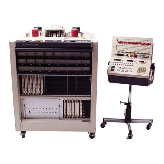
- Page 12 FIGURE 1-1. MTR-90 Master Tape Recorder Page 1-3...
- Page 13 • ---- �- FIGURE 1-2. Tape Transport Contr ols. FIGURE 1-3. Cue Button and Cue Slider Page 1-4...
- Page 14 --- --- ----- • -------- -------- �1 -:,• ,�. ] FIGURE 1-4. VU Meter Panel (24-track or 16/24 track version). FIGURE 1-5. MTR-90 Upper an d Lower Circuit Card Cage s. Page 1-5...
- Page 15 FIGURE 1-6. Removal of PCB from Upper Card Cage (24-track version illustrated). FIGURE 1-7. MTR-9O Power Swi tch, Fuses, and Pilot Lamps. CAUTION: NEVER ATTEMPT TO OPERATE THE MTR-9O IF EVEN ONE OF THESE PILOT LAMPS DOES NOT LIGHT WHEN PO WER IS SWITCHED CHECK THE FUSE, REPLACE IF NECESSARY, OR CORRECT WHATEVER PROBLEM MAY EXIST.
- Page 16 FIGURE 1-8. Audio Input and Out put, Remote Control, Auto Loca tor and Power Connections on MTR-9O Rear Panel. ,.,_....• • a e ■ n a ■ rt -□ • □□□□ □ □ BGEJ FIGURE 1-9. Remote Control Box (standard) and Auto Locator (optional).
- Page 18 Withdraw the #3 board and examine the 4-rocker DIP switch (SW-1 on Figure 2-1 ). The #1 and #4 switches should be On (#2 and #3 settings are irrelevant). This sets the logic so that when tape is stopped or in fast wind, and channels are in Sel-Rep mode, their output signal is derived from the input electronics rather than the record head and sync amps.
- Page 19 Withdraw the #6 board and examine the DIP switch (SW3 on Figure 2-2). This 4-station slide switch sets the Reproduce EQ for either NAB or IEC standard at 15 ips, and AES or IEC at 30ips; see Figure 2-2, and chart below. C1tC11 :!:!��...
- Page 22 CAUTION: When closing this back panel, use care to ensure that no wires are pinched between the panel and the MTR-90 chassis. Lift the panel with one hand on each side so it closes symmetrically and without strain.
- Page 26 Examine the square black carrier blocks. Notice that one side of the part is labeled "A" near the center, and the other "B". Press the blocks onto the mounting flanges so the "B" side of each block is adjacent to the Remote Box. Insert the remaining brass bearing flanges in each of the carrier blocks.
- Page 27 ASSEMBLY OF REMOTE CONTROL BOX AND AUTO LOCATOR TO COMMON STAND Place the CB-104 Remote Control Box (Remote Box) panel-forward and upright on a flat work surface. Connectors should be facing away from you. Locate the two large aluminum V-brackets. Using 3 allen head cap screws per bracket, attach one V-bracket to each side of the Remote Box.
- Page 29 NOTE: In both illustrations below, the carrier block orientation is the same. The flat side is up, and the thinner flange faces the V-bracket. Figure 2-9A. Assembly of desk top stand to Remote Box and Auto Locator. Figure 2-9B. Assembly of roll-around stand to Remote Box and Auto Locator.
- Page 30 REMOTE CABLE FOR TRANSPORT LOGIC: (25-pin Cannon D connectors). The male end of the cable plugs into the rear of the MTR-90, and the female end into the Remote Box. The mating chassis mounted connectors have a clip lock on each side that must be spread open when inserting the cable connectors, then snapped forward to lock the cable in place.
- Page 31 MTR-90, as labeled on its rear panel. Also, do not plug in the power cord until you check to make sure the MTR-90 power switch is turned Off. This rocker switch is located on...
- Page 32 Connect the buss outputs from your console to the MTR-90 Input connectors (10 kohms load impedance, floating), and connect the MTR-90 Outputs (40 ohms source impedance, floating) to the line inputs of your console. To avoid h um-inducing ground loops, be sure to follow a sensible grounding scheme,...
- Page 35 POWERING UP. Locate the POWER switch (behind the front door of the MTR-90 at the left side and near the bottom), turn it On (press upper half of rocker switch) and observe carefully to ensure the following conditions are present:...
- Page 38 LOAD THE SERVOS. Press the STOP button. Now it will be more brightly illumi nated than all the other tape motion pushbuttons, and both swing arms should move to approximately mid-travel (centered). The reel servos are now energized, keeping the tape under constant tension.
- Page 39 NORMAL CUE MODE. Center the Cue Lever (in front of the head assem bly), and press the CUE button, which should then light up brightly. Move the Cue lever to the right; the farther to the right the lever is moved, the faster tape should wind onto the takeup reel.
- Page 45 ...__ MASTER OUTPUT DRIVE SELECTION. When you wish to switch the entire machine's output to one of the three possible modes, instead of actuating 24 separate levers, you can use the master ALL INPUT [3], ALL SEL-REP [4] or ALL REPRO [5] pushbuttons . They override the indiv...
- Page 48 CLEANING THE TAPE PATH It is important to regularly clean the route along which the tape travels. Oxide and dirt will shed from tape and accumulate on these parts, causing a build-up that can create slippage, degrade frequency response, and accelerate tape wear. CAUTION: Never use any metallic item or abrasive to clean the heads or other tape guidance parts.
- Page 50 SYNC AMP ALIGNMENT Engage the ALL SEL-REP button on the Remote Box. SAFE should still be engaged. Rewind the test tape, press the PLAY button, and locate the 1 kHz reference tone . Observe the VU meters, which should indicate O VU. If any do not, adjust the SYNC GAIN control on the correspondingly numbered audio boards as required.
- Page 54 (FEEDS ALL CHANNELS) RECORD HEAD DRIVER 400-500 mV P-P � - o ERASE HEAD (ERASE CURRENT•95mA) Figure 4-5. MTR-90 block diagram showing a u dio levels, 24-channel model. (Based on 1 kHz signal, NAB EQ, 30 ips speed.) Page 4-9...
- Page 56 RECORD HEAD AZIMUTH Thread a blank tape on the transport; a dual-trace oscilloscope should be connected to the MTR-9O's channel #2 and #23 outputs (channels #2 and #15 on 16-track heads). The Remote Box should be set to All Repro mode. Prepare to record a test tone by setting channels #2 and #23 (or #15) to Ready mode, and disengaging the ALL SAFE button.
- Page 58 ---... a. hold swing arm up to remove the guard. b. release arm to lift of f cover plate. Figure 5-2. Transport cover plate removal. Page 5-3a...
- Page 60 SWING ARM TRAVEL (Refer to Figure 5-3.) A finger on the linkage of each swing arm restricts swing arm travel when it contacts a felt-pad ded U-bracket screwed to the deck plate. Two phillips screws go through oval holes in the bracket; the extremes of swing arm travel may be adjusted by loosening these screws and sliding or rotating the U-bracket.
- Page 61 TAPE ARMING SOLENOIDS NOTE: Before continuing, you should first have performed the procedures outlined in Section 5.4. (Refer to Figure 5-4.) The tape arming solenoid is the smaller one (the solenoid nearest the front of the deck plate) of the pair associated with each swing arm. It can be moved back and forth after loosening the two phillips screws that secure it to the deck plate.
- Page 65 These adjustment nuts are accessible either by opening the meter panel, or by removing the two side cover panels from the MTR-90. Loosen the double nut by holding the portion closest to the support bracket stationary, and unscrewing the other half.
- Page 68 5.1 1 REEL TENSION SERVO The following adjustments are made with the deck plate installed, but without tape. Refer to Figure 5-8. UPPER AND LOWER LIMIT ADJUSTMENT Turn power off, and remove the REEL CONTROL circuit board (board #1) from the lower card cage. Visually set all trimmers to the center of their travel.
- Page 69 Repeat the procedure for the supply swing arm, adjusting the SUP POS trimmer on circuit board #1 until the supply reel motor reverses direction. Hold the takeup swing arm all the way up to the top of its travel (toward the rear of the deck plate), and adjust the T.UP GAIN trimmer (sixth from top on circuit card #1) until the takeup reel motor just begins to slow down.
- Page 71 Reel motor ceram ic power resi stor locat ion beneat h Fi gure 5-9. transport (sup ply side shown from front). Page 5-16...
- Page 72 5.12 CAPSTAN SERVO NOTE: In this Section of the manual, refer to the following illustrations: Figure 5-10 for capstan tachometer adjustment, Figure 5-11 for capstan control circuit card adjustments, Figure 5-13 for miscellaneous capstan waveform references. NOTE: The circuit board edge connectors have 50 pins on each side of the board.
- Page 74 VR 2 PLAY DAMP VR l PLAY GAIN 3 FAST GAIN 4 FAST DAMP IC 18 IC 12 IC 13 VR 5 IC 4 CONN. AB PIN 5 Figure 5-lla. Capstan control circuit board, adjustments and check points Page 5-19...
- Page 75 F.FWD, REWIND SPEED TRIMMING VR 1 PLAY GAIN VR 2 PLAY DAMP VR 3 FAST GAIN FAST DAMP VR 7 CUE STOP POS. AD J TP 7 GROUND TP 8 VR 8 F.FWD, REWIND SPEED ADJ. F.WIND START TIME TP 6 TP 2 TACH.
- Page 76 44 kHz). 5.13 FAST WIND MODES FAST WIND GAIN The Capstan Control board should still be attached to the extender board, and power should be on. There should not be any tape loaded on the transport. Arm the servos by pushing both swing arms to the top of their travel and pressing the STOP button.
- Page 78 Appro><. 600 nanoseconds __n_Jl__ at IC 12, pin 10 104 micros conds (208 /.I sec for low sp a) Clock for play mode (high speed), at IC 12, pin 10. Approx. 5V P-P sine wave b) Tach signal, at connector AB 3,5. jitter Adjust VRS for a 50% duty cycle (equal width positive &...
- Page 80 (Figure 5-13, continued) +30V -------------------------- - 30 V ------------------------- i) DC amplifier output, at connector AB 31.(TPl) at IC13, pin 3 at IC 13, pin 2 (TP2 ) at IC 13, pin 6 j) Direction sensor output with tape moving forward (play, fast forward, forward cue).
- Page 82 GENERAL The following procedures are based on the assumption that the MTR-90 has been instal led and checked for pr oper functions, as per Sections II and III, and that it has been properly aligned as per Sections IV and V of this manual.
- Page 85 To cease recording on all tracks, press the STOP button, the PLAY buttons, or the ALL SAFE button. To cease recording on only certain tracks and continue recording on others, move their READY/SAFE levers down to Safe position. PLAYBACK OF INITIAL TRACKS Rewind the tape.
- Page 86 Press the PLAY and RECORD buttons to begin the overdub. You will now be monitoring the input on those tracks being recorded, and the tape from the record head and sync amps on those tracks not being recorded. To end the overdub, press the STOP button. As a further precaution, engage the ALL SAFE button, preventing any accidental erasure of those individual tracks set to Ready...
- Page 90 SECTION VII. AUTO LOCATOR GENERAL The OTARI CB-107 Auto Locator is designed specifically for the MTR-90. It contains a microcomputer for sophisticated, precision control of tape motion without overshoot. A tape time memory stores up to 10 cue points (11 cues if zero search is also...
- Page 92 To Zero the Tape Time at the location of the tape currently in front of the heads, press the adjacent RESET button [2]. To offset the A uto Locator Tape Time readout from the MTR-90 readout, select a Locate Time [3] and press the Shift Left button [10].
- Page 96 Record mode. To end ("abort") a Shuttle, press STOP, REWIND, or FAST FORWARD on the Auto Locator [20], their counterparts on the Remote Box and MTR-90, or the PLAY or RECORD buttons on the Remote Box or MTR-90. 7.15 AUTO REWIND...
- Page 100 The PLAY button will then brighten (SHUTTLE is still bright), and tape will play ahead to the Locate Time. This cycle will continue indefinitely until you press STOP, REWIND, or FAST FORWARD. ILLEGAL COMMANDS Stop the tape. Enter a Locate Time that is earlier than the displayed Tape Time, and press the SHUTTLE button.
- Page 102 SECTION VIII. 16/24 TRACK CONVERSIONS GENERAL The OTARI MTR-90 may be ordered in any of three configurations, 16 track-only, 16 track wired to accommodate 24 tracks (16 track convertible), or 24 track; this section of the manual deals only with changing between 16 and 24 track formats on the later two versions.
- Page 104 SECTION IX. CIRCUIT DES CRIPTIONS NOTES: 1. Pertinent schematic diagrams in the drawing package accompanying this manual are referenced after each subtitle (alternate drawing numbers also given). 2. Each circuit board has its own individual power supply regulation to provide the necessary voltages. PLAYBACK HEAD AND PREAMP [Drawing Ref.
-
Page 105: Input Circuitry
Transformer T 101 steps up the head's output signal and feeds the signal to matched transistor pairs Qll3 and Qll4 for preamplific ation (Q 129;1ater model). Second stage is provided by QllS and Qll6, (IC104;later model) and a low impedance output is given by Qll7/Qll8. 15 ips EQ is switched ON by Q 122, and 30 ips EQ is switched ON by 120. - Page 106 emphasis is provided by IC 205A, and adjusted by 10-turn 10 kohm potentiometer VR 204. IC 205B serves as a differential mixer for 15 ips EQ. 30 ips high frequency pre-emphasis is provided by IC 204A, and adjusted by 10-turn 10 kohm potentiomer VR 203. IC 204B serves as a differential mixer for 30 ips EQ.
- Page 108 9.11 CAPSTAN CONTROL BOARD [Drawing Re f. PB-43K (PB-9A269)] The MTR-90's capstan motor system, in ad dition to providing play mode tape metering, also controls the tape speed in fast for ward and rewind modes. Since the reel motors merely "follow" the...
- Page 110 SECTION X. MAINTENANCE 10.1 GENERAL The OTARI MTR-90 requires very little maintenance, other than routine electronic alignment to different tape batches, cleaning, and demagnetization. In ad dition to these day-to-day maintenance procedures, there are a few items that wil l benefit fr om occasional cleaning and/or lubrication.
- Page 111 10.2 REMOVING AND REINSERTING PRINTED CIRCUIT' BOARDS The printed circuit boards, alternately referred to in this manual as circuit cards, in the MTR-90's upper and lower card cages are equipped with convenient levers that uniformly distribute pres sure when withdrawing the cards.
- Page 112 NOTE: The entire brake lever and pad are available as an assembly from OTARI. If so ordered, disregard steps 6 and 7 below. Remove the old brake pad carefully, using a razor blade and solvent (MEK, acetone, lacquer thinner, etc.).
- Page 114 Refer to Section 4.3 for cleaning the tape path. There are only a few other areas that should be checked periodically for dirt. The MTR-90 motor and guide roller bearings are permanently lubrica ted so they do not require oiling. HEAD SHIELD SCREW Perform this procedure once every 6 months, or if the sheilds become noisy or move erratically.
- Page 115 10.9 REMOVAL AND REPLACEMENT OF MOTOR DRIVE AMP OUTPUT ASSEMBLY (Numbers in brackets refer to callout s in the exploded view drawing, Figure 12-6.) This assembly, located beneath the deck plate between the reel motors, is enclosed by an air duct [2] and cooling fan [l]. Power transistors and po wer resistors are mounted on three heat sinks [5] inside the air duct.
- Page 116 SECTION XI. SPECIFICATIONS 11.1 TAPE TRANSPORT TAPE WIDTH AND TRACKS: 2-inch (50.8 mm) 16 tracks and/or 2-inch 24 tracks. REELS SIZE: Up to 14 inches diameter (35.6 cm), AAB h�. HEADS: Plug-in head blocks with full access to independent head azimuth adjustment. DRIV E SYSTEM: Pinch-rollerless direct drive capstan system with ±20% speed control.
- Page 117 AMPLIFIER CLIPPING: +28 dBm. HEADROOM: 24 dB. EQUALIZATION: @ 30 ips, AES or IEC (CCIR ), switchable on repro. @15 ips, NAB or IEC (CCIR ). Record EQ to be specified at time of order. BIAS FREQUENCY: Record, 246 kHz: Erase, 123 kHz.
- Page 119 If there seems to be a dis crepancy between the drawings herein and your MTR-90, contact OTARI; we assume no liability for improper servicing due to ch anges and improvements which we may make that subsequently render certain of these documents obsolete.
-
Page 120: Parts Lists
12.2 PARTS LISTS These key numbers which precede the parts descriptions refer to callouts in the exploded views in section 12-2. Each parts list is associated with one exploded view drawing, as indicated by the number in brackets after the parts list title. HEAD ASSEMBLY [l]: No. - Page 122 TENSION ARM ASSEMBLY [ 4 ]: Parts No. Notes No. Description KA6A004 Cap, Tension Roller Upper Guide, Tension Roller KA6A003 Washer, Wave F78-8 BA22280L Bearing Ball KA6A001 Roller, Tension KA6A002 Under Guide, Tension Roller KA6A005 Shaft, Tension Roller KA6A014 Left Side Protector A, Tape KA6A021 Collar, Screw...
- Page 124 CONTROL ASSEMBLY [7]: No. Description Parts No. Notes Knob, Slide VR KN1041 Spring, Clamp GS5017 Base B, Housing KHOF029 Protector A, Switch CB22809 Push Switch WH11018 Lamp, 28 V LU2007 Cap, Switch, Rwd or F. Fwd KN2042 Cap, Switch, Stop KN2040 Cap, Switch, Play KN2041...
- Page 126 CO NTROL CHASSIS ASSEMBLY [8]: (Continued) No. Description Parts No. Notes Connector, EI Housing 8P CN408066 Connector, EI Housing 9P CN409067 Connector, EI Housing lOP CN410068 Connector, EI Housing llP CN412069 Connector, Socket Contact CN7B-053 Panel, Bias Control P.C. Board PB14E01 Panel, Time Base P.C.
-
Page 127: Power Supply Assembly
24 CHANNE L AMP CHASSIS ASSEMBLY [9]: (Continued) ..No. Description Parts No. Notes Connector, Housing CN403061 Connector, Housing CN405063 Connector, EI Housing CN408066 Connector, Housing 12P CN412069 Connector, Contact CN7B-052 AMP CHASSIS REAR PANEL ASSEMBLY [10]: Trans Ass'y, Output ZA-91T Panel, Output Transformer ZA91G015... - Page 130 POWER SUPPLY ASSEMBLY (11'] - LATER MODEL- (Continued) Parts No. Notes No. Description Capacitor Cl33348M Capacitor Cl33350M Capacitor Cl33349M Capacito r Cl22204M Transint Surge Absorber PN-0142 Stud KZ7B229 Relay RY3DA045 Angle, Capacitor DS1U013 Stopper, P.C.Board DS1U022 Panel, Connector DS1U006 Angle B, Front Panel DS1U020 Angle A, Front Panel DS1U019...
- Page 135 BS4 x 6 Head A ssembly. Figure 12-1. Page 12-13...
- Page 136 PS3x6 Figure 12-2. Capstan Assembly. Page 12-14...
- Page 137 es3x10 BS4x8 Figure 12-3. Tape Lifter and Shield Assembly. Page 12-15...
- Page 138 BS 4x 8 Figure 12-4. Tension Arm Assembly. Page 12-16...
- Page 142 � I-'· I\.) ti:, I\.) I\.) F4 x6 I-'· :i::- S 3x6 � � � · -0,- .:::- y : � r<' � .,�...
- Page 148 ff 0 3 t16 � TS3"6 � � � � TS3x6 � ,,.,,."1 .,,. ,,. -,� 1-xj I-'· � � "'Cl •, �� < .t:- , ... C3'c8 45 44"" C3'8 :><...
Need help?
Do you have a question about the MTR-90 and is the answer not in the manual?
Questions and answers