Table of Contents
Advertisement
Quick Links
Advertisement
Table of Contents

Related Manuals for Ground Control CP4

Summary of Contents for Ground Control CP4
- Page 2 Package Contents Product Name Image CP4-NA-LTE Vehicle Recorder SD and SIM cards pre-inserted (if applicable) Power Cable BAT(+), IGN+, BAT(-) Remote Controller (Panic Button) with 3M adhesive Video Output Cable and I/O triggers Camera Input Cable (4x Aviator input for Ch. 1-4)
- Page 3 Torx Screw (x2) and Torx screwdriver Velcro tape (x4) and Wire Splice clip (x5) 3G/LTE Antenna Locking Enclosure/Mounting Bracket (Optional Accessory) pg. 4...
-
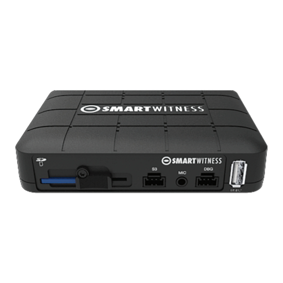
Page 4: Front View
2. CP4 Hardware Overview Dimensions 3.55” Built-in microphone 4.75” Front View Debug Port Serial Port (No Use) Microphone SD Card Slot Torx Screw USB Input 2 Input Rear View LTE Antenna Connectors Camera Input GPS Input USB Input... -
Page 5: Installation
3. Installation: Park the vehicle on a flat service. Turn of the engine before installing the CP4. The SD card and SIM is usually pre-inserted, but if it’s not, you should be notified by the service provider and have been provided SIMs/SDs separately. - Page 6 Run camera cable(s) and secure in headliner and or other area so no cables are exposed. Use provided wire clips if necessary. Connect all cables to CP4 Recorder. Secure the windshield mounted camera cables into the headliner and down the A-Pillar.
-
Page 7: Important Note
IMPORTANT NOTE Your CP4 includes one pair of the below pictured LTE stubby style antennas. Please connect them to the SMA connectors as pictured below. For questions or support, please contact GroundCloud Support 218-864-7900 or support@groundcloud.com For questions or support, please visit support.smartwitness.com or call (312) 981-8774 x8686... -
Page 8: Operation Procedures
The SVA055-CA is a dual road and driver camera. NOTE: If not pre-cut, cut wire to convert driver camera to AHD (720p) and connect to CH2 input of CP4. Operation procedures: 1. Attach Windshield bracket to the H bracket using the two bracket screws 2. - Page 9 Camera Channel inputs o Camera input channels on CP4 always follow CH1 (shortest) to CH4 (longest) cable. Road Camera Driver Camera pg. 10...
- Page 10 4. CP4 Power Cable and Wiring Lay out the power cable roughly where it will run once hidden behind the vehicle's interior panels. This gives you an idea of where to route the cable and how much slack to leave on the way down to the vehicle’s power source.
- Page 11 6. Connecting a Wi-Fi Modem (Optional) o Connect the modem into USB port 1 (rear blue connector) or in USB port 2 (front connector. o After bootup, the CP4 remote should have a solid blue and green LED to indicate network connection. pg. 12...
- Page 12 7. Connecting LCD monitor with Video Output cable (optional) The following displays can only be seen when a monitor is connected. 1. Connect BNC/RCA cable (included with SmartWitness LCD monitor ) to CP4 Video output (BNC female) and LCD V1 input (RCA female) 2.
- Page 13 After installation of the CP4 and accessories into the vehicle you can turn on the ignition and CP4 recorder will power on. There will be a sequence of red, blue & green LED lights on the Remote/Panic Button during the boot-up process.
-
Page 14: Troubleshooting
9. Troubleshooting The CP4 has a solid red light on as well as solid green and blue. o Solid red LED indicates that one of the connected cameras is not receiving view signal. Please check the camera’s connection. The CP4 red LED is blinking o There is an SD card error/corruption. - Page 15 pg. 16...
Need help?
Do you have a question about the CP4 and is the answer not in the manual?
Questions and answers