Table of Contents
Advertisement
Quick Links
Advertisement
Table of Contents

Summary of Contents for Robit M Sense
- Page 1 Robit Sense Systems Operator's Manual Borehole deviation measurement system...
- Page 2 Introduction Robit Oyj Oyj Robit Plc Vikkiniityntie 9 FIN-33880 Lempäälä, Finland Tel. +358 (0)3 3140 3400 E-mail: sense.support@robitgroup.com Web: www.robitgroup.com Business ID: 0825627-0...
-
Page 3: Table Of Contents
Contents Contents Introduction....................5 Operator's manual........................5 1.1.1 Copyright...........................5 Warranty............................6 Customer service......................... 6 1.3.1 Robit Sense support......................6 Safety.......................7 System description...................8 System components........................8 Operating principle........................9 User interface..........................10 3.3.1 Cloud synchronization.....................10 Licensing............................11 3.4.1 Registering a tablet......................12 Operating instructions................15 Starting up the software......................15... - Page 4 Contents Certificates..................... 38 CE marking..........................38 FCC rules...........................38 Appendices.................... 39 61 - 003 -...
-
Page 5: Introduction
The Robit M Sense measurement system is used for measuring boreholes in rock drilling. The measuring system may only be used for purposes for which Robit Plc has given its written consent. The system may not be modified without Robit Plc's written consent. If the system is modified, the documents must be updated to correspond with the new structure. -
Page 6: Warranty
Introduction Warranty See the warranty information regarding Robit Plc's general warranty terms. Customer service Company name: Robit Plc Address: Vikkiniityntie 9 FIN-33880 Lempäälä, Finland Telephone / Telefax: +358331403400 / +35833670540 E-mail: robit@robitgroup.com WWW: https://www.robitgroup.com/contact-us/ 1.3.1 Robit Sense support Telephone / Telefax:... -
Page 7: Safety
Safety Safety The purpose of the safety information is to reduce the number of accidents and prevent personal injury and property damage. Please read the safety instructions carefully and ensure that you are using the system in a safe manner. Do not use the system in ways other than those described in this manual. An incorrect method of use may be hazardous and cause an accident, fire or electrocution. -
Page 8: System Description
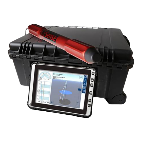
For the purpose of calculating the size of demolition charges, it is important to know the exact position, direction and deviation of the drilled holes. The Robit M Sense system measures the deviation of the hole using a gyroscope and accelerometer inside the measurement probe. The measurement is performed by lowering the measurement probe into the drilled hole and the measurement data is transmitted to a computer when the module is lifted. -
Page 9: Operating Principle
Protective case for system components. Operating principle The Robit Sense measurement software is a versatile tool for measuring boreholes. The measurement data can be saved in a database, where it can be viewed after drilling or at a later time. -
Page 10: User Interface
Link the transferred information to the drilled hole. User interface The user interface of the Robit Sense M system is designed to be used with a touch screen or mouse. The Robit Sense measurement software can be used to design drilling fields, measure drilled holes, and inspect and analyse measurements with a range of powerful graphical view and tools. -
Page 11: Licensing
System description Licensing During startup, the software automatically checks that the current license is valid. The license validity period is displayed at the bottom of the home screen. If a license cannot be acquired automatically, the software prompts you to check the availability of licenses. -
Page 12: Registering A Tablet
System description https:// Your Company Administrator can order the organizational registration code from www.sensesystems.com If the licensing period has expired, an error message is displayed. Contact Robit Plc. for more details. 3.4.1 Registering a tablet If the tablet computer's measurement software asks for a registration code, log into https://www.sensesystems.com... - Page 13 You will see a list of licences. Select an available licence to register the tablet with by clicking the Register Tablet text. If the list does not have an available licence, contact Robit personnel. A window with a registration code will open.
- Page 14 System description Review your licence information on the tablet computer and click Proceed to start using the software. 61 - 003 -...
-
Page 15: Operating Instructions
Starting up the software Procedure Start up the Robit Sense software by tapping the software icon on the tablet computer. Once the software has been activated, enter the measuring cable marking interval in metres or feet (imperial cable). - Page 16 Operating instructions The calibration wizard starts. Familiarize yourself with the movement shown by the animation. Click Start when you are ready to perform the movement for about 30 seconds. Carry through the movement until the animation stops. If the calibration wizard detects insufficient movement, the calibration is rejected. 61 - 003 -...
-
Page 17: Measurement Settings
Operating instructions When calibration is successfully completed, you'll see "Calibrated" message. You can now close the calibration wizard. Measurement settings You can define the measurement settings in the Settings > Measurement settings view. Measuring direction A borehole can be measured either starting from the bottom or from the top. Measurement point interval Measuring cable marking interval in metres or feet (imperial cable). -
Page 18: Measuring View
Operating instructions Measuring mode The measuring mode can be defined under the Compass section: • Gyro only for magnetic conditions. The Operator sets the collar heading for each hole. The Gyro only mode is sensitive to correct working methods. Note: Azimuth information on vertical and horizontal holes is limited. •... - Page 19 Operating instructions Press Begin lifting to start. Enter the borehole length using the slider or the + and - buttons. If the current borehole inclination is known, select Yes and enter the initial angle using the slider or the + and - buttons. Press Record to take the first measurement.
- Page 20 Operating instructions Once the measurement has been marked, the program returns to the measurement view. Note: If the bottom of the hole is not at full meters/feet, the second timestamp is always taken at full meters/feet regardless of the measurement interval. After the second timestamp, the chosen measurement interval applies.
- Page 21 Operating instructions Once the final measurement marking on the measurement cable has been reached, end the measurement by pressing the Finalize measurement button. Note: The final measurement is recorded at the depth defined as nearest surface point in measurement settings. Once the measurement has been done, the results can be saved for the desired field.
-
Page 22: Measuring A Borehole From The Top Down
Operating instructions 4.4.2 Measuring a borehole from the top down Procedure Select Start new measurement to start the measuring process. Lower the measurement probe to the depth defined as the nearest surface point in measurement settings. Press the Record button to record the first measurement. 61 - 003 -... - Page 23 Operating instructions Note: Do not move the measurement probe when the measurement is being recorded. Hold the measurement probe in place until the timer and text on the display disappear. Note: If the measurement probe is shaken during measurement, the timer is reset and an alarm is sounded.
- Page 24 Operating instructions Once the bottom of the borehole has been reached, end the measurement by pressing the Bottom reached button. Enter the borehole length using the slider or the + and - buttons. If the current borehole inclination is known, select Yes and enter the initial angle using the slider or the + and - buttons.
-
Page 25: Measurement Quality View
Operating instructions the selected hole. If a site or position is not indicated for the hole, it is saved without location data. 4.4.3 Measurement quality view After each measurement, the system displays a measurement quality view which helps in spotting and improving accuracy affecting issues. The measurement quality view contains e.g. -
Page 26: Results View
Operating instructions Results view Measured holes can be examined in the inspection view. To access this view, click the Results button in the home menu. You can also view the measurement results by selecting the desired hole in the site view and pressing the Inspect button. -
Page 27: Site View
Operating instructions • Measurement interval • Number of measurement points • Total hole length • Distance from the desired hole position • Hole inclination • Hole Azimuth value. The hole being inspected can be changed by clicking the Menu button at the bottom edge of the view. - Page 28 Operating instructions By tapping the cloud icon, you can see the fields stored in the cloud service but have not been used locally. Select the shape of the new drilling plan. Set the distance of the first drilling row from the edge of the slope. 61 - 003 -...
- Page 29 Operating instructions Set the distance between the first two rows. Set the remaining row intervals. Set the distance between row columns. 61 - 003 -...
-
Page 30: Deleting A Site, Level Or Plan
Operating instructions Set the true bearing of the field by touching and rotating the compass. 4.6.2 Deleting a site, level or plan You can delete a site, level or plan via the Menu button in the lower left corner. Procedure Select the site, level or drilling plan to be deleted. - Page 31 Operating instructions Tap on the trashcan icon the mark the selected item(s) for deletion. Tap on the trashcan icon on the site, level or plan to delete the specific item. Confirm delete by tapping the Yes button or cancel by tapping No. The selected item is deleted.
-
Page 32: Additional Information Dialog
Operating instructions 4.6.3 Additional information dialog You can view additional information about the drilling plan by clicking the ᴠ button at the upper edge of the Site view. You can mark the plan as completed, change the vertical alignment of boreholes and export plan measurements. The system supports different export configurations which define how the data is exported. - Page 33 Operating instructions Figure 2. Measuring settings tab The measuring mode can be defined under the Compass section: • Gyro only for magnetic conditions. The Operator sets the collar heading for each hole. The Gyro only mode is sensitive to correct working methods. Note: Azimuth information on vertical and horizontal holes is limited.
-
Page 34: Inspection And Service
Inspection and service Inspection and service The following inspections must be performed at regular intervals in order to ensure that the measuring system operates as intended. Note: Never use damaged components! 61 - 003 -... -
Page 35: Troubleshooting
Troubleshooting Troubleshooting 61 - 003 -... -
Page 36: Environment And Recycling
Environment and recycling Environment and recycling Disposal of components Do not dispose of electrical and electronic components with other waste. Separate electrical and electronic devices from other waste in order to avoid environmental and health detriments. If you are unfamiliar with the local recycling instructions, please contact the local retailer. -
Page 37: Technical Specifications
Technical specifications Technical specifications Standards The Robit M Sense system components comply with the following industrial standards: • IEC 61000-6-4 Part 6-4: Generic standards - Emission standard for industrial environments • IEC 61000-6-2 Part 6-2: Generic standards - Immunity for industrial environments... - Page 38 This system bears the CE marking. This means that the system and its accessories adhere to the applicable directives, norms and regulations. As proof of compliance with health and safety requirements, Robit Plc supplies an EU/CE certificate with each system sold in the EU/EEC area.
- Page 39 Appendices Appendices 61 - 003 -...
Need help?
Do you have a question about the M Sense and is the answer not in the manual?
Questions and answers