
Subscribe to Our Youtube Channel
Related Manuals for SamplexPower EVO-30AB

Summary of Contents for SamplexPower EVO-30AB
- Page 1 30 Amp Owner's Read this manual before operating Manual Solar Charge your charge Controller controller. EVO-30AB...
-
Page 2: Table Of Contents
4.1 Features ....................16 4.1.1 Standalone Charge Controller ..........17 4.1.2 Expanded Use with Other EVO Products ......17 4.2 EVO-30AB Charging Operation ............18 4.2.1 Pulse Width Modulation ............18 4.2.2 Standard Charging Cycle ............19 4.2.3 Lead Acid Charging ..............20 4.2.4 Equalization Charging Cycle ............21 4.2.5 Temperature Compensation ............24... - Page 3 6.4.1 Manual Equalization ..............37 6.4.2 Automatic Equalization .............37 6.5 Temperature Compensation Operation ..........37 6.6 Expanded Use: Connections & Setup ..........39 6.6.1 Remote Display - EVO-RC-PLUS (Option)........39 6.6.2 EVO-30AB with EVO Inverter/Charger and EVO-RC-PLUS ..............40 6.6.3 EVO-30AB with EVO Inverter/Charger (No EVO-RC-PLUS) ..............41 SECTION 7 7.
- Page 4 Fig 5.1 EVO-30AB Layout ................25 Fig 5.2 EVO-RC-PLUS Layout ................27 Fig 5.3 Startup Screen ..................28 Fig 5.4 EVO-RC-PLUS and EVO-30AB Menu Map ...........31 Fig 6.1 EVO-30AB Dimensions ................33 Fig 6.2 EVO-30AB Wiring Diagram ..............34 Fig 6.3 EVO-30AB with EVO-RC-PLUS Wiring Diagram ........39 Fig 6.4 EVO-30AB with EVO-RC-PLUS and...
-
Page 5: Safety Instructions
SECTION 1 | SAFETY INSTRUCTIONS Read instructions before installing or operating the Charge Controller to prevent per- sonal injury and avoid damage to the Charge Controller. 1.1 Installation and Wiring Compliance • Installation and wiring must comply with the local and National Electrical Codes and must be done by a certified electrician. -
Page 6: Solar Panel Power Theory
SECTION 2 | SOLAR PANEL POWER THEORY 2.1 Solar Panel Ratings and Power Curves Fig. 2.1. Current (I),Voltage (V) and Power (P) Curves A Current (I) versus Voltage (V) Curve of a Solar Panel (“I-V” Curve) shows the possible combinations of its current and Voltage outputs. A typical I-V curve for a 12V Panel is shown in Fig. -
Page 7: Standard Test Conditions (Stc) For Specifying Solar Panels
SECTION 2 | SOLAR PANEL POWER THEORY The rated power of the Solar Panel in Watts (Pmax) is derived from voltage at Vmp multiplied by current at Imp to get the Maximum Power Point (MPP): • Rated power in Watts, Pmax = Vmp X Imp = 2.7A = 2.5A = 17A... -
Page 8: Battery Theory
SECTION 2 | SOLAR PANEL POWER THEORY The output current of the Solar Panel can increase due to what is known as the “Edge of the Cloud Effect”. As the sun moves into a hole between the clouds, your solar panels will see full direct sunlight combined with reflected light from the clouds! They will absorb more energy than they could on a cloudless day! Thus, a factor of 1.25 times the Short Circuit Current Isc is recommended when sizing the current capacity... -
Page 9: Table 3.1 Battery Sizing Formulas
SECTION 3 | BATTERY THEORY For example, backup energy may be required at 10 amps (from the battery at the battery voltage) for 4 hours. This would be 40 AH required from the battery. Determining the size of the battery starts with calculating your requirements in Ah, then adding in factors for efficiency and battery life expectancy. -
Page 10: Series And Parallel Connection Of Batteries
SECTION 3 | BATTERY THEORY Determining Actual Ah Capacity of Battery Bank Lead Acid batteries: In applications where your batteries will be discharged and recharged constantly (cycling), the battery life expectancy will depend on the depth of discharge on the battery. Deep discharges of the battery will significantly reduce the life expectancy. -
Page 11: Series - Parallel Connection
SECTION 3 | BATTERY THEORY common Positive connection becomes the Positive terminal of the 12V bank. Similarly, the four Negative terminals of Batteries 1 to 4 are paralleled (connected together) and this common Negative connection becomes the Negative terminal of the 12V battery bank. -
Page 12: Lead Acid Batteries
SECTION 3 | BATTERY THEORY • The battery with lower series resistance will take shorter time to charge as compared to the battery which sees higher series resistance and hence, will experience over charging and its life will be reduced. •... -
Page 13: Typical Battery Sizes
SECTION 3 | BATTERY THEORY Deep Cycle Lead Acid Batteries Deep cycle batteries are designed with thick-plate electrodes to serve as primary power sources, to have a constant discharge rate, to have the capability to be deeply discharged up to 80% capacity and to repeatedly accept recharging. They are marketed for use in recreation vehicles (RV), boats and electric golf carts –... -
Page 14: Battery Efficiency
SECTION 3 | BATTERY THEORY 100 Ah capacity battery will deliver 100% (i.e. full 100 Ah) capacity if it is slowly discharged over 20 hours at the rate of C/20 A or 5A. However, if it is discharged at a rate of 2 Hrs. (C/2A or 50A) then the Table above shows that for 2 Hours discharge rate (C/2A or 50A), the capacity is reduced to 50% (i.e. -
Page 15: Lithium Batteries
SECTION 3 | BATTERY THEORY In case temperature compensation is not provided, the warmer battery at 40ºC will begin to heat and outgas at 13.95V and will continue to overcharge until the non- compensated Absorption Voltage set point is reached (14.4V). In cooler temperatures, the 10ºC battery will experience severe undercharging, resulting in sulfation. -
Page 16: Effects Of Temperature On Lithium Batteries
Be sure to check with the manufacturer on whether the battery can be placed in series or parallel. Some lithium battery products do not support series configurations. The EVO-30AB is a PWM (Pulse Width Modulation) Solar Charge Controller. It can be used for 12V or 24V battery systems. -
Page 17: Standalone Charge Controller
SECTION 4 | FEATURES & OPERATION 4.1.1 Standalone Charge Controller The EVO-30AB can be installed as a standalone charge controller or it can be added to other EVO products and connected using the communications cable to allow your products to communicate and be monitored from the same remote. -
Page 18: Evo-30Ab Charging Operation
SECTION 4 | FEATURES & OPERATION 4.2 EVO-30AB Charging Operation 4.2.1 Pulse Width Modulation In order to understand the working of the controller, it is important to understand the concept of PWM and Duty Cycle, which are explained with the help of Fig. 4.1. -
Page 19: Standard Charging Cycle
SECTION 4 | FEATURES & OPERATION (modulated) and is defined by “Duty Cycle” which is the ratio of the “ON Time” to the “Pulse Period ”. Duty Cycle is normally specified in %. Thus, 0% Duty Cycle will mean that the switch is constantly OFF (will output 0A) and 100% Duty Cycle will mean that the switch is constantly ON (will output the full Short Circuit Current (I 4.2.2 Standard Charging Cycle Notes:... -
Page 20: Lead Acid Charging
FEATURES & OPERATION Transition from one stage to the other will be controlled by the selected Voltage Regulation Set Points programmed on the EVO-30AB via the DIP switches or from an Inverter/Charger as follows: • Absorption Voltage Regulation Set Point “Va”... -
Page 21: Equalization Charging Cycle
SECTION 4 | FEATURES & OPERATION Float Stage will NOT take place (the periods during which the battery voltage falls below “Va” are not counted towards 1 hour time period). During Absorption Stage, if the load current is more than the current from the solar panel, the battery voltage will drop. - Page 22 SECTION 4 | FEATURES & OPERATION Stage - 1: Bulk Stage. Refer to Fig 4.2B. During the night of the 27th day, the battery voltage will drop below the Float Transition Voltage Set Point “Vf” (Curve portion A1 to B1), as there is no sun and discharging takes place due to loads that are powered during the night e.g.
- Page 23 SECTION 4 | FEATURES & OPERATION panel Status LED will still be blinking Orange. It will revert to PWM when the battery voltage reaches Equalization Transition Voltage Set Point “Ve” and is sustained for a minimum period of around 50 to 55 sec. WARNING! Once Equalization Stage is activated, it will not exit this Stage unless the there is adequate charging current from the solar panel to charge the battery...
-
Page 24: Temperature Compensation
SECTION 4 | FEATURES & OPERATION is switched ON but is switched OFF before completion, the charger reverts to “Bulk Stage” and undergoes Standard Charging Cycle explained in Section 4.2.2. 4.2.5 Temperature Compensation The temperature of the battery electrolyte affects the rate of chemical reactions in the batteries as well as the rate of diffusion and the resistivity of the electrolyte. -
Page 25: Construction, Layout & Controls
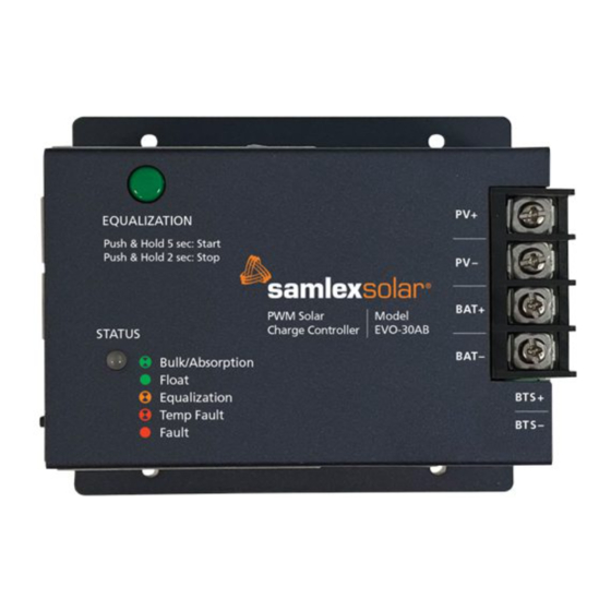
CONSTRUCTION, LAYOUT & CONTROLS 5.1 General The EVO-30AB is designed for surface mounting. All the electronics, DIP switches for settings, terminal strip for connections of the Solar Array, Battery, Battery Temperature Sensor, and communications ports are accessible without the need for opening the cover. -
Page 26: Table 5.1 Led Display For Charging Stages & Faults
Temperature > 90°C > 90°C Fault Condition Table 5.1. LED Display for Charging Stages & Faults The EVO-30AB has the following controls to manage functions of the unit while operating as a standalone charge controller. BUTTONS ACTION Reset AH Push and hold to zero the Amp-Hours on optional EVO-RC-PLUS Display. -
Page 27: Evo-Rc-Plus Remote Display Operation
The level of brightness / dimming of the LCD backlight can be programmed to suit user preference. On/Off Key (2) – This button has no function for the EVO-30AB. The On/Off Key is used for powering ON and OFF the EVO Inverter/Charger. -
Page 28: Evo-Rc-Plus Display Screens
Navigation Keys (5,6,7,8) – these four keys allow simple access to Menu Items that assist in monitoring and troubleshooting the EVO-30AB. • Back – no effect when EVO-30AB is in the only device connected. Otherwise, use to move from main EVO Inverter/Charger Screen to EVO-30AB screen when Inverter/Charger is connected. -
Page 29: Table 5.3 Operational Screens
CONSTRUCTION, LAYOUT & CONTROLS Operational Screens • With an EVO Inverter/Charger installed: Press the Back key to see the EVO-30AB screen. • Without an EVO Inverter/Charger installed: The EVO-30AB screen is shown automatically. Press UP/DOWN Keys to navigate between screens. -
Page 30: Table 5.4 Lcd Display Parameters
Table 5.4: LCD Display Parameters To access the parameters menu, from any of the Operational Screen, press ENTER. If only the EVO-30AB is connected to the EVO-RC-PLUS then the menu map shown in Figure 5.4 is applicable. If other equipment is connected to the EVO-RC-PLUS (such as an inverter/charger) please refer to the EVO-RC-PLUS manual Section 4.2.2 for further details. - Page 31 S T O P C A R S T O P C A R 0 = N o Figure 5.4: EVO-RC-PLUS and EVO-30AB Menu Map To Modify and Save the Parameter: • To change a cell: Use the UP / DOWN buttons •...
-
Page 32: Installation & Setup
SECTION 6 | INSTALLATION & SETUP This section provides instructions on how to install and setup the EVO-30AB charge controller. WARNING! ENSURE the battery + and - wires are correctly connected before proceeding. • • Damage due to reverse battery connection is not covered under warranty! •... -
Page 33: Selecting A Location And Mounting
EVO-30AB CHARGE CONTROLLER 20427-EVO-30AB-0421 20427-EVO-30AB-0421 6.2 Selecting a Location and Mounting Mount the EVO-30AB in a location that is free from moisture and dirt. SIDE A SIDE A The location should meet the temperature operating requirements and the unit should be placed in a space that allows good circulation of air for heat dissipation. -
Page 34: Connections And Setup
Battery Temperature Sensor Fig. 6.2. EVO-30AB Wiring Diagram 1. The connections to the EVO-30AB terminals are shown in the drawing in Fig. 6.2. A barrier type of Terminal Strip has been provided for connecting the PV array and the battery. M-4 screws with clamping washers are used to make the connection. -
Page 35: Dip Switch Settings
*Factory preset condition Table 6.2. Dip Switch Settings Standard Battery Charging Programs EVO-30AB provides 8 standard battery charging algorithms (programs) that are selected with DIP Switches 2, 3, 4. Table 6.3 below summarizes the major parameters of the standard charging algorithms. -
Page 36: Equalization Operation
6.4 Equalization Operation When Equalization is activated, the following indications will be seen on the EVO-30AB unit: • Status LED will blink Orange, once per second • Once the battery is overcharged and its voltage rises to the Equalization Voltage Regulation Set Point and is sustained at this level for the programmed period, the charger will revert to Float Stage –... -
Page 37: Manual Equalization
INSTALLATION & SETUP WARNING! DIP Switch Settings for Failed Communications The DIP switch on the EVO-30AB charge controller should be programmed in case the communications cable becomes disconnected to the EVO Inverter/Charger. The EVO-30AB will revert to the DIP switch settings if this happens. -
Page 38: Table 6.4 Temperature Compensation Of Voltage Settings
SECTION 6 | INSTALLATION & SETUP Typical compensation is given in Table 6.4 below: VOLTAGE COMPENSATION BATTERY ELECTROLYTE TEMPERATURE 12V BATTERY 24V BATTERY 50ºC / 122ºF – 0.75V –1.50V 45ºC / 113ºF – 0.60V – 1.20V 40ºC / 104ºF – 0.45V –... -
Page 39: Remote Display - Evo-Rc-Plus (Option)
SECTION 6 | INSTALLATION & SETUP 6.6 Connections & Setup with EVO Products Refer to Section 4 for a description of features and benefits when using the EVO-30AB in the following configurations. • With Remote Display • With an EVO Inverter/Charger and a Remote Display •... -
Page 40: Evo-30Ab With Evo
Installing the EVO-30AB Charge Controller, an EVO-RC-PLUS, and an EVO Inverter/ Charger makes your complete power system manageable from one monitoring device. The EVO-RC-PLUS will display alarms and status for both the EVO-30AB and the EVO Inverter/Charger. Install and turn on the EVO Inverter/Charger in accordance with the EVO manual. -
Page 41: Evo-30Ab With Evo
When the EVO-30AB is installed with an EVO Inverter/Charger without the EVO-RC- PLUS, the EVO-30AB will operate based on the DIP switch settings only. The inverter/ charger will manage its charge current based on the output current of the EVO-30AB, as described in the EVO manual (Section 5.4). -
Page 42: Troubleshooting
SECTION 7 | TROUBLESHOOTING 7.1 Fault Indicators Troubleshooting the EVO-30AB controller is simplified with the use of the optional EVO-RC-PLUS display. Some basic troubleshooting procedures are listed below. EVO-30AB EVO-RC-PLUS FAULT (Optional Display) DESCRIPTION CAUSE OF FAULT / REMEDY !!Over Current... -
Page 43: Symptom 1. Battery Is Not Charging
If it is unable to maintain its voltage, the battery may be failing. Measure the PV Voltage and the Battery Voltage at the EVO-30AB terminals. If the voltage at the terminals is the same (within a few tenths of V) the PV array is charging the battery. -
Page 44: Specifications
SECTION 8 | SPECIFICATIONS MODEL NO. EVO-30AB INPUT MAX. OPEN CIRCUIT VOLTAGE (V OF SOLAR PANEL / ARRAY MAX. SHORT CIRCUIT CURRENT (I OF SOLAR PANEL / ARRAY TOTAL SELF CONSUMPTION CURRENT 50 mA OUTPUT / CHARGING TYPE OF CONTROLLER... -
Page 45: Warranty
Warranty 5 YEAR LIMITED WARRANTY EVO-30AB manufactured by Samlex America, Inc. (the “Warrantor“) is warranted to be free from defects in workmanship and materials under normal use and service. The war- ranty period is 5 years for the United States and Canada, and is in effect from the date of purchase by the user (the “Purchaser“). - Page 46 Notes 46 | SAMLEX AMERICA INC.
- Page 47 Notes SAMLEX AMERICA INC. | 47...
- Page 48 Ph: 1 800 561 5885 Fax: 1 888 814 5210 Local Numbers Ph: 604 525 3836 Fax: 604 525 5221 Website www.samlexamerica.com USA Shipping Warehouses Kent, WA Plymouth, MI Canadian Shipping Warehouse Richmond, BC Email purchase orders to orders@samlexamerica.com 11027-EVO-30AB-1122...
- Page 49 Contrôleur Guide Lisez ce manuel avant d’utiliser d’Utilisation de Charge votre charge Solaire de manette. 30 Ampère EVO-30AB...
- Page 50 4.1 Caractéristiques ..............17 4.1.1 Contrôleur de charge autonome .........18 4.1.2 Utilisation étendue avec d’autres produits EVO ..18 4.2 Opération de charge EVO-30AB ..........19 4.2.1 Modulation de largeur d’impulsion ......19 4.2.2 Cycle de charge standard ..........20 4.2.3 Charge d’acide de plomb ..........21 4.2.4 Cycle de charge d’égalisation ..........
- Page 51 6.5 Fonctionnement de la compensation de température ...39 6.6 Utilisation étendue: Utilisation étendue : connexions et configuration ..........41 6.6.1 Affichage à distance - EVO-RC-PLUS (En option) ..41 6.6.2 EVO-30AB avec onduleur / chargeur EVO EVO-RC-PLUS ..............42 6.6.3 EVO-30AB avec convertisseur / chargeur EVO (pas de EVO-RC-PLUS) ..........43 SECTION 7 7.
- Page 52 Fig 5.1 Disposition EVO-30AB ............27 Fig 5.2 Disposition de l’EVO-RC-PLUS ..........29 Fig 5.3 Écran de démarrage ..............30 Fig 5.4 Carte des menus EVO-RC-PLUS et EVO-30AB .......33 Fig 6.1 Dimensions de l’EVO-30AB ...........35 Fig 6.2 Schéma de câblage EVO-30AB..........36 Fig 6.3 EVO-30AB avec schéma de câblage EVO-RC-PLUS ....41 Fig 6.4 Schéma de câblage de l’onduleur/chargeur...
-
Page 53: Les Consignes De Sécurité
SECTION 1 | LES CONSIGNES DE SÉCURITÉ Lisez les instructions avant d’installer ou d’utiliser le contrôleur de charge pour éviter les blessures et éviter d’endommager le contrôleur de charge. 1.1 La Conformité de l’Installation et du câblage • L’installation et le câblage doivent être conformes aux codes locaux et au National Electric Code (NEC);... -
Page 54: Théorie De La Puissance Des Panneau Solaire
SECTION 2 | THÉORIE DE LA PUISSANCE DES PANNEAU SOLAIRE 2.1 Puissances nominales et courbes de puissance La Fig. 2.1. Courbes de Courant (I), Tension (V) et Puissance (P) Une courbe de Courant (I) versus la Tension (V) d’un Panneau Solaire (la Courbe « I-V ») montre les combinaisons possibles de sorties de courant et de Tension. -
Page 55: Conditions D'essai Standard (Stc) Pour La Spécification Des Panneaux Solaires
SECTION 2 | THÉORIE DE LA PUISSANCE DES PANNEAU SOLAIRE La puissance nominale du panneau solaire en watts (Pmax) est dérivée de la tension à Vmp multipliée par le courant à Imp pour obtenir le point de puissance maximale (MPP) : •... -
Page 56: Théorie De La Batterie
SECTION 2 | THÉORIE DE LA PUISSANCE DES PANNEAU SOLAIRE 2.4 Facteurs affectant la production des cellules solaires La quantité de courant électrique générée par l’excitation photonique dans une cellule solaire à une température donnée est affectée par la lumière de deux manières : •... -
Page 57: Dimensionnement Du Banc De Batteries
SECTION 3 | THÉORIE DE LA BATTERIE Dans ce cas, la capacité de 100 Ah est évaluée à un taux de décharge de 20 heures jusqu’à ce que la tension chute à 175 V par cellule (ou 10,5 V sur une batterie de 12 V). La capacité... -
Page 58: La Connexion En Série Et En Parallèle Des Batteries
SECTION 3 | THÉORIE DE LA BATTERIE b) Déterminer / calculer la puissance en watts évidé de la batterie in Watts (W) par les dispositifs CA et CC. Pour les dispositifs CC, ceci serait pareil que la puissance nominale CC (Formule 3). Pour les dispositifs CA alimentés par un onduleur CC à CA, utilisez la Formule 4 pour calculer la puissance en Watts (W) évidée de la batterie. -
Page 59: La Connexion En Parallèle
SECTION 3 | THÉORIE DE LA BATTERIE 3.2.2 La Connexion en Parallèle Cable “A” Batterie 1 Batterie 2 Batterie 3 Batterie 4 PV + PV - BAT + Batterie Batterie Batterie Batterie BAT - de 12V de 12V de 12V de 12V Régulateur de charge solaire Cable “B”... -
Page 60: Batteries Au Plomb
SECTION 3 | THÉORIE DE LA BATTERIE la batterie de la première batterie (batterie 1 dans la Fig. 3.2) ou à la borne positive de la batterie de la première chaîne de batterie (batterie 1 de la chaîne 1 sur la figure 3.3), le câble de sortie négatif du chargeur de batterie (câble « B ») doit être connecté... - Page 61 SECTION 3 | THÉORIE DE LA BATTERIE hydromètre. Quand pleinement chargée, la cellule a une tension approximative de 2,105V et l’électrolyte une densité de 1,265. Pendant le déchargement, la tension et la densité baisse. Donc, une batterie de 12v nominale saine et pleinement chargée avec 6 cellules pleinement chargée à...
-
Page 62: Les Tailles De Batterie Typiques
SECTION 3 | THÉORIE DE LA BATTERIE 3.3.2 Les Tailles de Batterie Typiques Le Tableau ci-dessous montre les spécification de quelques batteries populaires: GROUPE BCI* TENSION DE BATTERIE, V CAPACITÉ TYPIQUE, AH 27 / 31 GC2** * Conseil de Batterie Internationale ** Voiturette de Golf Le Tableau 3.2. -
Page 63: Impact De La Profondeur De Décharge Sur La Durée De Vie De La Batterie
SECTION 3 | THÉORIE DE LA BATTERIE 3.3.5 Impact de la profondeur de décharge sur la durée de vie de la batterie Plus une batterie est déchargée à chaque cycle, plus la durée de vie de la batterie est courte. Utilisant plus de batteries que le minimum exigé va allonger la vie de la banque de batterie. -
Page 64: Piles Au Lithium
SECTION 3 | THÉORIE DE LA BATTERIE Il est recommandé que chargeur de batterie / contrôleur de charge avec une fonctionne pour détecter et compenser la température si l’électrolyte de batterie varie par plus que 5ºC à 10ºC (9ºF à 18ºF). Perte de la Capacité... -
Page 65: Effets De La Température Sur Les Batteries Au Lithium
SECTION 4 | CARACTÉRISTIQUES ET FONCTIONNEMENT L’EVO-30AB est un contrôleur de charge solaire PWM (Pulse Width Modulation). Il peut être utilisé pour les systèmes de batterie 12V ou 24V. 4.1 Caractéristiques • La fonctionnalité s’étend lorsqu’elle est connectée à un affichage à distance EVO ou à... -
Page 66: Contrôleur De Charge Autonome
CARACTÉRISTIQUES ET FONCTIONNEMENT 4.1.1 Contrôleur de charge autonome L’EVO-30AB peut être installé en tant que contrôleur de charge autonome ou il peut être ajouté à d’autres produits EVO et connecté à l’aide du câble de communication pour permettre à vos produits EVO de communiquer et d’être surveillés à... -
Page 67: Opération De Charge Evo-30Ab
CARACTÉRISTIQUES ET FONCTIONNEMENT 4.2 Opération de charge EVO-30AB La conception et le fonctionnement de l’EVO-30AB sont basés sur un contrôle de type série PWM (modulation de largeur d’impulsion) à une fréquence de 300 Hz. 4.2.1 Modulation de largeur d’impulsion Afin de comprendre le fonctionnement du contrôleur, il est important de comprendre le concept de PWM et Duty Cycle, qui sont expliqués à... -
Page 68: Cycle De Charge Standard
SECTION 4 | CARACTÉRISTIQUES ET FONCTIONNEMENT commutation par seconde est appelé la fréquence PWM. Mathématiquement, Fréquence = (1 Période d’impulsion « T ») et est de 300 Hz dans ce cas (1 33,3 ms = 300 Hz). La durée de l’état ON est également appelée « Largeur d’impulsion ». Dans le contrôle PWM, la durée de la largeur d’impulsion est variée (modulée) et est définie par le « cycle de service »... -
Page 69: Charge D'acide De Plomb
Étape 3: Étape flottante - Charge à tension constante. La transition d’une étape à l’autre sera contrôlée par les points de consigne de régulation de tension sélectionnés programmés sur l’EVO-30AB via les commutateurs DIP ou à partir d’un onduleur/chargeur EVOTM comme suit : •... - Page 70 SECTION 4 | CARACTÉRISTIQUES ET FONCTIONNEMENT de Chargement Constante. C’est une condition de surtension contrôlée intentionnelle pour la batterie pendant 1 Hr. Ceci est nécessaire pour retourner la 205 de la capacité restante. À cette tension, la batterie commence la gazéification (évolution de l’Hydrogène et l’Oxygène à...
-
Page 71: Cycle De Charge D'égalisation
SECTION 4 | CARACTÉRISTIQUES ET FONCTIONNEMENT 4.2.4 Cycle de charge d’égalisation ATTENTION! • L’égalisation est effectuée uniquement pour les batteries au plomb-acide à cellules non-scellées / à plomb ouvert / inondées /mouillées. • N’égalisez pas les batteries scellées Lithium / VRLA de type AGM / Gel Cell, sauf autorisation du fabricant de la batterie. - Page 72 SECTION 4 | CARACTÉRISTIQUES ET FONCTIONNEMENT est maintenue pendant une période minimale d’environ 50 à 55 s. Cette étape est chronométrée pour une période continue / cumulative de 1/2/3 heures en fonction du type de batterie programmé. Pendant la période d’égalisation (partie de courbe C1 à D1), la batterie est en condition de surcharge, dégage et bouillonne vigoureusement et l’électrolyte est agité, ce qui entraîne l’élimination de la stratification.
-
Page 73: La Compensation De Température
SECTION 4 | CARACTÉRISTIQUES ET FONCTIONNEMENT • il devrait avoir une pleine exposition à la lumière solaire pour un jour (aucune ombre ni nuages) Étape- 3: Étape de Maintien. Le contrôleur entre cet étape de l’étape d’égalisation précédent au point « D1 » après que la tension de batterie est gardée au point de réglage de tension d’absorption «... -
Page 74: Chargement De La Batterie Au Lithium
SECTION 4 | CARACTÉRISTIQUES ET FONCTIONNEMENT Tous les point de réglages de tension de chargement sont normalement spécifié à 25ºC / 77ºF. Dans un système PV, les température de batterie varient de jusqu’à 15ºC du point de référence de 25ºC. Les Tensions d’Absorption, Maintien & Égalisation devrait être ajusté, ou un contrôleur avec un Capteur Thermique doit être utilisé. -
Page 75: Construction, Aménagement & Contrle
& CONTRLE 5.1 Générale L’EVO-30AB est conçu pour un montage en surface. Toute l’électronique, les commutateurs DIP pour les réglages, le bornier pour les connexions du panneau solaire, la batterie, le capteur de température de la batterie et les ports de communication sont accessibles sans qu’il soit nécessaire d’ouvrir le couvercle. -
Page 76: Commandes Et Indicateurs
> 90°C >90°C Tableau 5.1. Affichage LED pour les étapes de charge et les défauts L’EVO-30AB dispose des commandes suivantes pour gérer les fonctions de l’unité tout en fonctionnant comme un contrôleur de charge autonome. BOUTONS ACTION Appuyez et maintenez enfoncé pour mettre à zéro les ampères-heures sur Réinitialiser AH... -
Page 77: Fonctionnement De L'affichage À Distance Evo-Rc-Plus
Le niveau de luminosité / gradation du rétroéclairage LCD peut être programmé en fonction des préférences de l’utilisateur. Touche Marche/Arrêt (2) – Ce bouton n’a aucune fonction pour l’EVO-30AB. La touche Marche/Arrêt est utilisée pour allumer et éteindre l’onduleur/chargeur EVO . -
Page 78: Écrans D'affichage De L'evo-Rc-Plus
1 . 0 6 I D = Figure 5.3 : écran de démarrage Le contrôleur indiquera « EVO-30AB » sur la deuxième ligne et établira une connexion. VER : Indique la version du micrologiciel de l’EVO-30AB. 30 | SAMLEX AMERICA INC. -
Page 79: Tableau 5.3 Écrans Opérationnels
: Appuyez sur la touche Retour pour voir l’écran EVO-30AB. • Sans onduleur/chargeur EVO installé : L’écran EVO-30AB s’affiche automatiquement. Appuyez sur les touches HAUT/BAS pour naviguer entre les écrans. Affiche la tension de la batterie, le cou- E V O - 3 0 A B rant du chargeur. -
Page 80: Tableau 5.4 Paramètres D'affichage Lcd
Tableau 5.4 : Paramètres de l’écran LCD To access the parameters menu, from any of the Operational Screen, press ENTER. Si seul l’EVO-30AB est connecté à l’EVO-RC-PLUS, la carte des menus illustrée à la Figure 5.4 s’applique. Si un autre équipement est connecté à l’EVO-RC-PLUS (tel qu’un onduleur/chargeur), veuillez vous reporter à... -
Page 81: Fig 5.4 Carte Des Menus Evo-Rc-Plus Et Evo-30Ab
C A R S T O P C A R 0 = N o Figure 5.4 : Carte des menus EVO-RC-PLUS et EVO-30AB Pour modifier et enregistrer le paramètre : • Pour changer de cellule : Utilisez les boutons UP / DOWN •... -
Page 82: Installation Et Configuration
15 A et la distance de fonctionnement est de 12 pieds, utilisez AWG # 10. • EVO-30AB empêche les fuites de courant inverse la nuit via un commutateur MOSFET interne, de sorte qu’une diode de blocage externe n’est pas requise dans le système. -
Page 83: Sélection D'un Emplacement Et D'un Montage
EVO-30AB est conçu pour réguler la puissance d’un générateur photovoltaïque. D’autres 20427-EVO-30AB-0421 20427-EVO-30AB-0421 chargeurs peuvent être connectés directement à la batterie sans effet sur l’EVO-30AB. 6.2 Sélection d’un emplacement et d’un montage Montez l’EVO-30AB dans un endroit exempt d’humidité et de saleté. -
Page 84: Connexions Et Configuration
Batterie La Fig. 6.2 Schéma de câblage EVO-30AB 1. Les connexions aux bornes EVO-30AB sont illustrées sur le schéma de la Fig. 6.2. Un bornier de type barrière a été fourni pour connecter le générateur photovoltaïque et la batterie. Des vis M-4 avec rondelles de serrage sont utilisées pour réaliser la connexion. -
Page 85: Reglages Des Interrupteurs Dip
Tableau 6.2. Paramètres des commutateurs DIP Programmes de Chargement de Batterie Standards Le EVO-30AB a 8 algorithmes de chargement de batterie standards (programmes) qui peuvent être sélectionnés grâce aux interrupteurs DIP 2,3,4. Le Tableau 6.3. ci-dessous présente les paramètres principaux des algorithmes de chargement standards. -
Page 86: Tableau 6.3 Programmes De Charge De Batterie Standard
SECTION 6 | INSTALLATION ET CONFIGURATION AVIS: Toutes les valeurs indiquées sont pour une température de Toutes les valeurs de Tension sont à une température de 25°C (77°F) 25ºC (77ºF). Toutes les tensions dans le Tableau sont pour des systèmes de 12 V. Pour des systèmes de 24 V, multipliez les tensions par 2. -
Page 87: Opération D'égalisation
MISE EN GARDE Paramètres des commutateurs DIP pour les communications échouées Le commutateur DIP du contrôleur de charge EVO-30AB doit être programmé au cas où le câble de communication serait déconnecté de l’onduleur/chargeur EVO L’EVO-30AB reviendra aux paramètres du commutateur DIP si cela se produit. - Page 88 SECTION 6 | INSTALLATION ET CONFIGURATION Les profils 7 et 8 pour le lithium ont cette fonction désactivée, mais le capteur peut toujours être utilisé pour surveiller la température. ATTENTION! Le câblage du Capteur Thermique de Batterie est polarisé, donc il est marqué...
-
Page 89: Affichage À Distance - Evo-Rc-Plus (En Option)
1. Réglez le commutateur DIP sur l’EVO-30AB. Les paramètres sont fournis sur l’appareil ou se trouvent dans la section 4. 2. Installez l’EVO-30AB comme décrit dans les sections 6.1 à 6.3 de ce manuel. 3. Installez l’EVO-RC-PLUS conformément au manuel EVO-RC-PLUS. -
Page 90: Evo-30Ab Avec Onduleur / Chargeur Evo
Réglez le commutateur * DIP sur l’EVO-30AB. Les paramètres sont fournis sur l’appareil ou se trouvent dans la section 4. Installez l’EVO-30AB comme décrit dans les sections 6.1 à 6.3 de ce manuel, mais en effectuant la connexion de la batterie à la «connexion du chargeur CC externe sur l’onduleur / chargeur EVO... -
Page 91: Evo-30Ab Avec Convertisseur / Chargeur Evo
Réglez le commutateur * DIP sur l’EVO-30AB. Les paramètres sont fournis sur l’appareil ou se trouvent dans la section 4. Installez l’EVO-30AB comme décrit dans les sections 6.1 à 6.3 de ce manuel, mais en effectuant la connexion de la batterie à la «connexion du chargeur CC externe sur l’onduleur / chargeur EVO... -
Page 92: Dépannage
SECTION 7 | DÉPANNAGE 7.1 Indicateurs de défaut Le dépannage du contrôleur EVO-30AB est simplifié grâce à l’utilisation de l’écran EVO-RC-PLUS en option. Quelques procédures de dépannages sont écrites ci-dessous. LED DE EVO-RC-PLUS DÉFAUT (En option) EVO-30AB DESCRIPTION CAUSE DU DÉFAUT / REMÈDE... - Page 93 Si la batterie ne peut pas maintenir sa tension, elle est peut être défectueuse. Mesurez la tension PV et de la batterie aux bornes du EVO-30AB . Si la tension aux bornes est pareille (à quelques dixièmes de volts près), le système PV recharge la batterie.
- Page 94 SECTION 8 | SPECIFICATIONS MODÈLE EVO-30A ENTREE TENSION EN CIRCUIT OUVERT MAX. (VCC) DU GÉNÉRATEUR / PANNEAU SOLAIRE COURANT DE COURT CIRCUIT MAX. (I ) OF SOLAR PANEL / ARRAY COURANT D’AUTO-CONSOMMATION TOTAL 50 mA SORTIE / CHARGEMENT Série, la Modulation de la Largeurs TYPE DE CONTRÔLEUR d’Impulsions (MLI) TENSION DE SYSTÉME DE BATTERIE NOMINALE BATTERY 12V / 24V (Sélectionné...
- Page 95 Garantie GARANTIE LIMITÉE DE 5 ANS EVO-30AB, fabriqués par Samlex America, Inc. (le « Garant ») sont garantis être non défec- tueux dans la conception et dans les matériaux, moyennant une utilisation et un service normaux. La période de garantie est de 5 ans pour les Etats-Unis et le Canada, et prend effet le jour de l’achat par l’utilisateur («...
- Page 96 Information Contact Numéros Sans Frais Tél: 1 800 561 5885 Téléc: 1 888 814 5210 Numéros locaux Tél: 604 525 3836 Téléc: 604 525 5221 Site internet www.samlexamerica.com Entrepôts USA Kent, WA Plymouth, MI Entrepôt Canada Richmond, BC Adresse email pour passer commande orders@samlexamerica.com 11027-SCC-30AB-1122-FR...
Need help?
Do you have a question about the EVO-30AB and is the answer not in the manual?
Questions and answers