Table of Contents
Advertisement
Advertisement
Table of Contents

Summary of Contents for Ikegami BSX-100
- Page 1 RoHS-compliant Product BSX-100 Base Station OPERATION MANUAL...
- Page 3 OUTLINE RoHS-compliant Product NAME and FUNCTION FORMATS and GENLOCK BSX-100 EQUIPMENT Base Station CONNECTIONS OPERATION MANUAL BS SETTINGS and ADJUSTMENT TROUBLESHOOTING and MAINTENANCE SPECIFICATIONS CHANGING INFORMATION 2012 1st Edition (U) (E)
- Page 4 Copyright © 2020 Ikegami Tsushinki Co., Ltd. Copyright © 2020 Ikegami Tsushinki Co., Ltd. We reserve the copyright on the software we create. We reserve the copyright on the software we create. gami Tsushinki Co., Ltd. gami Tsushinki Co., Ltd.
-
Page 5: Rohs-Compliant Products
- If the wiring of the main unit or the circuit board is polluted with lead solder by the user, repair of the product will not be covered under the warranty as it is impossible to remove the polluted solder. 3. Parts Be sure to use parts that comply with the RoHS directive. BSX-100 2012 VER1 (U) (E) -
Page 6: Information To Users
4. We carried out a test in accordance with EN55103-1 Annex B. As a result, the value of the inrush current is as follows. Inrush current BSX-100 + HDK-79GX + FA-97 + COP-399 : 7.42A 5. Use shielded cable except AC cable. -
Page 7: Safety Precautions
Mishandling may not directly lead to death, injury, or property damage. Indicates that mishandling may cause an electric shock. Indicates that mishandling may cause injury. The following symbol is used to indicate other precautions to prevent damage or hazard from occurring: Indicates a prohibited action. BSX-100 2012 VER1 (U) (E) - Page 8 Do not pour or spill water or other liquid over the equipment. Do not subject the equipment to a strong impact shock or vibration. Doing so may cause damage to or malfunction of the equipment. Excessive sound pressure from the headset may result in hearing impairments. BSX-100 2012 VER1 (U) (E)
- Page 9 (once every three years or 8000 hours of use) is recommended to enable safe use of this product for a long time. Please contact our sales and service centers or Techno Ikegami Co., Ltd. for queries on the regular maintenance and repair of our products.
-
Page 10: How To Read The Operation Manual
HOW TO READ THE OPERATION MANUAL HOW TO READ THE OPERATION MANUAL This page explains the points to note when reading the BSX-100 Operation Manual, as well as the symbols and notations used in the manual. Notes on the Manual ■... - Page 11 ■ This manual is intended for both safe and smooth opertion of the BSX-100. It is made up of six chapters. Reading through the chapters in sequence helps you to smoothly perform the series of steps from installation to operation.
-
Page 12: Table Of Contents
Fuse Replacement ....42 BSX-100 Front View with Front Cover Off . . 3 Front Right ......4 Chapter 7 SPECIFICATIONS Rear . -
Page 13: Chapter 1 Outline
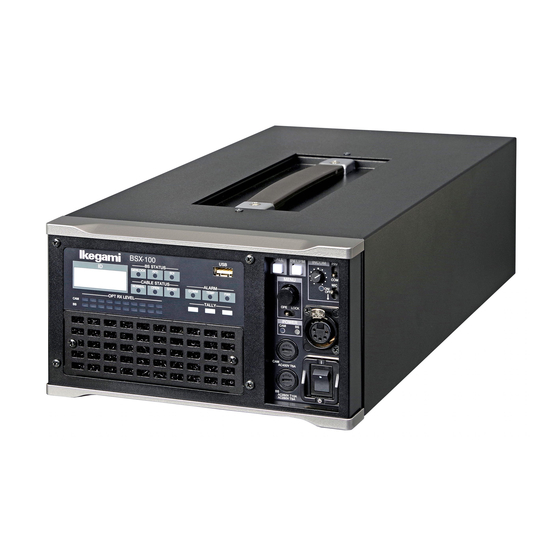
4-channel input function is possible by changing the selection in the BS Menu. Equipped with a video circuit that supports 3Gbps transmission and the 3G-SDI format, the BSX-100 is half-rack size base ■ ICCP & Ethernet station that can be used with the 3G-compatible "Unicam HD"... -
Page 14: Chapter 2 Names And Functions
There is a problem with the with dust. reception of signals transmitted. *2: When the FAN alarm lights up stop the operation Cleaning of the optical composite 1/10 Red Light On cable is required. Alternatively, broken. BSX-100 2012 VER1 (U) (E) -
Page 15: Front View With Front Cover Off
2.1 Front Left / 2.2 BSX-100 Front View with Front Cover Off ⑥ TALLY Indicator Indicators for Red TALLY, Green TALLY, and Yellow TALLY. Lights up when the R/G/Y TALLY signal is input to the TALLY IN connector on the rear of the BS. -
Page 16: Front Right
Every time the switch is pressed, the When it is ON, the LED of the indicator lights PRV/COM : Switches the INTERCOM conversation mode. PRV = Conversation with the camera only. COMM = Conversation with the entire system. BSX-100 2012 VER1 (U) (E) -
Page 17: Rear
For selecting the AES OUT or SYNC OUT format in the BS menu. : Outputs the audio signal that is input to the MIC- 1,2 (AUDIO IN) connectors of the camera. The signal conforms to the AES/EBU format. BSX-100 2012 VER1 (U) (E) -
Page 18: Chapter 3 Formats And Genlock
1080i59.94, and the 1080PsF25 signals as 1080i50, this method is increasingly used in recent years for creating a time-lapse 1080p23.98PD signals are processed as 1080i59.94 signals. 1 frame 1 frame 10 fields (A: odd field, B: even field) BSX-100 2012 VER1 (U) (E) -
Page 19: Genlock System
720P50 ■ S ynchronization Signal Input (REFERENCE) Connector Connection Example (Loop-Through) For input of reference synchronization signals to the REFERENCE connector. When using an external synchronization signal generator BSX-100 SYNC OUT External synchronization signal generator BSX-100 BSX-100 75Ω termination BSX-100 2012 VER1 (U) (E) - Page 20 R E F A CCU or BS #2 B S Y N C O U T R E F Signal generator 7 5 Ω termination CCU or BS #3 Requirement on signals output by the signal generator A: NTSC BBS + 10 FIELD ID (SMPTE 318M-compliant) BSX-100 2012 VER1 (U) (E)
-
Page 21: Chapter 4 Equipment Connections
Please make sure that the power switch is set to "OFF" before connecting this product (camera, BS) and other peripheral equipment. Headset BS (Front View) MAIN POWER Switch Camera (Right View) * The HDK-99 camera head is used in this example for explanation. ACTIVE STANDBY BS/CCU POWER Switch POWER BSX-100 2012 VER1 (U) (E) -
Page 22: Power Supply
[CAM PWR switch] on the OCP for approximately 2 seconds. Power outlet To switch the status of power supply to the camera from OFF (switch light goes off) to ON, press [CAM PWR switch] on the OCP. OCP-300 CAM POWER Switch BSX-100 2012 VER1 (U) (E) - Page 23 Set the POWER switch on the right side of the camera to the OFF side. Connect the connector from the external power supply to the DC IN connector on the rear side of BS/CCU the camera. POWER BSX-100 2012 VER1 (U) (E)
-
Page 24: Bs And Camera Head Connection
Optical fiber composite camera cable 4.4 System Setup Diagram MIC-1 MIC-2 Headset (ENG/PROD) HDK-99 Headset Fiber Cable (ENG/PROD) Max. 2000m *1 BSX-100 3G/HD-SDI 3G/HD-SDI C P Cable *1 Varies depending on the type M a x . 3 0 0 m *2 of lens used and the system configuration. *2 When power is supplied to the OCP from another source. OCP-300 BSX-100 2012 VER1 (U) (E) -
Page 25: External Connections
CONTROL (C) Control signal (C) Camera --> CCU/BS ○ POWER (H) Power (H) supplied to the camera ○ POWER (C) Power (C) supplied to the camera ■ AUDIO OUT Connector ― Male receptacle ― ― Female receptacle ― Insertion Side Insertion Side BS side : HA16RD-3P (76) BS side : HA16RD-3P (71) Cable side : SMP-03V-NC (3-pin female plug) or equivalent Cable side : SMR-03V-N (3-pin male plug) or equivalent Pin No. Name Function External Interface ○ SHIELD AUDIO LINE SHIELD ○ MIC (H) AUDIO LINE HOT ○ MIC (C) AUDIO LINE COLD BSX-100 2012 VER1 (U) (E) - Page 26 PROD B-S(H) PROD CH Intercom output to the system from the CCU/BS (H) ○ PROD B-S(C) PROD CH Intercom output to the system from the CCU/BS (C) ○ PROD(S) PROD CH Intercom Shield ○ PROD S-B(H) PROD CH Intercom input to the CCU/BS from the system (H) ○ PROD S-B(C) PROD CH Intercom input to the CCU/BS from the system (C) ○ PGM-2(H) Program Audio Channel-2 input (H) ○ PGM-2(C) Program Audio Channel-2 input (C) ○ PGM-2(S) Program Audio Channel-2 Shield ○ PGM-3(H) Program Audio Channel-3 input (H) ○ PGM-3(C) Program Audio Channel-3 input (C) ○ G TALLY IN Green Tally Input (+) ○ G TALLY COMM Green Tally Common BSX-100 2012 VER1 (U) (E)
- Page 27 Connector for RS-422 (serial communication standard) input/output. ―― Receptacle ―― BS side : DE-9SF-T-N Insertion Side Cable side : D-sub connector (9-pin male plug and inch thread #4-40UNC) Pin No. Name Function External Interface ○ N. C ○ TR1 OUT (−) Digital Data Output (-) ○ TR1 IN (+) Digital Data Input (+) ○ IN (S) Input Shield ○ N. C ○ OUT (S) Output Shield ○ TR1 OUT (+) Digital Data Output (+) ○ TR1 IN (−) Digital Data Input (-) ○ BSX-100 2012 VER1 (U) (E)
- Page 28 MIC 1 and 2 ON -50 dB MIC 1 ON -40 dB MIC 2 ON -30 dB INTERNAL -20 dB -10 dB 0 dB +4 dB If FINE control is not used, connect the intermediate potential of pin ① (5.5V) and pin ⑨ (GND) to pins ② and ③ . BSX-100 2012 VER1 (U) (E)
- Page 29 Connector for connecting the control panel. ―― Receptacle ―― BS side : ERPC05-RB8F1 Insertion Side Cable side : EPRC 05-PB8M or equivalent Pin No. Name Function External Interface Digital data output (+) from CCU/BS to ○ HED (+) control panel Digital data output (-) from CCU/BS to ○ HED (−) control panel Digital data input (+) from control panel to ○ HEC (+) CCU/BS Digital data input (-) from control panel to ○ HEC (−) CCU/BS ○ +12 V DC +12V power output for control panel ○ +12 V RET DC +12V power RET (GND) ○ ○ BSX-100 2012 VER1 (U) (E)
- Page 30 BS side : HR10A-10R-12SC (71) Cable side : HR10A-10P-12PC (73) Crimp Type Insertion Side : HR10A-10P-12P (73) Solder type Pin No. Name Function External Interface TR2 IN(+) DTAT TRUNK2 Digital Data Input (+) TR2 IN(-) DTAT TRUNK2 Digital Data Input (-) TR2 OUT(+) DTAT TRUNK2 Digital Data Output (+) TR2 OUT(-) DTAT TRUNK2 Digital Data Output (-) TR2(S) DTAT TRUNK2 Shield REM ISOLATE OFF Private Incom OFF external control EXT MIC OFF Camera Incom MIC OFF external control HP IND Head Power ON IND output +12V OUT DC +12V power output Ground PREVIEW SW Preview switch PREVIEW COM Preview switch GND BSX-100 2012 VER1 (U) (E)
-
Page 31: Chapter 5 Bs Settings And Adjustment
PM Screen After making sure that the main menu screen is displayed on the PM screen, turn the menu operation knob to place the blinking cursor over the setting item, and press the knob (Enter button). BSX-100 2012 VER1 (U) (E) - Page 32 - Select " ⊠ " on the top screen of the BS main menu and press the Enter switch. - Push the MENU switch from the "OPE - LOCK" side to the "LOCK" side (BS). BSX-100 2012 VER1 (U) (E)
-
Page 33: Menu Configuration And Contents
⑥ SYSTEM SETTINGS (2/2) synchronization of the video processing unit and connection with the intercom and other equipment. ⑦ CONFIGURATION CAUTION: improvement and thus some of the setting procedures on the BSX-100 2012 VER1 (U) (E) - Page 34 ― WORKING TIME *****H**M Displays the operating time of an interval (resettable). ― SUB WORKING TIME SUB WORKING TIME Resets the operating time of an interval. RESET → STANDARD Displays the USER ID setting. ― USER ID BSX-100 2012 VER1 (U) (E)
- Page 35 OK / NG ― FAN3(REAR) OK / NG ― FAN4(SIDE1) OK / NG FAN5(SIDE2) OK / NG ― FAN6(MOIP) Displays the condition of the battery for ― BATTERY CONDITION BACKUP. OK / NG ― MPU BATTERY BSX-100 2012 VER1 (U) (E)
- Page 36 OFF" is displayed during CAMERA POWER OFF. The MENU characters of the UNICAM HD camera CAMERA MENU are superimposed onto the main line video. For this reason, the CAMERA MENU is accessible only when the COLOR BAR is turned on. BSX-100 2012 VER1 (U) (E)
- Page 37 LINE VIDEO / PM / HD TRUNK ― SDI-OUT5 LINE VIDEO LINE VIDEO / PM / HD TRUNK ― SDI-OUT6 LINE VIDEO LINE VIDEO / PM / HD TRUNK ― SDI-OUT7 << SYSTEM SETTING (1/2) continued on next page >> BSX-100 2012 VER1 (U) (E)
- Page 38 AES/SYNC OUT (BNC). 1080I59.94 / 1080I50 1080P29.97 / 1080P29.97sF / 1080I59.94 1080P23.98 / 1080P23.98sF Displays the signal that is output from AES/SYNC OUT (BNC) ― SYNC OUT FORMAT 1080P25 / 1080P25sF / 720P59.94 / 720P50 BSX-100 2012 VER1 (U) (E)
- Page 39 SYNC OUT (BNC). For setting the horizontal phase of the synchronization signal -857 to 858 ― SYNC OUT H PHASE that is output from SYNC OUT (BNC). << SYSTEM SETTING (2/2) continued on next page >> BSX-100 2012 VER1 (U) (E)
- Page 40 BS is not ON. ・ When the input video signal format switches to a signal that does not require FS (Frame Synchronizer) while FS is turned on, FS BSX-100 2012 VER1 (U) (E)
- Page 41 This function is to set the mechanical center position of the potentiometer as the center of the control value. Generally, this setting is performed at the factory and adjustment is not required. Note that executing "CENTER ADJ" at a wrong position may cause an error in the control range of the microphone gain. BSX-100 2012 VER1 (U) (E)
- Page 42 Regional option (USA only) ― CAM CODE --- / NORMAL / CUT Regional option (USA only) ― SAFETY&H.PWR OFF / ON For setting the fiber single mode. FIBER SINGLE MODE << CONFIGURATION continued on next page >> BSX-100 2012 VER1 (U) (E)
- Page 43 6463Vxx.xx ― CURRENT VERSION ― FILE SELECT ― PUSH SET → CANCEL 6498Vxx.xx ― MPU FPGA 6498Vxx.xx ― CURRENT VERSION ― FILE SELECT ― PUSH SET → CANCEL << CONFIGURATION continued on next page >> BSX-100 2012 VER1 (U) (E)
- Page 44 For selecting Y TALLY OUT or COMM TALLY OUT. ― PM TALLY SEL For setting the optical level for the optical alarm of the ATTEN ATTEN / WARNING / NG ― REM OPT ALARM LEVEL remote panel to light up. BSX-100 2012 VER1 (U) (E)
-
Page 45: Settings Using Switches On The Module
Sets the G TALLY signal input to the CCU/BS to "MAKE CONTACT mode". Y TALLY POWER Sets Y TALLY signal input to the CCU/BS to "POWER mode". MAKE Sets Y TALLY signal input to the CCU/BS to "MAKE CONTACT mode". BSX-100 2012 VER1 (U) (E) -
Page 46: Chapter 6 Troubleshooting And Maintenance
BS and camera by pressing the PM IND/ PAGE switch on the control panel twice to display the self- diagnostics information on the Picture Monitor screen. ■ Self-diagnostic Information of BS Display screen of the self-diagnosis of BS. Diagnosed item Diagnosis result BSX-100 2012 VER1 (U) (E) - Page 47 BS. Head ID Status of the model identification Normal signal sent from the camera head to Model identification signal is not received, or the connected the BS camera head is not supported by this BS. BSX-100 2012 VER1 (U) (E)
- Page 48 1080P50 3G 1080P/50 Y Pb Pr 4:2:2 1080I50 3G 1080I/50 G B R 4:4:4 1080P25SF 1080P/25 Segment frame G B R 4:4:4 1080I100 3G 1080I/100 Y Pb Pr 4:2:2 720P100 3G 720/P100 Y Pb Pr 4:2:2 BSX-100 2012 VER1 (U) (E)
-
Page 49: Indicator On The Front Of Bs Lights Up
BS has abnormality. stopped. If there is any abnormality in the fan or if the fan has reached the end of its service life, replace it with a new one .* BSX-100 2012 VER1 (U) (E) -
Page 50: Initializing The Settings Of This Product
Description ENGINEER (default) Resets the state to the user settings. FILE SELECT FACTORY Resets the state to the initial factory settings. LOAD START READY (default) The state before initialization START Starts initialization. CANCEL Cancels initialization. BSX-100 2012 VER1 (U) (E) -
Page 51: Cleaning The Camera Connectors
Optical composite cable Receptacle Clean the four sections: receptacle on the camera head, plug (male receptacle) Ferrule receptacle on the BS, and plug/jack on both ends of the optical composite cable. The cleaning method for male connectors BSX-100 2012 VER1 (U) (E) - Page 52 - When wiping the ferrule, move the cotton swab in a Do not wipe by moving the swab back and forth or in a circle. Doing so may spread the dirt instead of removing it. - Do not blow your breath on the ferrule unnecessarily. BSX-100 2012 VER1 (U) (E)
- Page 53 * Male connectors do not have a "top", and thus steps 1 to 3, and 8 above are not required. Alignment sleeve ③ Insert the extractor into the Alignment sleeve alignment sleeve, turn, and pull out. Wipe the ferrule with a cotton swab dampened with alcohol. Ferrule ④ Wipe with a cotton swab dampened with alcohol. Good example Bad example Cross section Cross section of Ferrule of Ferrule BSX-100 2012 VER1 (U) (E)
-
Page 54: Fuse Replacement
Fuse to be used: - Fuse for camera head power transmission (Upper) (Rating) AC 400V T5A - Fuse for BS AC power input (Lower) (Rating) AC 250V T10A ("T" in the rating indicates a time lag fuse.) BSX-100 2012 VER1 (U) (E) -
Page 55: Chapter 7 Specifications
HD QTV HD-SDI x1 input MoIP optional 10G/25G SFP (RET, QTV) (3G/HD) x2 Tri Level Sync/BB x2 Loop- Reference Through input Tri Level Sync x1 or Digital SYNC/AES SYNC/AES Audio OUT output (AES / EBU) x1 BSX-100 2012 VER1 (U) (E) - Page 56 7.1 Product Specification ■ External Dimensions Diagram - Front view 216 ±4 - Rear view BSX-100 2012 VER1 (U) (E)
- Page 57 7.1 Product Specification - Top view - Side view 119.8 ±3 123.6 ±3 BSX-100 2012 VER1 (U) (E)
-
Page 58: Changing Information
CHANGING INFORMATION CHANGING INFORMATION CHANGING INFORMATION Read through this chapter while referring to the main text of the maintenance manual BSX-100 2012 VER1 (U) (E) - Page 59 1st Edition : Desember 2020 Ikegami Tsushinki Co., Ltd. © Desember 2020 - All rights reserved. Reproduction or duplication, without permission of Ikegami Tsushinki Co., Ltd. of editorial or pictorial content in whole or in part, in any manner, is prohibited.
- Page 60 Ikegami Tsushinki Co., Ltd. 5-6-16, Ikegami, Ohta-ku, Tokyo, 146-8567, Japan Phone : +81-(0)3-5700-4114 Fax : +81-(0)3-5748-2200 E-Mail : info_e@ikegami.co.jp URL : http://www.ikegami.co.jp/en/ Ikegami Electronics (U.S.A.),Inc. 300 Route 17 South, Mahwah, New Jersey 07430, U.S.A. Phone : +1-201-368-9171 Fax : +1-201-569-1626 E-Mail : engineering@ikegami.com, service@ikegami.com...
Need help?
Do you have a question about the BSX-100 and is the answer not in the manual?
Questions and answers