
Related Manuals for Sel 2414

Summary of Contents for Sel 2414
- Page 1 Instruction Manual SEL-2414 Transformer Monitor Instruction Manual 20130214 *PM2414-01-NB*...
- Page 2 © 2008–2013 by Schweitzer Engineering Laboratories, Inc. All rights reserved. All brand or product names appearing in this document are the trademark or registered trademark of their respective holders. No SEL trademarks may be used without written permission. SEL products appearing in this document may be covered by U.S. and Foreign patents.
-
Page 3: Table Of Contents
Analog Input Card (4 AI/4 AO) ........................2.8 Digital Output Card (8 DO) ..........................2.9 Digital Input/Output Card (4 DI/4 DO) ......................2.10 Digital Input/Output Card (4 DI/3 DO) ......................2.10 Changing Cards..............................2.10 Password and SEL Jumper Selection ....................2.12 BOOT Date Code 20130214 Instruction Manual SEL-2414 Transformer Monitor... - Page 4 General Logic Functions............................4.4 Enables .............................4.4 OGIC Latches ................................4.4 Operation..............................4.4 Power Loss ..............................4.5 Settings Change ............................4.5 Latch Settings .............................4.5 Variables/Timers ..............................4.5 Operation..............................4.5 SV/Timers Set ............................4.6 Timers Reset When Power Lost or Settings Changed ................4.6 SEL-2414 Transformer Monitor Instruction Manual Date Code 20130214...
- Page 5 View/Change Settings Over Communications Port ....................6.3 View Settings ..............................6.3 Enter Settings ..............................6.4 Device Settings (SET Command) .........................6.5 Transformer Settings ............................6.5 Analog Inputs..............................6.6 Analog Input Calibration Process ......................6.6 Analog Input Setting Example ........................6.7 Analog Input Settings ..........................6.9 Date Code 20130214 Instruction Manual SEL-2414 Transformer Monitor...
- Page 6 Communications ..............................7.1 Communications Ports .............................7.1 IRIG-B ................................7.2 +5 Vdc Power Supply ............................7.2 Port Connector and Communications Cables ....................7.2 SEL-2414 Cable Connections to Communications Devices ..............7.3 Communications Protocols ...........................7.4 Hardware Flow Control............................7.4 Protocols................................7.4 Ethernet Protocols (Port 1A, 1B) ........................7.5 Device Access ...............................7.5 Change the Default Passwords.........................7.5...
- Page 7 Front-Panel Time-Out ..........................8.7 Front-Panel Menus and Screens........................8.7 Navigating the Front-Panel Menus......................8.7 Menu Structure ............................8.8 Meter Menu ..............................8.9 Events Menu .............................8.10 Targets Menu..............................8.10 Control Menu ............................8.10 Set/Show Menu ............................8.11 Status ................................8.12 Quit ................................8.12 Date Code 20130214 Instruction Manual SEL-2414 Transformer Monitor...
- Page 8 Using the Low-Level Test Interface When Setting DELTA_Y := DELTA ..........10.4 Introduction ..............................10.5 Required Equipment ............................10.5 Procedure ...............................10.5 Phase Current Measuring Accuracy ......................10.8 Power and Power Factor Measuring Accuracy ..................10.8 Self-Test ................................10.10 Troubleshooting ..............................10.13 SEL-2414 Transformer Monitor Instruction Manual Date Code 20130214...
- Page 9 Device Metering Data ............................. C.8 Device Word Bits Information ........................C.12 Control Points ............................... C.12 SEL Communications Processor to SEL-2414 Unsolicited Write Remote Analog Example ...... C.13 Setting the SEL Communications Processor ................... C.14 Setting the SEL-2414 ..........................C.15 Appendix D: DNP3 Communications Overview................................D.1...
- Page 10 Appendix F: IEC 61850 Communications Features .................................F.1 IEC 61850 Configuration............................F.1 Architect ..........................F.1 ERATOR Logical Node Extensions ............................F.2 Logical Nodes ...............................F.3 Protocol Implementation Conformance Statement: SEL-2414 Devices ..............F.8 MMS Conformance............................F.8 GOOSE Services Conformance Statement ....................F.13 ACSI Conformance Statements ..........................F.13 Appendix G: M Communications IRRORED Overview................................G.1...
-
Page 11: Preface
Preface Instruction Manual Conventions Typographic There are two ways to communicate with the SEL-2414: ➤ Conventions Using a command line interface on a PC terminal emulation window. ➤ Using the front-panel menus and pushbuttons. The instructions in this manual indicate these options with specific font and for- matting attributes. -
Page 12: Symbols
Preface Safety and General Information Symbols The following symbols from EN 61010-1 are often marked on SEL products. Symbol 14 Consult Documentation for Additional Information Symbol 6 Protective (Safety) Ground Conductor Terminal Symbol 1 Direct Current Symbol 2 Alternating Current... -
Page 13: Laser/Led Emitter
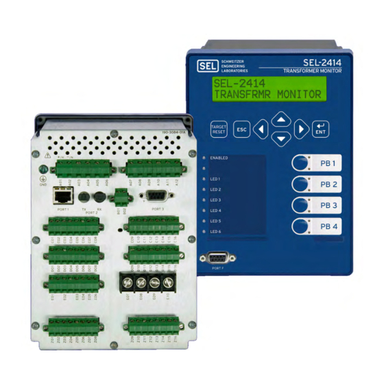
Safety and General Information Laser/LED Emitter The SEL-2414 is a Class 1 LED Product and complies with IEC 60825-1:1993 + A1:1997 + A2:2001. The following figure shows the lower portion of the com- pliance label that is located on the left side of the device (when facing the front of the device). -
Page 14: Safety Warnings And Precautions
Preface Safety and General Information The following figure shows LED location specific to the SEL-2414 (see Figure 2.5–Figure 2.7 for the rear-panel drawings). Optional Fiber-Optic SEL-2414 (partial) (LED) Ports LED Location Specific to the SEL-2414 Safety Warnings and Precautions ➤... -
Page 15: Instructions For Cleaning And Decontamination
Preface Safety and General Information Instructions for Use care when cleaning the SEL-2414. Use a mild soap or detergent solution and a damp cloth to clean the chassis. Do not use abrasive materials, polishing com- Cleaning and pounds, or harsh chemical solvents (such as xylene or acetone) on any surface. - Page 16 This page intentionally left blank...
-
Page 17: Section 1: Introduction And Specifications
This manual contains information necessary to install, test, operate, and maintain any SEL-2414. It is not necessary to review the entire manual to perform specific tasks. Date Code 20130214... -
Page 18: Features
Physical Standard Two isolated dry inputs and three outputs (two Form A and one Form C) Human-Machine-Interface (HMI) One front serial port One rear serial port (compatible with SEL 2810, SEL 2814, SEL 3010, . . .) IRIG B input... -
Page 19: Metering
Options The SEL-2414 contains six slots for cards. Slot A must be used for the power supply and Slot B must be used for the mainboard. The other four slots (Slot C, Slot D, Slot E, and Slot Z) may be configured with option cards that, except for the input/output cards, must be installed in specific slots on the device. -
Page 20: Accessories
4ACI Current Card (Only supported by Slot Z) Accessories For all SEL-2414 mounting accessories, including adapter plates, visit http://www.selinc.com/MountingAccessories. Contact your Technical Service Center or the SEL factory for additional details and ordering information for all other accessories. Table 1.2 Optional Accessories Product... -
Page 21: Applications
Applications Applications General Use the SEL-2414 as a Transformer Monitor to acquire status with digital and analog inputs and provide control with digital outputs. It can also be used to acquire RTD or TC temperature values for transformer thermal monitoring, including top oil temperature if the transformer supports a thermowell for an RTD or TC sensor, or a magnetically mounted sensor has been added. -
Page 22: Single Monitor
Use one Transformer Monitor inside the control house for remote monitoring and remote LTC control. Use a second Transformer Monitor inside the transformer low-voltage compartment for local monitoring and local LTC control. SEL-2414 Transformer Monitor Instruction Manual Date Code 20130214... -
Page 23: Specifications
120 Ω nickel (NI120) RTD types on each 10 Ω copper (CU10) Rated Frequency: 50/60 ± 5 Hz 50/60 ± 5 Hz independent input. Burden: < 0.1 W < 0.1 W Measuring Range: –50°C to 250°C Date Code 20130214 SEL-2414 Transformer Monitor... - Page 24 Voltage Protection Across Impulse Withstand Open Contacts: 270 Vac, 40 J Voltage (U 4000 V Rated Operational 3 A @ 120 Vac Mechanical Durability: 10M no load operations Current (I 1.5 A @ 240 Vac SEL-2414 Transformer Monitor Date Code 20130214...
- Page 25 Note: Make rating per IEEE C37.90 1989. Ymodem file transfer on the front and rear port Xmodem file transfer on the front port Analog Outputs SEL ASCII and Compressed ASCII SEL Fast Meter Current Ranges (Max): ± 20 mA SEL Fast Operate Voltage Ranges (Max): ±10 V...
- Page 26 2 kV @ 5 kHz for comm. ports Digital Inputs Surge Immunity: IEC 60255-22-5:2008 Sampling Rate: 32 times/cycle IEC 61000-4-5:2005 Contact Outputs 2 kV line-to-line Refresh Rate: 32 times/cycle 4 kV line-to-earth Logic Update: 4 times/cycle SEL-2414 Transformer Monitor Date Code 20130214...
- Page 27 1000 A/m for 3 seconds Approvals: Complies with UL1604, CSA 22.2 100 A/m for 1 minute No. 213, and EN 60079-15. EMC Emissions Conducted Emissions: IEC 60255-25:2000, Class A Radiated Emissions: IEC 60255-25:2000, Class A Date Code 20130214 SEL-2414 Transformer Monitor...
- Page 28 This page intentionally left blank...
-
Page 29: Section 2: Installation
You should carefully plan the placement, cable connections, and communication. This section contains drawings of typical ac and dc connections to the SEL-2414. Use these drawings as a starting point for planning your particular application. -
Page 30: Device Placement
Specifications on page 1.7). For EN 61010 certification, the SEL-2414 rating is 2000 m (6560 feet) above mean sea level. Device Mounting To flush mount the SEL-2414 in a panel, cut a rectangular hole with the dimen- sions shown in Figure 2.1. -
Page 31: Card Configuration
Your SEL-2414 offers complete flexibility in tailoring to your specific applica- tion. The SEL-2414 has six rear-panel slots, labeled as Slots A, B, C, D, E, and Z. Slot A and Slot B are fixed, but you can install option cards in expansion Slot C through Slot Z. -
Page 32: Cpu Card Communications Ports
EIA-485) nector for the two protocols. Table 7.5 shows the protocols supported by serial ports and Table 7.6 shows the protocols supported by Ethernet ports. Table 2.3 Communications Card (SEL EIA-232/485) Interfaces and Connectors Terminals Label Description PORT 4A EIA–485 Port 4A, an isolated EIA-485 serial port interface –TX... -
Page 33: Rtd Card (Sel Ect 10 Rtd)
Supported in Slot D only, this card has 10 RTD inputs. Table 2.4 shows the termi- nal allocation. (SEL 10 RTD) Table 2.4 RTD (SEL 10 RTD) Card Terminal Allocation Terminals Label Description RTD1, drives analog quantity RTD1 RTD 1 —... -
Page 34: Voltage Card (3 Avi)
5 A phase CTs and a 1 A neutral CT, or three 1 A phase CTs and a 5 A neutral CT. With a current card installed, the SEL-2414 tracks the fre- quency (using positive-sequence current) and samples at 4 times a cycle—see... -
Page 35: Analog Input Card (8
AIx03, Transducer Input number 3 AI_03 AIx04, Transducer Input number 4 AI_04 AIx05, Transducer Input number 5 AI_05 AIx06, Transducer Input number 6 AI_06 AIx07, Transducer Input number 7 AI_07 AIx08, Transducer Input number 8 AI_08 Date Code 20130214 Instruction Manual SEL-2414 Transformer Monitor... -
Page 36: Analog Input Card (4
(4 AI/4 AO) NOTE: Jumper x (x = 1 through 4) Table 2.11 Four Analog Input/Four Analog Output Card (SEL 4 AI/4 AO) determines the nature of each analog Terminal Allocation output channel. Jumper x (x = 5... -
Page 37: Digital Output Card (8
Supported in any expansion slot (Slot C through Slot Z), this card has eight digi- tal inputs. Table 2.12 shows the terminal allocation. (8 DI) Table 2.12 Eight Digital Input Card (SEL 8 DI) Terminal Allocation Terminals Label Description IN01, drives INx01 element... -
Page 38: Digital Input/Output Card (4
The four outputs are either all normally open contact out- Card (4 DI/4 DO) puts, electromechanical, or fast high-current interrupting outputs. Table 2.14 shows the terminal allocation. Table 2.14 Four Digital Input/Four Digital Output Card (SEL 4 DI/4 DO) Terminal Allocation Terminals Label... - Page 39 Step 6. For an AUTO = Y (Port settings), the device displays the following: =>STA <Enter> SEL-2414 Date: 1/29/2002 Time: 17:18:55 DEVICE Serial Num = 2007036022 FID = SEL-2414-R202-V0-Z003003-D20080429 CID = 0100 PART NUM = 241421AA09X746X1140 SELF TESTS (W=Warn) FPGA GPSB CR_RAM...
-
Page 40: Password And Sel Boot Jumper Selection
SEL operating system called SEL (pins labeled B are not used). In the unlikely BOOT event that the SEL-2414 suffers an internal failure, communications with the device provides a means of download- may be compromised. Forcing the device to SEL BOOT ing new firmware. -
Page 41: Rear-Panel Connections
Not bypassed (not forced SEL Forced SEL BOOT BOOT Rear-Panel Connections Rear-Panel and Side- The physical layout of the connectors on the rear-panel and side-panel diagrams of three sample configurations of the SEL-2414 are shown in Figure 2.5, Panel Diagrams Figure 2.6, and Figure 2.7. - Page 42 Figure 2.6 Dual Fiber Ethernet, EIA-232, 4 DI/4 DO, 10 RTD/TC, 3 CT/3 PT, 3 DI/4 DO (A) Rear-Panel Layout (B) Side-Panel Input and Output Designations Figure 2.7 Dual Fiber Ethernet, Fiber Serial, EIA-232, 3 DO/2 DI, 8 DI, 3 DO/4 DI, 3 PT, 8 AI SEL-2414 Transformer Monitor Instruction Manual Date Code 20130214...
-
Page 43: Power Connections
12. Strip the wires 8 mm (0.31 inches) and install with a small slotted-tip screw- driver. All EIA-232 ports accept 9-pin D-subminiature male connectors. Port 3 includes the IRIG-B time-code signal input (see below). Date Code 20130214 Instruction Manual SEL-2414 Transformer Monitor... -
Page 44: Irig-B Time-Code Input
Two options for IRIG-B signal input are given, but only one may be used at a time. IRIG-B (B01 and B02) inputs or an SEL communications processor via fiber-optic Port 2 or serial Port 3 may be used. See Table 6.19... -
Page 45: Digital Inputs
(Serial) Figure 2.9 Communication Ports Digital Inputs The SEL-2414 optoisolated inputs (e.g., IN102, IN404) are not polarity depen- dent. With nominal control voltage applied, each optoisolated input draws between 2–6 mA of current. Refer to Section 1: Introduction and Specifications for optoisolated input ratings. -
Page 46: Thermocouple Inputs
Figure 2.13 RTD Card and Universal Temperature Card 3-Wire RTD Wiring Thermocouple Calibration Although the thermocouple inputs have been factory calibrated specific to the SEL-2414 system ordered by the user, it is recommended that the user calibrate the installed system to achieve highest thermocouple accuracy. In-Field System Calibration Procedure Step 1. -
Page 47: Rtd Inputs
Maximum lead resistance is 25 Ω . Use 18 to 24 AWG wire gauge for the leads. SEL recommends that you use Belden 8771 or similar cable. Cable shield should be connected to ground at the device (use the COMP/SHLD terminal for shield grounding). -
Page 48: Voltage Connections
SEL-2414 monitors three fan motors. Because the SEL-2414 is not a protection device, be sure to protect the fan motors by means of fuses (F1 through F4) or miniature circuit breakers (not shown). Select appro-... - Page 49 Figure 2.18 Wye-Wye VT Connection SEL-2414 (Partial) Figure 2.19 Open-Delta VT Connection Because the SEL-2414 uses the A-phase voltage as reference when displaying metered values (see MET command), connecting voltages other than the volt- ages shown in Figure 2.17–Figure 2.19 to the device can result in incorrect angle values.
-
Page 50: Field Serviceability
2.22 Installation Field Serviceability Field Serviceability The SEL-2414 firmware may be upgraded in the field; refer to Appendix B: Firm- ware Upgrade Instructions. Configure an output contact to create a diagnostic alarm for a self-test failure as explained in Section 4: Logic Functions. -
Page 51: Section 3: Getting Started
This section presents the fundamental knowledge you need to operate the SEL-2414, organized by task. These tasks help you become familiar with the device and include the following: ➤... -
Page 52: Ac Sel Erator Quickset
ERATOR Overview QuickSet ® SEL-5030 Software is a powerful setting, event analy- ERATOR sis, and measurement tool that aids in setting, applying and using the SEL-2414. Table 3.1 shows the suite of QuickSet applications provided for ERATOR the SEL-2414. Table 3.1... -
Page 53: Connection Parameters
Check the Transformer Monitor Port 2 parameters by selecting SET/SHOW > Port > 2 > Communications Settings on the Transformer Monitor front panel and then using the UP and DOWN pushbuttons to view all of the parameters. Date Code 20130214 Instruction Manual SEL-2414 Transformer Monitor... -
Page 54: Checking Device Status
The last line in the report states whether the device status is enabled or disabled, which depends on whether any particular status field is failed. Table 7.47 provides the definition of each status field. SEL-2414 Transformer Monitor Instruction Manual Date Code 20130214... -
Page 55: Viewing Device Information
QuickSet appli- ERATOR cation, add support for new products (drivers), or update the support for existing ® products (drivers). This selection will launch SEL Compass , the SEL software and literature management application. Manage Databases Select File > Database Manager on the main menu bar to open the database manager or Manage Databases from the launchpad. -
Page 56: Edit (New, Open, Read) Settings
QuickSet uses the Z number in the FID ERATOR string to create a particular version of settings. To get started making SEL-2414 settings with the Device Editor in the Editor Mode, select Settings > New from the main menu bar, and SEL-2414 and 002 from the Settings Editor Selection... -
Page 57: File > Open
QuickSet reads the device ERATOR settings from a connected device. As QuickSet reads the device, a ERATOR Transfer Status window appears. QuickSet uses serial protocols ERATOR to read settings from SEL devices. Date Code 20130214 Instruction Manual SEL-2414 Transformer Monitor... -
Page 58: Help
Select Help from the main menu bar ERATOR QuickSet Device Editor Select SEL-5030 Editor Help from the Device Editor menu SEL-2414 Settings Select Settings Help from the Device Editor menu bar Database manager Select Help from the bottom of the Database Manager... - Page 59 Section 4 Instruction Manual Logic Functions Overview The SEL-2414 Transformer Monitor (TM) provides transformer monitor logic as described in Section 5: Metering and Monitoring. It provides programmable dig- ital and analog logic capabilities that operate on physical inputs and outputs and virtual inputs and outputs, as shown in Figure 4.1...
-
Page 60: Section 4: Logic Functions Overview
Settings for the front-panel display and LED control. Report Settings for the sequential event reports. Settings for DNP communications. Logical Operators Logical operators can be used in any SEL equation; they are shown in OGIC Table 4.2. Use the comparison operators with Analog Quantities (e.g., IA, IB, IC);... -
Page 61: Mathematical Operators
Negation – Multiply Divide Subtract Function Blocks Function block outputs can be used in any SEL equation; the function blocks OGIC and their outputs are shown in Table 4.4. Likewise, logical operators can be used in any of the SEL equations that drive the function blocks. -
Page 62: General Logic Functions
Traditional latching devices maintain output contact state. The SEL-2414 latches also retain state even when power to the device is lost. If the latch is set to a programmable output contact and power to the device is lost, the state of the latch is stored in nonvolatile memory, but the device de-energizes the output contact. -
Page 63: Power Loss
SETn and RSTn, the inputs each have a separate debounce timer that can help in providing the necessary time qualifica- tion. Variables/Timers Operation Each SEL control equation variable/timer has a SEL control equation OGIC OGIC setting input and variable/timer outputs as shown in Figure 4.6. -
Page 64: Sv/Timers Set
Device Word bits SVn and SVnT (n = 01–64) reset to logical 0 after power restoration or a settings change. Figure 4.7 shows an effective seal-in logic circuit, created by the use of Device Word bit SV07 (SEL control OGIC equation variable SV07) in SEL... - Page 65 (SCn = 0, n = 01 to 32). SCnn Output Value This counter output is an analog value that may be used with analog comparison operators in a SEL control OGIC equation and viewed using the COU command. Figure 4.9 shows an example of the effects of the input precedence, with SC01PV set to 7.
-
Page 66: Math Variables
–16777215.99. Similarly, when the MV02 := executed result is +16777238.00, MV02 will be +16777215.99. Output Contacts The SEL-2414 provides the ability to use SEL control equations to map OGIC logic outputs to the physical outputs. You must enter an equation for the output settings. -
Page 67: Sel Ogic Control Equation Operators
Operator Precedence When you combine several operators and operands within a single expression, the SEL-2414 evaluates the operators from left to right, starting with the highest precedence operators and working down to the lowest precedence. Table 4.8 Control Equation Operators (Listed in Operator Precedence) - Page 68 Boolean Equality (=) and Inequality (<>) Operators Equality and inequality operators operate similar to the comparison operators. Other Table 4.9 shows other operators and values that you can use in writing SEL OGIC control equations. Table 4.9 Other SEL Control Equation Operators/Values...
-
Page 69: Section 5: Metering And Monitoring
Section 5 Instruction Manual Metering and Monitoring Overview The SEL-2414 Transformer Monitor provides the transformer metering and mon- itoring functions shown in Table 5.1 Table 5.2. Some settings will have to be changed from the factory-default settings so these features operate properly for your installation. -
Page 70: Metering
RTD Metering There are two ways to get RTD readings on the SEL-2414. One is by installing an RTD card. These readings will be referred to as “internal RTD”. The other way is to connect the SEL-2414 to an SEL-2600. These readings will be referred to as “external RTDs”. -
Page 71: Rtd/Tc Metering
Fundamental Table 5.6 details each of the eight cycle-averaged meter data types in the SEL-2414. These values are listed if the appropriate cards are installed and if Metering they are not inhibited by the type of transformer connection (see Transformer Nameplate Application Description on page 5.11... -
Page 72: Power Measurement Conventions
DELTA_Y := DELTA and VAB > 13 V No voltages or VAN < 13 V or VAB 13 V Power Measurement Conventions The SEL-2414 uses the IEEE convention for power measurement assuming motor action, as shown in Figure 5.3 Figure 5.4. -
Page 73: Energy Metering
= lagging pf = leading Figure 5.4 Complex Power Measurement Conventions—Motor Action In the SEL-2414, reported positive real power is always into the load. See Section 7: Communications for examples of the device response to power mea- surement in the four quadrants. -
Page 74: Demand Metering
Depending on enable setting EDEM, these demand and peak demand values are thermal demand or rolling demand values. The differences between thermal and rolling demand metering are explained in the following subsection. SEL-2414 Transformer Monitor Instruction Manual Date Code 20130214... -
Page 75: Thermal Demand (Edem := Thm)
DMTC period. Rolling demand metering response is at 100 percent (1.0 per unit) of the full applied value after a time equal to the fourth DMTC period (see (d) in Figure 5.6). Date Code 20130214 Instruction Manual SEL-2414 Transformer Monitor... -
Page 76: Demand Meter Settings
Demand Metering Updating and Storage The SEL-2414 updates demand values approximately every two seconds. The SEL-2414 stores peak demand values to nonvolatile storage once per day and overwrites the previous stored value if it is exceeded. Should the controller lose control power, it will restore the peak demand values saved by the device at 23:50 hours on the previous day. -
Page 77: Math Variable Metering
=>> Figure 5.8 Device Response to the MET MV Command When Global Setting DELTA_Y = DELTA, you still may use the phase-to-neutral voltage quantities (VA, VB, VC) in math variable equations, but the SEL-2414 zeroes these values out. Remote Analog Use remote analog metering to verify the values received from an external device. -
Page 78: Thermal Element
Analog Signal Profiling Thermal Element Application Description The SEL-2414 provides a thermal element based on IEEE Standard C57.91-1995, IEEE Guide for Loading Mineral-Oil-Immersed Power Transform- ers. Use this element to activate a control action or issue a warning or alarm when your transformer overheats or is in danger of excessive insulation aging or loss of life. -
Page 79: Transformer Nameplate Application Description
In this mode, the SEL-2414 only requires measured current from one phase to determine the load on the transformer. If more than one phase measurement is provided as shown in Figure 5.10, the thermal model will use the highest mea-... - Page 80 3AVI/3ACI card in Slot E to use the different CT ratio settings for each CT input, or use math variables to provide the appropriate multiplication factor for each measured phase current and set TMWAQ to use the respective math variables. SEL-2414 Transformer Monitor Instruction Manual Date Code 20130214...
-
Page 81: Operating Characteristic
Metering and Monitoring 5.13 Monitoring When the SEL-2414 is connected in this mode, no power calculations can be made because each CT is monitoring current on a different winding. See Table I.1 for a list of which metering quantities are set to 0 when ETHERM = W. -
Page 82: Temperature Inputs To The Thermal Element
(if MTOx_OK is asserted, Figure 5.15), the thermal element uses that as an input to the hot-spot temperature calculation, as shown in Figure 5.16 (A). If a SEL-2414 Transformer Monitor Instruction Manual Date Code 20130214... -
Page 83: Cooling Stage Determination
Cooling stages are defined as follows: Stage 1 is passive cooling (i.e., ONAN), Stage 2 is the first level of active cooling (i.e., ONAF), and Stage 3 is the second level of active cooling (i.e., ONAF with second stage fans or OFAF or ODAF). Date Code 20130214 Instruction Manual SEL-2414 Transformer Monitor... -
Page 84: Thermal Element Calculations
Figure 5.13, the active cooling stage is an input into the thermal model and does not provide direct control output to cooling equipment. Separate cooling logic may be written to control fans and oil pumps using SEL con- OGIC trol equations, but the bits in this section do not provide that functionality. The... - Page 85 = the ultimate hot-spot rise over top-oil temperature at given load, °C ΔΘ = initial hot-spot rise over top-oil temperature at the start time of the interval, °C = thermal time constant of hot spot, in hours (set from Table 5.14) Date Code 20130214 Instruction Manual SEL-2414 Transformer Monitor...
-
Page 86: Insulation Loss Of Life
ETHERM = 1, only T1RLOL is calculated. When ETHERM = 3, T1RLOL, T2RLOL, and T3RLOL are calculated. When ETHERM = W, W1RLOL, W2RLOL, and W3RLOL are calculated. SEL-2414 Transformer Monitor Instruction Manual Date Code 20130214... - Page 87 = previous TLOL (from yesterday) d–1 The device stores the TLOL value at midnight each day. You can use the THE P command to load an initial value of TLOL into the device. Date Code 20130214 Instruction Manual SEL-2414 Transformer Monitor...
-
Page 88: Thermal Probe Selection Settings Descriptions
(T1_OILM) is known to be invalid or faulted. T1OIL_F is used to set MT01_OK, as shown in Figure 5.15. Note: MT01_OK will automatically deassert if T1_OILM goes outside the range (–50 to +250). SEL-2414 Transformer Monitor Instruction Manual Date Code 20130214... -
Page 89: Thermal Element Settings Descriptions
Transformer 2 MVA rating to calculate rated current. The relay then divides measured current by the rated current to determine K (per unit load) that the relay uses in thermal element calculations. Date Code 20130214 Instruction Manual SEL-2414 Transformer Monitor... - Page 90 Cooling Stage 3 would include both first and second stage of cooling fans or cooling fans and oil circulation pump. Set NUMCS to the maximum number of cooling stages associated with the monitored power transformer. SEL-2414 Transformer Monitor Instruction Manual Date Code 20130214...
- Page 91 CS3 (forced-oil and air cooled OFAF) MVA1CS3 = 170 ETHERM = 3 Cooling System MVA Rating Transformer 1 Transformer 2 Transformer 3 MVA1CS1 = 100 MVA2CS1 = 100 MVA3CS1 = 100 (natural oil and air cooled ONAN) Date Code 20130214 Instruction Manual SEL-2414 Transformer Monitor...
- Page 92 SEL-2414 with the CsxyS SEL control equations set to the corresponding digital input.
-
Page 93: Thermal Alarm Limits
One of the outputs the thermal element provides is winding hot-spot temperature. HST1 and HST2 determine limits for hot-spot temperature alarming. If the hot- spot temperature exceeds one of these limits, the corresponding HS1 or HS2 Device Word bit asserts. Using SEL control equations, you can configure OGIC... - Page 94 Should load and temperature be less than normal, the factor is less than 100 percent. FAAL1 and FAAL2 determine limits for the aging acceleration factor. If the aging acceleration factor exceeds the limits, the FAA1 or FAA2 Device Word bit asserts. Using SEL control equations, you can configure OGIC these Device Word bits to close alarm contacts.
- Page 95 (in percent) of the life lost from the relay during a 24-hour period. RLOLL determines a limit for daily rate of loss-of-life. If the daily rate of loss-of-life exceeds the limit, a RLL Device Word bit asserts. Using SEL OGIC control equations, you can configure the RLL Device Word bit to close an alarm contact.
- Page 96 Winding 2 T2TLOL or W2TLOL TLL Logic TLOLL (Setting) TLL_3, W3_TLL Winding 3 T3TLOL or W3TLOL TLL Logic TLOLL (Setting) ENABLED IF ETHERM = 3 OR W Figure 5.21 Total Loss-of-Life Alarm Logic SEL-2414 Transformer Monitor Instruction Manual Date Code 20130214...
- Page 97 = 3. Enable Default Constants (EDFTC). Range: Y, N Setting EDFTC enables or disables the default transformer cooling stage constants in Default Transformer Constants, as listed in Table 5.14. Date Code 20130214 Instruction Manual SEL-2414 Transformer Monitor...
- Page 98 You can select other values from within a range of 0 to 100000. The thermal element uses this constant to calculate the transformer insulation aging acceleration factor (FAA). SEL-2414 Transformer Monitor Instruction Manual Date Code 20130214...
-
Page 99: Cooling Stage N Constants
The oil thermal time constant is the time it takes the top-oil temperature rise over ambient temperature to reach 63.2 percent of the difference between final rise and initial rise during a load change. If not provided, OTR can be calculated from the following equation. Date Code 20130214 Instruction Manual SEL-2414 Transformer Monitor... - Page 100 The default values listed in Table 5.14 are from IEEE C57.92-1981, Tables 2 and 4. If specific values for a particular transformer are known, you can enter values from within a range of 0 to 5. SEL-2414 Transformer Monitor Instruction Manual Date Code 20130214...
-
Page 101: Thermal Element Condition
Viewing Information The thermal report functions provide information about the thermal status of the transformer(s) monitored by the SEL-2414 Transformer Monitor. There are four different types of reports that display the present thermal status: thermal monitor report, thermal event reports, hourly profile data, and daily profile data. - Page 102 Thermal Element Condition :NORMAL NORMAL NORMAL single-phase transformers Load(Per Unit) :0.96 1.00 1.01 (ETHERM = 3), the SEL-2414 displays In Service Cooling Stage :3 the values for Transformer 1, Ambient (deg. C) :15.0 15.0 15.0 Transformer 2, and Transformer 3.
- Page 103 Whenever a thermal alarm condition is set (load conditions are Warning 1, Warn- ing 2, or Warning 3), the SEL-2414 saves a snapshot of the thermal status of the transformer(s) in nonvolatile memory. The five most recent thermal events are saved.
- Page 104 The command must be followed by a value between zero and 100 per- cent. This command initializes the total loss-of-life value to the preset value entered by the user and restarts the thermal element. Thermal archive data are not cleared. SEL-2414 Transformer Monitor Instruction Manual Date Code 20130214...
-
Page 105: Through-Fault Event Monitor
Note that the calculated currents are in primary values. • • ----------------------------------------------- - Equation 5.22 MAG_PU Date Code 20130214 Instruction Manual SEL-2414 Transformer Monitor... - Page 106 (in percent) at the TRFRZ setting. Table 5.18 Default Transformer Constants Setting Description Range (Y,N) ETHFLTM Enable Through-Fault Monitoring ETHRFLT Enable Through-Fault Monitor (SEL control control OGIC OGIC equation). Deassert during testing. equation THFLTPU Through-Fault Alarm Pickup 50.0–900.0%...
-
Page 107: Meaning Of Accumulated Through-Fault Capability
Based upon the magnitude and duration of each fault, the event is compared to the through-fault protection curve shown in Figure 5.26. If the fault is severe enough that it reaches the protection Date Code 20130214 Instruction Manual SEL-2414 Transformer Monitor... -
Page 108: Through-Fault Monitor Report (Tfe Command)
500 through-faults events. Under the date and time columns, the event shows the date of occurrence and the start time of each event (The date format dependents upon the DATE_F setting). SEL-2414 Transformer Monitor Instruction Manual Date Code 20130214... -
Page 109: Analog Signal Profiling
SPLIST1 or SPLIST2 settings, for a total of 32 analog quantities. Choose from the analog quantities in Appendix I: Analog Quantities. Table 5.20 shows the set- tings for the Signal Profile List. Date Code 20130214 Instruction Manual SEL-2414 Transformer Monitor... - Page 110 Signal Profile Enable Enter up to 14 nested parentheses and up to 15 elements. At the data acquisition rate of 5 minutes, the SEL-2414 stores at least 10 days of all analog signals selected for profiling in nonvolatile memory. The report includes the time of acquisitions and the magnitude of each selected analog quantity.
-
Page 111: Section 6: Settings
Section 3: Getting Started for detailed information. Setting entry error messages, together with corrective actions, are also presented in this section to assist correct settings entry. The SEL-2414 settings sheets at the end of this section list all SEL-2414 settings. Date Code 20130214... -
Page 112: View/Change Settings Using The Front Panel
Enter pushbutton, and the device Device will present you with the Device settings as listed in the SEL-2414 settings sheets. Use the Up Arrow, Down Arrow, Left Arrow, and Right Arrow pushbuttons to scroll through the Device settings and view/change them according to your needs by selecting and editing them. -
Page 113: View/Change Settings Over Communications Port
View Settings Use the SHOW command to view Device settings. The SHOW command is available from Access Level 1 and Access Level 2. Table 6.2 lists the SHOW command options. Date Code 20130214 Instruction Manual SEL-2414 Transformer Monitor... -
Page 114: Enter Settings
Press Key Results <Enter> Retains the setting and moves to the next setting ^<Enter> Returns to the previous setting <<Enter> Returns to the previous setting category ><Enter> Moves to the next setting category SEL-2414 Transformer Monitor Instruction Manual Date Code 20130214... -
Page 115: Device Settings (Set Command)
Under the Device setting category, we set the device and terminal identifiers, set- tings pertaining to the analog (transducer) input (AI) cards, analog output (AO) cards, and transformers. The SEL-2414 displays the Device and Terminal Identi- fier strings at the top of responses to serial port commands identifying messages from individual devices. -
Page 116: Analog Inputs
±1 uA or ±1 mV. Signal offset compensation factor calculation procedure: 1. Turn the SEL-2414 on and allow it to warm up for a few minutes. 2. Set the analog inputs for each analog channel to the desired range (e.g., ±1 mA), using the AIxxxTYP, AIxxxL, and AIxxxH settings. -
Page 117: Analog Input Setting Example
Section 2: Installation for more infor- mation) for Input 1 to operate as a current input. At powerup, allow approxi- mately five seconds for the SEL-2414 to boot up, perform self-diagnostics, and detect installed cards. Table 6.7 summarizes the steps and describes the settings we will carry out in this example. - Page 118 AI302 Instrument Tag Name (8 characters 0-9,A-Z,_) AI302NAM:= AI302 ? END <Enter> Save changes (Y,N)? Y <Enter> Settings Saved =>> Figure 6.3 Settings to Configure Input 1 as a 4–20 mA Transducer, Measuring Temperatures Between –50°C and 150°C SEL-2414 Transformer Monitor Instruction Manual Date Code 20130214...
-
Page 119: Analog Input Settings
Slot 3. For the name setting (AI301NAM, for example), enter only alphanumeric and underscore characters. Characters are not case sensitive, Date Code 20130214 Instruction Manual SEL-2414 Transformer Monitor... - Page 120 := 20.000 ? <Enter> Analog Output 402 Settings AO402 Analog Quantity (1 analog quantity) AO402AQ := OFF ? END <Enter> Save changes (Y,N)? Y <Enter> Settings Saved =>> Figure 6.5 Analog Output Settings SEL-2414 Transformer Monitor Instruction Manual Date Code 20130214...
-
Page 121: Internal Rtd Inputs
None CU10, NONE IRTD10TY Internal RTD Card PT100, NI100, NI120, None CU10, NONE External RTD Inputs Table 6.11 Input Settings for External RTD from SEL-2600 Devices Setting Setting Name := Description Setting Range Prompt Factory Default ERTD1TY External RTD from... -
Page 122: Universal Temperature Inputs
The phase rotation setting tells the device your phase labeling standard. Set PHROT equal to ABC when B-phase lags A-phase by 120 degrees. Set PHROT equal to ACB when B-phase leads A-phase by 120 degrees. SEL-2414 Transformer Monitor Instruction Manual Date Code 20130214... -
Page 123: Event Messenger Points
148 characters MPTX5 := The SEL-2414 can be configured to automatically send ASCII message on a communications port when trigger condition is satisfied. Use the SET P command to set PROTO := EVMSG on the desired port to select the port. This feature is designed to send messages to the SEL-3010 Event Messenger, however, any device capable of receiving ASCII messages can be used. -
Page 124: Digital Input Configuration
Formatted message out when triggered: THE LOAD CURRENT IS 157 AMPERES Digital Input You can configure the SEL-2414 with up to four DI cards, one in each of the four available slots (slots C, D, E, and Z). Because of the flexibility of inserting I/O Configuration cards in any of the assigned slots, each connection has two numbers. -
Page 125: Digital Input Debounce
This information is useful to time-align events from two unsynchronized devices when one device operated on receipt of the output from the other device. To this end, the SEL-2414 provides both the time of first assertion information as well as the delayed time information as separate Device Word bits when set to the dc debounce mode. - Page 126 Timer 1 is running, Debounce Timer 1 resets, and starts timing from the begin- ning at the next rising edge. When changing from the asserted state to the deasserted state, the inverse opera- tion applies, as shown in Figure 6.9. SEL-2414 Transformer Monitor Instruction Manual Date Code 20130214...
- Page 127 Timer 1 (do) Starts Timer 1 (do) Starts IN101 Debounce Timer 1 (do) Stops IN101 Deasserts Figure 6.9 Timing Diagram When Input IN101 Changes From the Asserted State to the Deasserted State Date Code 20130214 Instruction Manual SEL-2414 Transformer Monitor...
-
Page 128: Ac Mode Processing (Ac Control Voltage)
If IN101R remains deasserted for a period longer than the dropout timer setting, then Device Word bit IN101 deasserts to a logical 0. Table 6.17 shows the settings prompt, setting range, and factory default settings for a card in Slot 3. SEL-2414 Transformer Monitor Instruction Manual Date Code 20130214... -
Page 129: Data Reset
Use the Time Synchronization Source Setting to declare the source of Source the IRIG input. The SEL-2414 accepts IRIG input from either Port 2 or Port 3. If the IRIG source is Port 3, select IRIG1 as the setting. If the IRIG source is Port 2 (fiber-optic port), select IRIG2 as the setting. - Page 130 This page intentionally left blank...
-
Page 131: Sel-2414 Settings Sheets
The settings are not case sensitive. Device Settings (SET Command) Device Settings Device Identification (16 characters) Terminal ID (16 characters) Transformer Settings Current Transformer Ratio (1–5000) (Shown if SEL ACI) Neutral Current Transformer Ratio (1–5000) (Shown if CTRN 4 ACI) X Currents Transformer Ratio (1–5000) CTRX 3 ACI/3 AVI and ETHERM ≠... - Page 132 SET.2 SEL-2414 Settings Sheets of 36 AIx01 Engineering Units (16 characters) AIx01EU AIx01 Engineering Unit Low (–99999.000 to +99999.000) AIx01EL AIx01 Engineering Unit High (–99999.000 to +99999.000) AIx01EH AIx01 Low Warn Level 1 (OFF, –99999.000 to +99999.000) AIx01LW1 AIx01 Low Warn Level 2 (OFF, –99999.000 to +99999.000) AIx01LW2 AIx01 Low Alarm (OFF, –99999.000 to +99999.000)
- Page 133 SEL-2414 Settings Sheets SET.3 of 36 Analog Input x04 Settings AIx04 Instrument Tag Name (8 characters 0–9, A–Z, _) AIx04NAM := AIx04 Type (I, V) AIx04TYP If AIx04TYP = I AIx04 Low (–20.480 to +20.480; mA) AIx04L AIx04 High (–20.480 to +20.480; mA)
- Page 134 SET.4 SEL-2414 Settings Sheets of 36 If AIx06TYP = V AIx06 Low (–10.240 to +10.240 V) AIx06L (–300 to +300 V Extended Range) AIx06 High (–10.240 to +10.240 V) AIx06H (–300 to +300 V Extended Range) AIx06EU AIx06 Engr Units (16 characters) AIx06 Engr Low (–99999.000 to +99999.000)
- Page 135 SEL-2414 Settings Sheets SET.5 of 36 AIx08EU AIx08 Engr Units (16 characters) AIx08 Engr Low (–99999.000 to +99999.000) AIx08EL AIx08 Engr High (–99999.000 to +99999.000) AIx08EH AIx08 Low Warn 1 (OFF, –99999.000 to +99999.000) AIx08LW1 AIx08 Low Warn 2 (OFF, –99999.000 to +99999.000) AIx08LW2 AIx08 Low Alarm (OFF, –99999.000 to +99999.000)
- Page 136 IRTD8TY RTD9 TYPE (PT100, NI100, NI120, CU10, NONE) IRTD9TY RTD10 TYPE (PT100, NI100, NI120, CU10, NONE) IRTD10TY External RTD Via SEL-2600 Devices RTD1 TYPE (PT100, NI100, NI120, CU10, NONE) ERTD1TY RTD2 TYPE (PT100, NI100, NI120, CU10, NONE) ERTD2TY RTD3 TYPE (PT100, NI100, NI120, CU10, NONE)
- Page 137 Number of Cooling Stages (1–3) NUMCS (Hidden if ETHERM = N) Enable Transformer Thermal Monitoring (N, 1, 3, W) ETHERM TRFR 1 Cooling Stage 2 Activation (SEL T1CS2 OGIC (Hidden if NUMCS < 2) TRFR 1 Cooling Stage 3 Activation (SEL...
- Page 138 SET.8 SEL-2414 Settings Sheets of 36 Hot-Spot Cond. Rise/Top Oil (0.1–100.0 deg. C) T1THGR1 Ratio Losses (0.1–100.0) T1RATL1 Oil Thermal Time Constant (0.10–20.00 hrs) T1OTR1 Oil Exponent (0.1–5.0) T1EXPN1 Winding Exponent (0.1–5.0) T1EXPM1 Cooling Stage 2 Constants, Transformer 1 (Hidden if ETHERM = N or NUMCS < 2) TRFR 1 MVA Rating Cooling Stage 2 (1.00–1000.00 MVA) MVA1CS2...
- Page 139 SEL-2414 Settings Sheets SET.9 of 36 Oil Thermal Time Constant (0.10–20.00 hrs) T2OTR3 Ratio Losses (0.1–100.0) T2RATL3 (Hidden if ETHERM = W) Oil Exponent (0.1–5.0) T2EXPN3 (Hidden if ETHERM = W) Winding Exponent (0.1–5.0) T2EXPM3 Cooling Stage 1 Constants, Transformer 3 (Hidden if ETHERM ¹...
- Page 140 SET.10 SEL-2414 Settings Sheets of 36 TRFR 3 Cooling System Efficiency (5–100 deg. C) T3CSEP Aging Acceleration Factor Limit 1 (0.00–599.99) FAAL1 Aging Acceleration Factor Limit 2 (0.00–599.99) FAAL2 Daily Loss-of-Life Limit (0.000–99.999 %) RLOLL Total Loss-of-Life Limit (0.000–99.999 %)
-
Page 141: Logic Settings (Set L Command)
SEL-2414 Settings Sheets SET.11 Logic Settings (SET L Command) of 36 Logic Settings (SET L Command) Enables OGIC Latches (N, 1–32) ELAT OGIC Variables/Timers (N, 1–64) OGIC Counters (N, 1–32) OGIC Math Variables Equations (N, 1–32) OGIC Latch Bit Set/Reset Equations... - Page 142 SET.12 SEL-2414 Settings Sheets of 36 Logic Settings (SET L Command) SET22 RST22 SET23 RST23 SET24 RST24 SET25 RST25 SET26 RST26 SET27 RST27 SET28 RST28 SET29 RST29 SET30 RST30 SET31 RST31 SET32 RST32 Variable/Timer Settings OGIC Variable Input (SV) SV01 OGIC Variable Timer Pickup (0.000–16000.000 sec)
- Page 143 SEL-2414 Settings Sheets SET.13 Logic Settings (SET L Command) of 36 Variable Input (SV) SV10 OGIC Variable Timer Pickup (0.000–16000.000 sec) SV10PU OGIC Variable Timer Dropout (0.000–16000.000 sec) SV10DO OGIC Variable Input (SV) SV11 OGIC Variable Timer Pickup (0.000–16000.000 sec)
- Page 144 SET.14 SEL-2414 Settings Sheets of 36 Logic Settings (SET L Command) Variable Input (SV) SV27 OGIC Variable Timer Pickup (0.000–16000.000 sec) SV27PU OGIC Variable Timer Dropout (0.000–16000.000 sec) SV27DO OGIC Variable Input (SV) SV28 OGIC Variable Timer Pickup (0.000–16000.000 sec)
- Page 145 SEL-2414 Settings Sheets SET.15 Logic Settings (SET L Command) of 36 Variable Input (SV) SV44 OGIC Variable Timer Pickup (0.000–16000.000 sec) SV44PU OGIC Variable Timer Dropout (0.000–16000.000 sec) SV44DO OGIC Variable Input (SV) SV45 OGIC Variable Timer Pickup (0.000–16000.000 sec)
- Page 146 SV64DO OGIC Counter Settings OGIC Counter Preset Value SCxxPV (1–65000) SC01PV Counter Reset Input SCxxR (SEL SC01R OGIC Counter Load PV Input SCxxLD (SEL SC01LD OGIC Count Up Input ScxxCU (SEL SC01CU OGIC Count Down Input SCxxCD (SEL SC01CD OGIC Counter Preset Value SCxxPV (1–65000)
- Page 147 Logic Settings (SET L Command) of 36 Counter Preset Value SCxxPV (1–65000) SC07PV Counter Reset Input SCxxR (SEL SC07R OGIC Counter Load PV Input SCxxLD (SEL SC07LD OGIC Count Up Input ScxxCU (SEL SC07CU OGIC Count Down Input SCxxCD (SEL...
- Page 148 36 Logic Settings (SET L Command) Counter Preset Value SCxxPV (1–65000) SC16PV Counter Reset Input SCxxR (SEL SC16R OGIC Counter Load PV Input SCxxLD (SEL SC16LD OGIC Count Up Input ScxxCU (SEL SC16CU OGIC Count Down Input SCxxCD (SEL...
- Page 149 Logic Settings (SET L Command) of 36 Counter Preset Value SCxxPV (1–65000) SC25PV Counter Reset Input SCxxR (SEL SC25R OGIC Counter Load PV Input SCxxLD (SEL SC25LD OGIC Count Up Input ScxxCU (SEL SC25CU OGIC Count Down Input SCxxCD (SEL...
- Page 150 SET.20 SEL-2414 Settings Sheets of 36 Logic Settings (SET L Command) Math Variable SEL Equations OGIC MV01 MV02 MV03 MV04 MV05 MV06 MV07 MV08 MV09 MV10 MV11 MV12 MV13 MV14 MV15 MV16 MV17 MV18 MV19 MV20 MV21 MV22 MV23 MV24...
- Page 151 SEL-2414 Settings Sheets SET.21 Logic Settings (SET L Command) of 36 For a Card in Slot 4 OUT401 OUT402 OUT403 OUT404 OUT405 OUT406 OUT407 OUT408 For a Card in Slot 5 OUT501 OUT502 OUT503 OUT504 OUT505 OUT506 OUT507 OUT508 For a Card in Slot 6...
- Page 152 SET.22 SEL-2414 Settings Sheets of 36 Logic Settings (SET L Command) Global Settings (SET G Command) General Settings Phase Rotation (ABC, ACB) PHROT Rated Frequency (50, 60 Hz) FNOM Transformer Connection (DELTA, WYE) DELTA_Y Date Format (MDY, YMD, DMY) DATE_F Input Debounce Settings (Base Unit) IN101 Debounce (AC, 0–65000 ms)
- Page 153 Disable FP Settings Change (SV) DSABLSET := Time Synchronization Source TIME_SRC IRIG Time Source (Select: IRIG1, IRIG2) TIME_SRC := Voltage Ratio Correction Factors (only visible when SEL 3 ACI/3 AVI 0–8 Vac card installed) VARCF Ratio Correction Factor (Range = 0.500–1.500) VARCF VBRCF Ratio Correction Factor (Range = 0.500–1.500)
- Page 154 Hidden if DNP not supported Port 2 Port Enable (Y, N) EPORT Maximum Access Level (ACC, 2AC) MAXACC Protocol (SEL, DNP, MOD, MBA, MBB, MB8A, MB8B, MBTA, MBTB, PROTO EVMSG, RTD) Speed (300 to 38400 bps) SPEED Data Bits (7, 8 bits)
- Page 155 Fast Operate Messages (Y, N) FASTOP Port 3 Port Enable (Y, N) EPORT Maximum Access Level (ACC, 2AC) MAXACC Protocol (SEL, DNP, MOD, MBA, MBB, MB8A, MB8B, MBTA, MBTB, PROTO EVMSG, RTD) Speed (300 to 38400 bps) SPEED Data Bits (7, 8 bits) BITS...
- Page 156 SET.26 SEL-2414 Settings Sheets of 36 Logic Settings (SET L Command) RMB7 Dropout Debounce Messages (1–8) RMB7DO RMB8 Pickup Debounce Messages (1–8) RMB8PU RMB8 Dropout Debounce Messages (1–8) RMB8DO Telnet Telnet Port (23, 1025–65534) TPORT Telnet Port Timeout (1–30 min)
- Page 157 SEL-2414 Settings Sheets SET.27 Logic Settings (SET L Command) of 36 DNP3 Session Map (1–3) DNPMAP2 Analog Input Default Variation (0–6) DVARAI2 Class for binary event data, 0 disables (0–3) ECLASSB2 Class for counter event data, 0 disables (0–3) ECLASSC2 Class for analog event data, 0 disables (0–3)
- Page 158 SET.28 SEL-2414 Settings Sheets of 36 Logic Settings (SET L Command) Serial Port Settings Minimum delay from DCD to TX, seconds (0.00–1.00) MINDLY Maximum delay from DCD to TX, seconds (0.00–1.00) MAXDLY Settle time from RTS on to TX; Off disables PSTDLY (OFF, 0.00–30.00) PREDLY Settle time from TX to RTS off (0.00–30.00)
- Page 159 SEL-2414 Settings Sheets SET.29 Logic Settings (SET L Command) of 36 Front-Panel Settings (SET F Command) General Settings Enable Display Points (N, 1–32) Enable Local Bits (N, 1–32) LCD Timeout (OFF, 1–30; min) FP_TO LCD Contrast (1–8) FP_CONT LED Settings...
- Page 160 SET.30 SEL-2414 Settings Sheets of 36 Logic Settings (SET L Command) DP16 DP17 DP18 DP19 DP20 DP21 DP22 DP23 DP24 DP25 DP26 DP27 DP28 DP29 DP30 DP31 DP32 Local Bit Settings Local Bit LB_ Name (14 Char; Enter NA to Null) NLB01 Clear Local Bit LB_ Label (7 Char;...
- Page 161 SEL-2414 Settings Sheets SET.31 Logic Settings (SET L Command) of 36 Clear Local Bit LB_ Label (7 Char; Enter NA to Null CLB09 Set Local Bit LB_ Label (7 Char; Enter NA to Null) SLB09 Pulse Local Bit LB_ Label (7 Char; Enter NA to Null) PLB09 Local Bit LB_ Name (14 Char;...
- Page 162 SET.32 SEL-2414 Settings Sheets of 36 Logic Settings (SET L Command) Local Bit LB_ Name (14 Char; Enter NA to Null) NLB22 Clear Local Bit LB_ Label (7 Char; Enter NA to Null CLB22 Set Local Bit LB_ Label (7 Char; Enter NA to Null) SLB22 Pulse Local Bit LB_ Label (7 Char;...
- Page 163 SEL-2414 Settings Sheets SET.33 Logic Settings (SET L Command) of 36 Report Settings (SET R Command) Event Report Settings Event Trigger (SV) Event Length (15, 64 cyc) Prefault Length (1–10 cyc) or (1–59 cyc) SER Chatter Criteria Auto-Removal Enable (Y, N) ESERDEL Number of Counts (2–20)
- Page 164 SET.34 SEL-2414 Settings Sheets of 36 Logic Settings (SET L Command) Fast Message Read Settings Enter up to 24 Analog Quantities separated by spaces or commas in each of the four lists. Use NA to disable setting. FMR1 NAME (9 characters)
- Page 165 SEL-2414 Settings Sheets SET.35 Logic Settings (SET L Command) of 36 Signal Profile Settings Enter up to 16 Analog Quantities separated by spaces or commas in each list. Use NA to null. Signal Profile List SPLIST1 Signal Profile List SPLIST2...
- Page 166 This page intentionally left blank...
-
Page 167: Section 7: Communications
Access levels in this device are Access Level 0, Access Level 1, and Access Level 2. Communications Communications Table 7.1 shows the physical interfaces of the SEL-2414 Transformer Monitor. Several options are available to provide alternative physical interfaces, including Ports EIA-485 and fiber-optic cable (see Section 2: Installation for more information on the interface cards). -
Page 168: Irig
+5 Vdc Power Supply Serial port power provides as much as 0.5 A total from all of the +5 Vdc pins (Port F, Port 3, and Port 4A). Some SEL communications devices require the NOTE: Although the +5 Vdc power +5 Vdc power supply. -
Page 169: Sel-2414 Cable Connections To Communications Devices
For EIA-485, the pin numbers represent device terminals C01 through C05. The following cable diagrams show several types of EIA-232 serial communica- tions cables that connect the SEL-2414 to other devices. These and other cables are available from SEL. SEL-2414 Cable Connections to Communications Devices Table 7.4 Communications Cables... -
Page 170: Communications Protocols
Fast SER This protocol is used to receive binary Sequential Events Recorder unsolicited responses. Fast Message Read This protocol uses binary messages to transmit data to an SEL Communications Processor. See Appendix C: SEL Communications Processors for details. Fast Message Unsolicited Write This protocol uses binary messages to receive data from an SEL Communications Processor. -
Page 171: Ethernet Protocols (Port 1A, 1B)
FTP is a standard TCP/IP protocol for exchanging files. Telnet Server Use Telnet to connect to the device to use SEL protocols (SEL ASCII, Compressed ASCII, Fast Meter, and Fast Operate). Telnet is a terminal connection across a TCP/IP network that operates in a manner very similar to a direct serial port connection to one of the device ports. -
Page 172: Access Commands (Access And 2Access)
Table 7.8. Different commands are available at the different access lev- (ACCESS and els, as shown in the SEL-2414 Transformer Monitor Command Summary at the 2ACCESS) end of this manual. Commands ACC and 2AC are explained together because they operate similarly. The alarm contact closes for one second upon entry of 2AC and if the incorrect password is entered three times for any access level. -
Page 173: Example 1
4–20 mA for a 9.0 minute test. To check the device output, calculate the current/time (mA/min) output as fol- lows: 20.00 mA 4.00 mA – -------------------------------------------------- - Output 1.78 mA/min 9.0 min Date Code 20130214 Instruction Manual SEL-2414 Transformer Monitor... -
Page 174: Bnames Command (Binary Names)
Access Levels more information. Only go to Level C to modify the default password or under the direction of an SEL employee. The additional commands available at Level C are not intended for normal operational purposes. Table 7.12 CAL Command... -
Page 175: Chistory Command (Compressed History)
We define failure reasons as one of the following error types: ➤ Device disabled ➤ Framing error ➤ Parity error ➤ Overrun ➤ Re-sync ➤ Data error Date Code 20130214 Instruction Manual SEL-2414 Transformer Monitor... -
Page 176: Control Command (Control Remote Bit)
Description Access Level CON RBnn First step of a two-command sequence. The SEL-2414 prompts for the second step (subcommand) shown below. Parameter nn is a number from 01 to 32, representing RB01 through RB32. k is S, C, or P. -
Page 177: Counter Command (Counter Values)
(Counter Values) Table 7.20 COUNTER Command Command Description Access Level COU n Display the values of the SEL counters n times OGIC CPROFILE Command The CPR command retrieves analog signal profile data in Compressed ASCII format, as shown in Table 7.21. -
Page 178: Event Command (Event Reports)
The FIL command provides a safe and efficient means of transferring settings files between intelligent electronic devices (IEDs) and external support software (Manage Settings (ESS). Use the FIL commands for sending settings to the SEL-2414 and receiv- Files) ing settings from the device, as shown in Table 7.26. -
Page 179: Goose Command
(Time to Live) This field contains the time (in ms) before the next message is expected. Code This text field contains warning or error condition text when appropriate that is abbreviated as follows: Date Code 20130214 Instruction Manual SEL-2414 Transformer Monitor... - Page 180 Data Set: SEL_710_1CFG/LLN0$DSet03 SEL_387E_1CFG/LLN0$GO$NewGOOSEMessage5 01-0C-CD-01-00-06 116156 Data Set: SEL_387E_1CFG/LLN0$DSet10 SEL_387E_1CFG/LLN0$GO$NewGOOSEMessage4 01-0C-CD-01-00-05 116041 Data Set: SEL_387E_1CFG/LLN0$DSet06 SEL_387E_1CFG/LLN0$GO$NewGOOSEMessage2 01-0C-CD-01-00-02 115848 Data Set: SEL_387E_1CFG/LLN0$DSet04 SEL_387E_1CFG/LLN0$GO$NewGOOSEMessage1 01-0C-CD-01-00-01 115798 Data Set: SEL_387E_1CFG/LLN0$DSet03 => Figure 7.3 GOOSE Command Response SEL-2414 Transformer Monitor Instruction Manual Date Code 20130214...
-
Page 181: Identification Command
7.31. See Appendix A: Firmware and Manual Versions for information on changes to the (Load Firmware) firmware and instruction manual. See Appendix B: Firmware Upgrade Instruc- tions for further details on downloading firmware. Date Code 20130214 Instruction Manual SEL-2414 Transformer Monitor... -
Page 182: Loopback Command
=>>LOO R <Enter> Loopback is disabled on both channels. =>> MAC Command Use the MAC command to display the MAC addresses of PORT 1, as shown below. Port 1 MAC Address: 00-30-A7-00-00-00 SEL-2414 Transformer Monitor Instruction Manual Date Code 20130214... -
Page 183: Map Command (Display Dnp3 Maps)
SC02 SC03 … SC30 SC31 SC32 Analog Inputs -------------------------------------------------------------------------------- INDEX POINT LABEL EVENT CLASS SCALE FACTOR DEADBAND AI401 1.0000 AI402 1.0000 AI403 1.0000 … FREQ 1.0000 10.0000 10.0000 IA_ANG 100.0000 IB_ANG 100.0000 Date Code 20130214 Instruction Manual SEL-2414 Transformer Monitor... -
Page 184: Meter Command (Metering Data)
Maximum/Minimum ➤ Energy Because you can configure the SEL-2414 with different cards, display values in response to the MET command is a function of the specific card combination. When a card is not installed, the headings and values are hidden. -
Page 185: Met Rtd Metering
Communications 7.19 ASCII Commands MET RTD Metering Use the MET RTD command to display values measured by an internal RTD card or external SEL-2600 device. Command Description Access Level MET RTD n Display RTD values. MET Temp Metering Use the MET Temp command to display TC or RTD values measured by the Internal General Purpose Temperature Card. -
Page 186: Met Demand/Peak Demand Metering
Use the following commands to view or reset energy metering values. Command Description Access Level MET E Display energy metering data. MET RE Reset energy metering data. For more information on device energy metering quantity calculations, see Energy Metering on page 5.5. SEL-2414 Transformer Monitor Instruction Manual Date Code 20130214... -
Page 187: Password Command (View/Change Passwords)
7.21 ASCII Commands Device accumulated energy metering values function like those in an electrome- chanical energy meter. The SEL-2414 starts over at 0 after energy metering reaches 99999 MWh or 99999 MVARh. PASSWORD Command Use the PAS command to inspect or change existing passwords, as shown in Table 7.34... -
Page 188: Ping Command
Q (if you want ping statistics) or <CTRL+X> (if you do not want ping statistics) on the keyboard. The SEL-2414 will support only one ping command per IED from any available port. -
Page 189: Quit Command
Description Access Level Go to Access Level 0 Access Level 0 is the lowest access level; the SEL-2414 performs no password check to descend to this level (or to remain at this level). SER Command Use the SER commands to view and manage the Sequential Events Recorder report, as shown in Table 7.41... -
Page 190: Set Command (Change Settings)
Answer Y <Enter> to enable the new settings. The device is disabled for no lon- ger than one second while saving the new settings. The SALARM Device Word bit asserts momentarily and the ENABLED LED extinguishes while the device is disabled. SEL-2414 Transformer Monitor Instruction Manual Date Code 20130214... -
Page 191: Show Command (Show/View Settings)
If there are no SER trigger elements (i.e., all SER settings are NA), no lines are generated for the report. =SNS <Enter> "IN101","IN102","IN301","IN302","IN303","IN304","IN305","IN306","0CE4" "IN307","IN308","IN401","IN402","IN403","IN404","IN405","IN406","0CFA" "IN407","IN408","IN501","IN502","IN503","IN504","IN505","IN506","0D02" "IN507","IN508","IN601","IN602","IN603","IN604","IN605","IN606","0D0A" "IN607","IN608","0349" Figure 7.5 SER Settings, Using the SNS Command Date Code 20130214 Instruction Manual SEL-2414 Transformer Monitor... -
Page 192: Status Command (Device Self-Test Status)
As with all microprocessor devices, increasing the number of functions increases the processor burden. Use the STA S command to see the remaining processor capacity for counters and SEL equations. The SEL-2414 shows the available OGIC processing capacity for programming counters and SEL... -
Page 193: Tfe (Through-Fault Event Report)
Device Word rows. All Device Word rows are described in Appendix H: Device Word Bits. Device Word bits are used in SEL control equations. The OGIC TAR command does not remap the front-panel target LEDs, as is done in some previous SEL products. -
Page 194: The (Thermal Report)
0–59; the value ss is for seconds from 0–59. If you enter a valid time, the device updates and saves the time in the nonvolatile memory, and displays the time you just entered. If you enter an invalid time, the SEL-2414 responds with Invalid... -
Page 195: Trigger Command (Trigger Event Report)
Table 7.53 TRIGGER Command (Trigger Event Report) Report) Command Description Access Level Trigger event report data capture. When you issue the TRI command, the SEL-2414 responds, . If the Triggered event did not trigger within 1 second, the device responds, . See Did not trigger Section 9: Analyzing Events for further details on event reports. - Page 196 This page intentionally left blank...
-
Page 197: Section 8: Front-Panel Operations
Instruction Manual Front-Panel Operations Front-Panel Overview The SEL-2414 Transformer Monitor front panel makes data collection and con- trol quick and efficient. Use the front panel to analyze operating information, view and change device settings, and perform control functions. The SEL-2414 features a straightforward menu-driven control structure presented on the front- panel liquid crystal display (LCD). -
Page 198: Human-Machine Interface
0-9, A–Z, -, /, ", {, }, space. exceeding 16 characters, the LCD displays the first 16 characters, then scrolls through the remaining text. When your SEL-2414 arrives, two display points are already configured with defaults, the results of these defaults are shown in Figure 8.2. -
Page 199: Analog Display Point
In general, the syntax for analog display points consists of the following two fields or strings: Name, “User Text and Formatting.” Unlike binary quantities, the device displays analog quantities on both display lines. Date Code 20130214 Instruction Manual SEL-2414 Transformer Monitor... - Page 200 MV01,"TEMP={4.2,0.001} C" TEMP=1.23 C string grows (to the left of the decimal point) to accommodate the MV01,"TEMP HV HS1={4,1000}" TEMP HV HS1=1234000 number. 1,{} Empty line SEL-2414 Transformer Monitor Instruction Manual Date Code 20130214...
-
Page 201: Rotating Display
(SWITCH) and we use the clear/set combination. Local bit 2 starts a fan motor (START) that only needs a short pulse to seal itself in, and we use the clear/pulse combination. Date Code 20130214 Instruction Manual SEL-2414 Transformer Monitor... -
Page 202: Contrast
1–8 Front-Panel Security Front-Panel Access Levels The SEL-2414 front panel typically operates at Access Level 1 and provides viewing of device measurements and settings. Some activities, such as editing settings and controlling output contacts, are restricted to those operators who know the Access Level 2 password. -
Page 203: Access Level 2 Password Entry
Screens Navigating the Front-Panel Menus The SEL-2414 front panel gives you access to most of the information that the device measures and stores. You can also use front-panel controls to view or modify device settings. All of the front-panel functions are accessible through... -
Page 204: Menu Structure
Select the menu item at the cursor. Select the displayed setting to edit that setting. The SEL-2414 automatically scrolls information that requires more space than provided by a 16-character LCD line. Use the Left Arrow and Right Arrow pushbut- tons to suspend automatic scrolling and enable manual scrolling of this informa- tion. -
Page 205: Meter Menu
If the device contains no analog cards, then the device displays the message shown in Figure 8.15. No Analog Input Cards Present Figure 8.15 Device Response When No Analog Cards Are Installed Date Code 20130214 Instruction Manual SEL-2414 Transformer Monitor... -
Page 206: Events Menu
NOTE: For the next selection, Math Figure 8.16 shows the Events menu of the SEL-2414. With this selection you can Variables, only values of enabled math see an event summary, trigger an event and clear existing events. variables and remote analogs appear. -
Page 207: Set/Show Menu
(Move cursor to Yes CLOSE press enter) Yes No SUPER SW = CLOSE OPEN Figure 8.18 Main Menu and Control Submenu Set/Show Menu Figure 8.19 shows the SET/SHO menu of the SEL-2414. (Set/Show selected) Meter Events SET/SHOW Targets Device Control Logic... -
Page 208: Status
8.12 Front-Panel Operations Operation and Target LEDs Status Display SEL-2414 status indicators or reboot the device as shown in Figure 8.20. Meter Events Targets Control Set/Show (Status selected) Status STATUS Quit Device Status Reboot Device SELogic Status Figure 8.20 Main Menu and Status Submenu Quit Exit the present access level and return to Access Level 1. -
Page 209: Target Leds
(logical 0) and one of the following takes place: 1. Pressing TARGET RESET on the front panel. 2. Issuing the serial port command TAR R. 3. The assertion of the SEL equation RSTTRGT. OGIC With TnLEDL settings set to N, the LEDs do not latch and directly follow the state of the associated SEL control equation (SV) setting. -
Page 210: Lamp Test
Use the ASCII command TAR R to reset the target LEDs; see TARGET Com- mand (Display Device Word Bit Status) on page 7.26 for more information. Pro- gramming specific conditions in the SEL control equation RSTTRGT is OGIC another method for resetting target LEDs. Access RSTTRGT in the Global set- tings (Data Reset Control). -
Page 211: Section 9: Analyzing Events
Section 9 Instruction Manual Analyzing Events Overview The SEL-2414 Transformer Monitor provides several tools (listed below) to ana- lyze the cause of device operations. Use these tools to help diagnose the cause of device operations. ➤ Event Reporting ➢ Summary Reports ➢... -
Page 212: Sequential Events Recorder (Ser)
OGIC (SET R). When any of the elements in the ER equation asserts from a logical 0 to logical 1, the device generates an event report (if the SEL-2414 is not already generating a report that encompasses the new transition). -
Page 213: Event Summaries
Identification Identification Date Time =>>SUM <Enter> SEL-2414 Date: 05/30/2005 Time: 06:54:12.662 DEVICE Serial No = 2005XXXXXXXXXXX FID = SEL-2414-R202-V0-Z003003-D20080429 CID = 0100 Event Type EVENT = Trigger Event Targets TARGETS = 00000000 Event Frequency FREQ (Hz) = 60.0 Current Mag 2527.2... -
Page 214: Event History
Analyzing Events Event Reporting Event History The event history report gives you a quick look at recent activity. The SEL-2414 labels each new event in reverse chronological order with 1 as the most recent event. See Figure 9.2 for a sample event history. Use this report to view the events that are stored in the SEL-2414. -
Page 215: Filtered And Unfiltered Event Reports
Event Reporting Filtered and Unfiltered Event Reports The SEL-2414 provides both filtered and unfiltered (raw) event reports, either at 16 (raw) samples per cycle or 4 samples (filtered) per cycle. Both raw and filtered event reports show values when optional currents and/or voltages are installed. - Page 216 OUT 34 Both OUT305 OUT306 OUT 56 Both OUT307 OUT308 OUT 78 Both OUT401 OUT402 OUT 12 Both OUT403 OUT404 OUT 34 Both OUT405 OUT406 OUT 56 Both OUT407 OUT408 OUT 78 Both SEL-2414 Transformer Monitor Instruction Manual Date Code 20130214...
-
Page 217: Example 15-Cycle Event Report
This row is also used for the event sum- mary information. Because you can configure your SEL-2414 to suit your application, the format of the event report adapts to the specific configuration of the device. For installa- tions where less than four cards are necessary, the event report displays only the information for installed cards. - Page 218 := 10 IN408D := 10 RSTTRGT := NA DSABLSET:= NA Figure 9.3 Event Report for a Current Card, a Voltage Card, an Analog Card, and a Digital Input Card (Sheet 1 of 2) SEL-2414 Transformer Monitor Instruction Manual Date Code 20130214...
-
Page 219: Sequential Events Recorder (Ser) Report
The SER records up to 512 state changes of up to 96 Device Word bits listed in the SER trigger equations. SER data are stored in nonvolatile memory, ensuring that a loss of power to the SEL-2414 will not result in lost data. Inputs The SER guaranteed timestamp accuracy is ±1 microsecond for physical inputs. -
Page 220: Ser Triggering
07:06:14.9930 Device Settings Changed 04/03/2005 07:06:15.0020 OUT101 Asserted 04/03/2005 07:06:15.9770 OUT101 Deasserted 04/03/2005 07:13:22.9470 OUT101 Asserted 04/03/2005 07:13:23.9510 OUT101 Deasserted Element or Element Date Number Time Condition State Figure 9.4 Sample SER Report SEL-2414 Transformer Monitor Instruction Manual Date Code 20130214... - Page 221 9.4). When using a computer terminal you can change the order of the SER records in the SER report. See SER Command (Sequential Events Recorder Report) on page 7.23 for more information. Date Code 20130214 Instruction Manual SEL-2414 Transformer Monitor...
- Page 222 This page intentionally left blank...
-
Page 223: Section 10: Testing And Troubleshooting
➤ Tests performed periodically once the device is in service. This section provides information on both types of testing for the SEL-2414 Transformer Monitor. Because the SEL-2414 is equipped with extensive self- tests, traditional periodic test procedures may be eliminated or greatly reduced. -
Page 224: Output Verification
TARGET command is available at the serial ports and the front panel. Low-Level Test Interface The SEL-2414 has a low-level test interface on the current (4 CT) and voltage (3 AVI) input printed circuit boards. You can test the device in either of two... - Page 225 Figure 10.1 Low-Level Test Interfaces Table 10.1 through Table 10.3 show the signal scale factor information for the calibrated inputs. The SEL-5401 Test System software uses these scale factors. Table 10.1 Scale Factors for a 1 A Device Channel Circuit Board SEL-5401...
-
Page 226: Using The Low-Level Test Interface When Setting Delta_Y := Delta
Figure 10.2 Jumpers on Current Card to Change to Low-Level Injection Step 4. Locate connector J2 and connect low-level signal connector (e.g., ribbon cable connector of SEL-RTS Test System). NOTE: The 14-pin connectors of the Step 5. Insert the CT board back in its Slot Z. -
Page 227: Introduction
The following procedure is a guideline to help you enter settings into the SEL-2414 and to verify that it is properly connected. Modify the procedure as necessary to conform to your standard practices. Use this procedure at initial device installation;... - Page 228 When setting PHROT = ACB, set angle V = angle I = 0˚ set angle V = angle I = 120˚ set angle V = angle I = –120˚ Figure 10.3 Three-Phase Wye AC Connections SEL-2414 Transformer Monitor Instruction Manual Date Code 20130214...
- Page 229 Serial Port Command Task Performed SER C Resets SER buffer HIS C Clears/resets the event history and all corresponding event reports from nonvolatile memory The SEL-2414 is now ready for continuous service. Date Code 20130214 Instruction Manual SEL-2414 Transformer Monitor...
-
Page 230: Phase Current Measuring Accuracy
Step 1. Connect the current source to the device, as shown in Figure 10.5. Step 2. Connect the voltage source to the device, as shown in Figure 10.6. Make sure that DELTA_Y = Wye. SEL-2414 Transformer Monitor Instruction Manual Date Code 20130214... - Page 231 Step 1. Connect the current source to the device as shown in Figure 10.5. Step 2. Connect the voltage source to the device as shown in Figure 10.7. Make sure that the voltage setting is set to DELTA_Y = Delta. Date Code 20130214 Instruction Manual SEL-2414 Transformer Monitor...
-
Page 232: Self-Test
Measured: VBC = 120 ∠ 90 Self-Test The SEL-2414 runs a variety of self-tests. Two Device Word bits, HALARM and SALARM, signal self-test problems. SALARM is pulsed for software-pro- grammed conditions such as settings changes, access level changes, and three consecutive unsuccessful password entry attempts. - Page 233 OK/FAIL a shorted RTD Internal RTDs/TC Fail if the RTD card has a failed power Latched INTEMP (run time) supply, there is an open RTD, or there is OK/FAIL a shorted RTD Date Code 20130214 Instruction Manual SEL-2414 Transformer Monitor...
- Page 234 Latched CARD_C I/O Card (power up) CARD_D Failure CARD_E CARD_Z OK/FAIL Exception Vector CPU Error Latched Vector nn Disabled Issue STA C command to clear status of latched self-test Device Word bits. SEL-2414 Transformer Monitor Instruction Manual Date Code 20130214...
-
Page 235: Troubleshooting
The device of communicating device has Verify device communications parameters. communications mismatch(es). The device serial port has received an Type <Ctrl+Q> to send the device XON XOFF, halting communications. and restart communications. Date Code 20130214 Instruction Manual SEL-2414 Transformer Monitor... - Page 236 This page intentionally left blank...
-
Page 237: Appendix A: Firmware And Manual Versions
Appendix A Instruction Manual Firmware and Manual Versions Firmware Determining the To find the firmware version number in your SEL-2414 Transformer Monitor, use the STA command (see STATUS Command (Device Self-Test Status) on Firmware Version page 7.26 for more information on the STA command). The firmware revision in Your Device number is after the R, and the release date is after the D. - Page 238 Corrected scaling of TnRLOL and TnTLOL quantities in Modbus. ➤ Volatile thermal model data are reset only if any of the thermal settings are changed. ➤ SEL-2414-R207-V0-Z005005-D20090624 Corrected settings upgrade issue from SEL-2414 versions prior to 20090624 R206. ➤ SEL-2414-R206-V0-Z005005-D20090311 Added thermal monitor and through-fault monitor capabilities.
-
Page 239: Instruction Manual
➤ Added AI jumper settings to 4AI/4AO card configuration. Appendix A ➤ Updated for firmware version R305. Section 1 20110808 ➤ Expanded list of accessories (Table 1.2: Optional Accessories). ➤ Updated Specifications. Date Code 20130214 Instruction Manual SEL-2414 Transformer Monitor... - Page 240 ➤ Updated Configurable Data Mapping. Appendix E ➤ Updated Table E.15: Modbus Register Map. Appendix H ➤ Updated Table H.1: SEL-2414 Device Word Bits. Appendix I ➤ Updated Table I.1: Available Analog Quantities. Section 2 20101222 ➤ Added Figure 2.4: Pins for Password Jumper and SELBOOT Jumper for firmware versions R302 and higher.
- Page 241 ➤ Revised entire manual to improve explanations and consolidate information. Appendix A 20081111 ➤ Updated for Ethernet card firmware version R205. Appendix A 20081030 ➤ Updated for Ethernet card firmware version R204. Date Code 20130214 Instruction Manual SEL-2414 Transformer Monitor...
- Page 242 Table A.3 Instruction Manual Revision History (Sheet 4 of 4) Revision Date Summary of Revisions 20080715 Section 2 ➤ Added Digital Input/Output Card (SEL 4 DI/3 DO). ➤ Added Figure 2.5: 4 DI/3 DO, 8 DO, 8 DI, 8DI. Appendix A ➤...
-
Page 243: Appendix B: Firmware Upgrade Instructions
Select Tools > Firmware Loader from the QuickSet SEL-5030 Software menu bar to launch a ERATOR wizard that walks you through the steps to load firmware into your SEL device. Firmware Loader will not start if: ➤ The device is unsupported by QuickSet. -
Page 244: Step 2: Transfer Firmware
Clicking Cancel will stop the transfer. Step 3: Prepare Device Step 4: Verify Device During this step, the device will be put in SEL . The Four verification options are provided and when enabled BOOT transfer speed will be maximized and the firmware these options perform as follows. -
Page 245: Iec 61850 Cid File Upgrade Instructions
IEC 61850 configuration (Optional) or if new SEL-2414 firmware does not support the current CID file version. If you transfer an invalid CID file, the device will disable the IEC 61850 protocol, as it no longer has a valid configuration. - Page 246 This page intentionally left blank...
-
Page 247: Appendix C: Sel Communications Processors
We originally designed SEL ASCII commands for communication between the device and a human operator via a keyboard and monitor or a printing terminal. A computer with a serial port can also use the SEL ASCII protocol to communicate with the device, collect data, and issue commands. -
Page 248: Interleaved Ascii And Binary Messages
ASCII commands. Note that XON, XOFF, and CAN opera- tions operate on only the ASCII data stream. An example of using these interleaved data streams is when the SEL-2414 com- municates with an SEL communications processor. These SEL communications processors perform autoconfiguration by using a single data stream and SEL Compressed ASCII and binary messages. -
Page 249: Sel Communications Processor
SEL offers SEL communications processors, powerful tools for system integra- tion and automation. The SEL-2030 series and the SEL-2020 communications processors are similar, except that the SEL-2030 series has two slots for network protocol cards. These devices provide a single point of contact for integration... - Page 250 You can add additional communications processors to provide redundancy and eliminate possible single points of failure. SEL communications processors pro- vide an integration solution with a reliability comparable to that of SEL devices. In terms of MTBF (mean time between failures), SEL communications proces- sors are 100 to 1000 times more reliable than computer-based and industrial tech- nology-based solutions.
-
Page 251: Sel Communications Processor And Device Architecture
In this architecture, the SEL communications proces- Star Networks sor collects data from the SEL-2414 and other station IEDs. The SEL communi- cations processor acts as a single point of access for local and remote data consumers (local HMI, SCADA, engineers). The communications processor also provides a single point of access for engineering operations including configura- tion and the collection of report-based information. - Page 252 SEL Communications Processors SEL Communications Processor and Device Architecture Enhancing You can also use an SEL communications processor to enhance a multidrop architecture similar to the one shown in Figure C.3. In this example, the SEL Multidrop Networks communications processor enhances a system that uses the SEL-2701 with an Ethernet HMI multidrop network.
-
Page 253: Sel Communications Processor Example
SEL Communications Processors SEL Communications Processor Example SEL Communications Processor Example This example demonstrates the data and control points available in the SEL com- munications processor when you connect an SEL-2414. The physical configura- tion used in this example is shown in Figure C.4. -
Page 254: Device Metering Data
No USER region registers reserved Table C.7 shows the map of regions in the SEL communications processor for data collected from the SEL-2414. Use the MAP n command to view these data. Table C.7 SEL Communications Processor Port 1 Region Map Data Collection... - Page 255 SEL Communications Processors SEL Communications Processor Example Table C.8 Communications Processor METER Region Map for Both Voltage (Wye-Delta Connected) and Current Cards (SEL AVI and SEL 4 CT) (Sheet 2 of 2) Item Starting Address Type YEAR 2006h char HOUR...
- Page 256 2021h float FREQ 2023h float Table C.10 Communications Processor SEL-2414 METER Region Map for Both Voltage (Wye-Connected) and Current Using the SEL ACI/AVI Combination Input Card and an Additional Current Card (SEL 4 CT) (Sheet 1 of 2) Item...
- Page 257 Table C.11 shows the list of SEL-2414 meter data available in the SEL communi- cations processor and the location and data type for the memory areas within D1 (Data Region 1) for a device configured with voltage card only.
-
Page 258: Device Word Bits Information
The SEL communications processor can automatically pass control messages, called Fast Operate messages, to the SEL-2414. You must enable Fast Operate messages by using the FASTOP setting in the SEL-2414 port settings for the port SEL-2414 Transformer Monitor Instruction Manual... -
Page 259: Sel Communications Processor To Sel-2414 Unsolicited Write Remote Analog Example
Unsolicited Write setting string is the same for static and dynamic data; see the SEL communications processor manual for dynamic data storing techniques). Assume the data are already stored in the USER region of Port 6 in the SEL com- munications processor. The Unsolicited Write message must be set in the Auto- matic messages on the SEL communications processor port to which the SEL-2414 is connected. -
Page 260: Setting The Sel Communications Processor
Figure C.5 Unsolicited Write Settings The Unsolicited Write message string \W;06:USER:0000h;20,03:USER:0000h/ contains all the information necessary to send the remote analog data to the SEL-2414. Following is a discussion on the elements of the Unsolicited Write message string. ➤ \W indicates this is an Unsolicited Write Message ➤... -
Page 261: Setting The Sel-2414
Below are 16-bit register data that are stored in the User region of port 6 which we will send to the SEL-2414 on Port 3. Remember that F800H is synonymous with the start of the USER region in the SEL communications processor. One register stores one Integer and 2 registers store one Float or Long data type. - Page 262 SEL-2414 and populate Remote Analogs 1–12 with the corresponding stored data in the SEL communications processor User region on Port 6. Execute a MET RA or CME RA in the SEL-2414 to retrieve the Remote Analog data. SEL-2414 Transformer Monitor...
-
Page 263: Appendix Ddnp3 Communications
Instruction Manual DNP3 Communications Overview The SEL-2414 Transformer Monitor provides a Distributed Network Protocol Version 3.0 (DNP3) Level 2 Outstation interface for direct serial and LAN/WAN network connections to the device. The DNP Users Group maintains and publishes DNP3 standards. See the DNP Users Group website, www.dnp.org, for more information on standards, imple-... -
Page 264: Dnp3 In The Sel-2414
DNP3 Communications DNP3 in the SEL-2414 DNP3 in the SEL-2414 The Transformer Monitor is a DNP3 Level 2 Outstation device. See DNP3 Com- munications for additional documentation describing DNP3. Data Access Table D.2 lists DNP3 data access methods along with corresponding Transformer Monitor settings. -
Page 265: Transmission Control
DNP3 Communications DNP3 in the SEL-2414 The Transformer Monitor pauses for a random delay between the settings MAX- DLY and MINDLY when it detects a carrier through data on the receive line or the CTS pin. For example, if you use settings of 0.05 and 0.10 s, the Transformer... -
Page 266: Modem Support
DNP3 Communications DNP3 in the SEL-2414 time synchronization messages.) It can be set to request time synchronization periodically by setting the TIMERQn setting to the desired period. It can also be set to not request, but accept time synchronization (TIMERQn = M). - Page 267 Object 20, Variation 6 Counter roll-over 16 bits Sends multifragment responses In response to the delay measurement function code, the SEL-2414 will return a time delay accurate to within 50 milliseconds. Object List Table D.5 lists the objects and variations with supported function codes and qual- ifier codes available in the SEL-2414.
- Page 268 DNP3 Communications DNP3 in the SEL-2414 Table D.5 SEL-2414 DNP Object List (Sheet 1 of 3) Request Response Obj. Var. Description Funct. Funct. Qual. Codes Qual. Codes Codes Codes Binary Input—All Variations 0, 1, 6, 7, 8, 17, 28 Binary Input...
- Page 269 DNP3 Communications DNP3 in the SEL-2414 Table D.5 SEL-2414 DNP Object List (Sheet 2 of 3) Request Response Obj. Var. Description Funct. Funct. Qual. Codes Qual. Codes Codes Codes 32-Bit Frozen Counter Event With Time 6, 7, 8 16-Bit Frozen Counter Event With Time...
- Page 270 DNP3 Communications DNP3 in the SEL-2414 Table D.5 SEL-2414 DNP Object List (Sheet 3 of 3) Request Response Obj. Var. Description Funct. Funct. Qual. Codes Qual. Codes Codes Codes Long Floating Point Analog Output Status 0, 1, 6, 7, 8 0, 1, 17, 28 Analog Output Block—All Variations...
-
Page 271: Reference Data Map
SEL-2414 reference data map. The reference map shows the data available to a DNP3 master. You can use the default map or the custom DNP3 mapping functions of the SEL-2414 to retrieve only the points required by your application. - Page 272 D.10 DNP3 Communications DNP3 in the SEL-2414 Table D.6 DNP3 Reference Data Map (Sheet 2 of 3) Object Labels Description 30, 32, 34 Instantaneous, Current, Negative-Sequence 30, 32, 34 IxX_MAG Instantaneous, Current Magnitude (x = A, B, C and G)
-
Page 273: Default Data Map
Valid data only if 3 PT card is installed in Slot E. Default Data Map The default data map is an automatically generated subset of the reference map. All data maps are initialized to the default values, based on the SEL-2414 part number. Table D.7 shows the SEL-2414 default data map. -
Page 274: Binary Inputs
NOTE: Dead-band changes via ence of Analog Input cards in slots 3, 4, 5, and 6. If present, the SEL-2414 adds Object 34 are stored in nonvolatile each analog input point label, AIx0y (where x is the slot and y is the point num- memory. - Page 275 DNP3 Communications D.13 DNP3 in the SEL-2414 Table D.8 R302 or Previous Example Object 12 Trip/Close or Code Selection Operation Trip / Close Code Selection Operation Control Points Close (0x4X) Trip (0x8X) Latch On (3) Latch Off (4) Pulse On (1)
- Page 276 This page intentionally left blank...
-
Page 277: Appendix E Modbus Communications
Modbus Queries Modbus RTU master devices initiate all exchanges by sending a query. The SEL-2414 SLAVEID setting defines the device address. Set this value to a unique number for each device on the Modbus network. For Modbus communication to operate properly, each slave device must have a different address. -
Page 278: Function Code Details
To build the response, the SEL-2414 calculates the number of bytes required to contain the number of bits requested. If the number of bits requested is not evenly divisible by eight, the device adds one more byte to maintain the balance of bits, padded by zeroes to make an even byte. -
Page 279: Read Holding Register Command
E.15. You can read a maximum of 125 registers at once with this function Register Command code. Most masters use 4X references with this function code. For five-digit addressing, add 40001 to the standard database address. Date Code 20130214 Instruction Manual SEL-2414 Transformer Monitor... -
Page 280: Force Single Coil Command
Illegal Data Value (03h) Bad Packet Format 06h Preset Single The SEL-2414 uses this function to allow a Modbus master to write directly to a database register. Refer to the Modbus Register Map in Table E.15 for a list of Register Command registers that can be written by using this function code. -
Page 281: Reading Event Summary Data Using Modbus
To use Modbus to download event summary data, write the event number (1–30) to the EVENT LOG SEL register at address 0191h. Then read the history of the specific event number you requested from the registers shown in the Historical... - Page 282 Table E.14 Modbus Command Region Decimal Address HEX Address Function Code Supported Field 2000 03h, 04h, 06h, 10h Parameter 2 2001 03h, 04h, 06h, 10h Parameter 1 2002 03h, 04h, 06h, 10h Command Code SEL-2414 Transformer Monitor Instruction Manual Date Code 20130214...
-
Page 283: Modbus Register Map
CLOCK Status 0-OK, 1-WARN 03h, 04h CARD C Status 0-OK, 2-FAIL 03h, 04h CARD D Status 0-OK, 2-FAIL 03h, 04h CARD E Status 0-OK, 2-FAIL 03h, 04h CARD Z Status 0-OK, 2-FAIL Date Code 20130214 Instruction Manual SEL-2414 Transformer Monitor... - Page 284 03h, 04h 65535 IN Magnitude 03h, 04h –1800 1800 IN Angle 03h, 04h 65535 IG Magnitude 03h, 04h –1800 1800 IG Angle 03h, 04h 65535 3I2 Magnitude 03h, 04h 65535 IAX Magnitude SEL-2414 Transformer Monitor Instruction Manual Date Code 20130214...
- Page 285 03h, 04h 8000 8000 Reserved = 8000 Hex Power Data 03h, 04h –200000000 200000000 Phase A Real Power—UW 03h, 04h Phase A Real Power—LW 03h, 04h –200000000 200000000 Phase A Reactive Power— kVAR Date Code 20130214 Instruction Manual SEL-2414 Transformer Monitor...
- Page 286 –200000000 200000000 Three-Phase Apparent Power—UW 03h, 04h Three-Phase Apparent Power—LW 03h, 04h –100 Three-Phase Power Factor 03h, 04h –200000000 200000000 Phase A Real PowerX — 03h, 04h Phase A Real PowerX — SEL-2414 Transformer Monitor Instruction Manual Date Code 20130214...
- Page 287 PowerX —LW 03h, 04h –200000000 200000000 Three-Phase Reactive kVAR PowerX —UW 03h, 04h Three-Phase Reactive kVAR PowerX —LW 03h, 04h –200000000 200000000 Three-Phase Apparent PowerX —UW 03h, 04h Three-Phase Apparent PowerX —LW Date Code 20130214 Instruction Manual SEL-2414 Transformer Monitor...
- Page 288 Event AI302—UW 03h, 04h Event AI302—LW 03h, 04h –2147483648 +2147483647 Event AI303—UW 03h, 04h Event AI303—LW 03h, 04h –2147483648 +2147483647 Event AI304—UW 03h, 04h Event AI304—LW 03h, 04h –2147483648 +2147483647 Event AI305—UW SEL-2414 Transformer Monitor Instruction Manual Date Code 20130214...
- Page 289 Event AI506—UW 03h, 04h Event AI506—LW 03h, 04h –2147483648 +2147483647 Event AI507—UW 03h, 04h Event AI507—LW 03h, 04h –2147483648 +2147483647 Event AI508—UW 03h, 04h Event AI508—LW 03h, 04h –2147483648 +2147483647 Event AI601—UW Date Code 20130214 Instruction Manual SEL-2414 Transformer Monitor...
- Page 290 Event AO502—UW 03h, 04h Event AO502—LW 03h, 04h –2147483648 +2147483647 Event AO503—UW 03h, 04h Event AO503—LW 03h, 04h –2147483648 +2147483647 Event AO504—UW 03h, 04h Event AO504—LW 03h, 04h –2147483648 +2147483647 Event AO601—UW SEL-2414 Transformer Monitor Instruction Manual Date Code 20130214...
- Page 291 03h, 04h –2147483648 +2147483648 AI403—UW 03h, 04h AI403—LW 03h, 04h –2147483648 +2147483648 AI404—UW 03h, 04h AI404—LW 03h, 04h –2147483648 +2147483648 AI405—UW 03h, 04h AI405—LW 03h, 04h –2147483648 +2147483648 AI406—UW 03h, 04h AI406—LW Date Code 20130214 Instruction Manual SEL-2414 Transformer Monitor...
- Page 292 +2147483648 AI606—UW 03h, 04h AI606—LW 03h, 04h –2147483648 +2147483648 AI607—UW 03h, 04h AI607—LW 03h, 04h –2147483648 +2147483648 AI608—UW 03h, 04h AI608—LW 614–649 266–289 03h, 04h 8000 8000 8000 Reserved = 8000 Hex SEL-2414 Transformer Monitor Instruction Manual Date Code 20130214...
- Page 293 32767 INTEMP03 deg C 03h, 04h –32768 32767 INTEMP04 deg C 03h, 04h –32768 32767 INTEMP05 deg C 03h, 04h –32768 32767 INTEMP06 deg C 03h, 04h –32768 32767 INTEMP07 deg C Date Code 20130214 Instruction Manual SEL-2414 Transformer Monitor...
- Page 294 03h, 04h –1677721599 +1677721599 MV14—UW 03h, 04h MV14—LW 03h, 04h –1677721599 +1677721599 MV15—UW 03h, 04h MV15—LW 03h, 04h –1677721599 +1677721599 MV16—UW 03h, 04h MV16—LW 03h, 04h –1677721599 +1677721599 MV17—UW 03h, 04h MV17—LW SEL-2414 Transformer Monitor Instruction Manual Date Code 20130214...
- Page 295 SC02 Value 03h, 04h 65000 SC03 Value 03h, 04h 65000 SC04 Value 03h, 04h 65000 SC05 Value 03h, 04h 65000 SC06 Value 03h, 04h 65000 SC07 Value 03h, 04h 65000 SC08 Value Date Code 20130214 Instruction Manual SEL-2414 Transformer Monitor...
- Page 296 03h, 04h, 06h, 10h 03h, 04h, 06h, 10h 03h, 04h, 06h, 10h 03h, 04h, 06h, 10h 03h, 04h, 2000 2999 06h, 10h 956–999 3BC–3E7 03h, 04h 8000 8000 8000 Reserved = 8000 Hex SEL-2414 Transformer Monitor Instruction Manual Date Code 20130214...
- Page 297 Invalid Address 1153 03h, 04h 65535 Bad CRC 1154 03h, 04h 65535 UART Error 1155 03h, 04h 65535 Illegal Function 1156 03h, 04h 65535 Illegal Register 1157 03h, 04h 65535 Illegal Write Date Code 20130214 Instruction Manual SEL-2414 Transformer Monitor...
- Page 298 RA073 [0: UW], [1: LW] to 06h, 10h RA077 [0: UW], [1: LW] 1354–1359 54A–54F 03h, 04h, –9999999 9999999 RA078 [0: UW], [1: LW] to 06h, 10h RA080 [0: UW], [1: LW] SEL-2414 Transformer Monitor Instruction Manual Date Code 20130214...
- Page 299 Demand IG 2105 03h, 04h 65535 Demand 3I2 2106 03h, 04h 65535 Demand IAX 2107 03h, 04h 65535 Demand IBX 2108 03h, 04h 65535 Demand ICX 2109 03h, 04h 65535 Demand IGX Date Code 20130214 Instruction Manual SEL-2414 Transformer Monitor...
- Page 300 65535 IGX MAX 2219 03h, 04h 65535 IGX MIN 2220 03h, 04h 65535 3I2X MAX 2221 03h, 04h 65535 3I2X MIN 2222 03h, 04h 5200000 VAB MAX—UW 2223 03h, 04h VAB MAX—LW SEL-2414 Transformer Monitor Instruction Manual Date Code 20130214...
- Page 301 03h, 04h 3-Phase Reactive Power kVAR MIN—LW 2254 03h, 04h –200000000 200000000 3-Phase Apparent Power MAX—UW 2255 03h, 04h 3-Phase Apparent Power MAX—LW 2256 03h, 04h –200000000 200000000 3-Phase Apparent Power MIN—UW Date Code 20130214 Instruction Manual SEL-2414 Transformer Monitor...
- Page 302 Reactive Power In—UW 2505 03h, 04h Reactive Energy 3-Phase MVARh Reactive Power In—LW 2506 03h, 04h 1000000 Reactive Energy 3-Phase MVARh Reactive Power Out—UW 2507 03h, 04h Reactive Energy 3-Phase MVARh Reactive Power Out—LW SEL-2414 Transformer Monitor Instruction Manual Date Code 20130214...
- Page 303 32767 Calculated Hot spot °C temperature (Transformer 1) 2611 03h, 04h –32768 32767 Calculated Hot spot °C temperature (Transformer 2) 2612 03h, 04h –32768 32767 Calculated Hot spot °C temperature (Transformer 3) Date Code 20130214 Instruction Manual SEL-2414 Transformer Monitor...
- Page 304 (Transformer 1)—LW 2630 03h, 04h 100000 Total Loss-of-Life (Transformer 2)—UW 2631 03h, 04h Total Loss-of-Life (Transformer 2)—LW 2632 03h, 04h 100000 Total Loss-of-Life (Transformer 3)—UW 2633 03h, 04h Total Loss-of-Life (Transformer 3)—LW SEL-2414 Transformer Monitor Instruction Manual Date Code 20130214...
- Page 305 Acceleration Factor (Winding 1)—LW 2651 03h, 04h 999900 Insulation Aging Acceleration Factor (Winding 2)—UW 2652 03h, 04h Insulation Aging Acceleration Factor (Winding 2)—LW 2653 03h, 04h 999900 Insulation Aging Acceleration Factor (Winding 3)—UW Date Code 20130214 Instruction Manual SEL-2414 Transformer Monitor...
- Page 306 03h, 04h Time to Total Loss-of-Life Alarm (Winding 3)—LW 2673 03h, 04h Thermal Element Condition (Winding 1) 2674 03h, 04h Thermal Element Condition (Winding 2) 2675 03h, 04h Thermal Element Condition (Winding 3) SEL-2414 Transformer Monitor Instruction Manual Date Code 20130214...
-
Page 307: Conversion Table
1000 Integer Integer Integer Integer Integer 1000 Enumeration Bit Enumeration Two 8 bit ASCII characters Long Integer Long Integer Long Integer Long Integer 1000 Refers to the conversion column in Table E.15. Date Code 20130214 Instruction Manual SEL-2414 Transformer Monitor... - Page 308 This page intentionally left blank...
-
Page 309: Appendix Fiec 61850 Communications
Appendix F IEC 61850 Communications Instruction Manual Features The SEL-2414 device supports the following features using Ethernet and IEC 61850: SCADA. Use as many as six MMS sessions of buffered and unbuffered reports. Remote bits (RB01–RB32) are mapped to the RBGGIO Logical Node. -
Page 310: Logical Node Extensions
F.2 IEC 61850 Communications Logical Node Extensions ➤ Generate ICD files that will provide SEL IED descriptions to other manufacturer’s tools so they can use SEL GOOSE messages and reporting features ➤ Configure protection, logic, control, and communication settings of all SEL IEDs in the substation... - Page 311 Table F.5 through Table F.3 show the logical nodes (LNs) supported in the SEL-2414 and the associated Device Word bits or Measured Values mapped to those LNs. Any differences between ICD file versions are also indicated in the tables. Table F.3 shows the LNs associated with annunciation element defined as Logi- cal Device ANN.
- Page 312 A.phsA.instCVal.ang Instantaneous, Current Angle, Phase A METMMXU1 A.phsB.instCVal.ang Instantaneous, Current Angle, Phase B METMMXU1 A.phsC.instCVal.ang Instantaneous, Current Angle, Phase C METMMXU1 A.neut.instCVal.ang Instantaneous, Current Angle, Neutral METMMXU1 A.res.instCVal.ang Instantaneous, Current Angle, Residual SEL-2414 Transformer Monitor Instruction Manual Date Code 20130214...
- Page 313 Instantaneous, Real Power C METXMMXU1 TotVAr.instMag Instantaneous, Three-Phase Reactive Power METXMMXU1 VAr.phsA.instMag Instantaneous, Reactive Power A METXMMXU1 VAr.phsB.instMag Instantaneous, Reactive Power B METXMMXU1 VAr.phsC.instMag Instantaneous, Reactive Power C METXMMXU1 TotVA.instMag Instantaneous, Three-Phase Apparent Power Date Code 20130214 Instruction Manual SEL-2414 Transformer Monitor...
- Page 314 Energy, Apparent (MVAh) METXMDST2 SupWh.instMag Energy, Real (MWh) METXMDST2 DmdWh.instMag Energy, Real (MWh) METXMDST2 SupVAh.instMag Energy, Apparent (MVAh) METXMDST2 SupVArh.instMag Energy, Reactive (MVArh) METXMDST2 DmdVArh.instMag Energy, Reactive (MVArh) METXMDST2 DmdVAh.instMag Energy, Apparent (MVAh) SEL-2414 Transformer Monitor Instruction Manual Date Code 20130214...
- Page 315 MinPPV.phsBC.instMag Minimum, Voltage, B-to-C-phase f, g METMDST1 MinPPV.phsCA.instMag Minimum, Voltage, C-to-A-phase METMDST1 MinVA.instMag Minimum, Apparent Power METMDST1 MinW.instMag Minimum, Real Power METMDST1 MinVAr.instMag Minimum, Reactive Power METXMDST2 MinVA.instMag Minimum, Apparent Power X Date Code 20130214 Instruction Manual SEL-2414 Transformer Monitor...
-
Page 316: Protocol Implementation Conformance Statement: Sel-2414 Devices
Table F.8 defines the service support require- ment and restrictions of the MMS services in the SEL-2414 series products sup- porting IEC 61850. Generally, only those services whose implementation is not mandatory are shown. Refer to the IEC 61850 standard Part 8-1 for more infor- mation. - Page 317 IEC 61850 Communications Protocol Implementation Conformance Statement: SEL-2414 Devices Table F.8 MMS Service Supported Conformance (Sheet 1 of 2) MMS Service Supported CBB Client-CR Supported Server-CR Supported status getNameList identify rename read write getVariableAccessAttributes defineNamedVariable defineScatteredAccess getScatteredAccessAttributes deleteVariableAccess defineNamedVariableList getNamedVariableListAttributes...
- Page 318 F.10 IEC 61850 Communications Protocol Implementation Conformance Statement: SEL-2414 Devices Table F.8 MMS Service Supported Conformance (Sheet 2 of 2) MMS Service Supported CBB Client-CR Supported Server-CR Supported reportEventConditionStatus alterEventConditionMonitoring triggerEvent defineEventAction deleteEventAction alterEventEnrollment reportEventEnrollmentStatus getEventEnrollmentAttributes acknowledgeEventNotification getAlarmSummary getAlarmEnrollmentSummary readJournal...
- Page 319 IEC 61850 Communications F.11 Protocol Implementation Conformance Statement: SEL-2414 Devices Table F.9 lists specific settings for the MMS parameter Conformance Building Block (CBB). Table F.9 MMS Parameter CBB MMS Parameter CBB Client-CR Supported Server-CR Supported STR1 STR2 VNAM VADR VALT...
- Page 320 F.12 IEC 61850 Communications Protocol Implementation Conformance Statement: SEL-2414 Devices Table F.13 Read Conformance Statement Read Client-CR Supported Server-CR Supported Request specificationWithResult variableAccessSpecification Response variableAccessSpecification listOfAccessResult Table F.14 GetVariableAccessAttributes Conformance Statement GetVariableAccessAttributes Client-CR Supported Server-CR Supported Request name address Response...
-
Page 321: Goose Services Conformance Statement
Table F.20 ACSI Models Conformance Statement (Sheet 1 of 2) Client/Subscriber Server/Publisher SEL-2414 Support If Server Side (B11) Supported Logical device Logical node Data Data set Substation Setting group control Reporting Buffered report control M7-1 sequence-number M7-2 report-time-stamp M7-3 reason-for-inclusion Date Code 20130214 Instruction Manual SEL-2414 Transformer Monitor... - Page 322 “M” if support for DATA-SET, Substitution, Report, Log Control, or Time model has been declared. c5 shall be “M” if support for Report, GSE, or SV models has been declared. O = Optional. M = Mandatory. SEL-2414 Transformer Monitor Instruction Manual Date Code 20130214...
- Page 323 ConfirmEditSGVal GetSGValues GetSGCBValues Report S24-1 data-change (dchg) S24-2 qchg-change (qchg) S24-3 data-update (dupd) GetBRCBValues SetBRCBValues Unbuffered Report Control Block (URCB) Report S27-1 data-change (dchg) S27-2 qchg-change (qchg) S27-3 data-update (dupd) GetURCBValues SetURCBValues Date Code 20130214 Instruction Manual SEL-2414 Transformer Monitor...
- Page 324 Transmission of Sample Value Model (SVC) (Clause 16) Multicast SVC SendMSVMessage GetMSVCBValues SetMSVCBValues Unicast SVC SendUSVMessage GetUSVCBValues SetUSVCBValues Control (Clause 16.4.8) Select SelectWithValue Cancel Operate Command-Termination TimeActivated-Operate File Transfer (Clause 20) GetFile SetFile DeleteFile GetFileAttributeValues SEL-2414 Transformer Monitor Instruction Manual Date Code 20130214...
- Page 325 (QueryLogByTime or QueryLogAfter). c8 shall declare support for at least one (SendGOOSEMessage or SendGSSEMessage). c9 shall declare support if TP association is available. c10 shall declare support for at least one (SendMSVMessage or SendUSVMessage). Date Code 20130214 Instruction Manual SEL-2414 Transformer Monitor...
- Page 326 This page intentionally left blank...
-
Page 327: Appendix G: Mirrored Bits Communications
In the SEL-2414, the M transmission rate is a function of both the IRRORED baud rate and the power system cycle. At baud rates below 9600, the SEL-2414 transmits M as fast as possible for the given baud. At rates at and... -
Page 328: Message Reception Overview
RMBnA and RMBnB device element bits. Message Decoding and Integrity Checks Set the RX_ID of the local SEL-2414 to match the TX_ID of the remote SEL-2414. The SEL-2414 provides indication of the status of each M... -
Page 329: Channel Synchronization
SEL-321 delays a received bit by another approximately 1/2 cycle. However, a security counter in the SEL-2414 with a setting of two delays a received bit from the SEL-321 by 1/4 cycle, because the SEL-2414 is receiving new M messages each 1/8 cycle from the SEL-321. -
Page 330: Loopback Testing
Use the RBADPU setting to determine how long a channel error must last before the meter element RBADA is asserted. RBADA is deasserted when the channel error is corrected. RBADPU is accurate to ±1 second. SEL-2414 Transformer Monitor Instruction Manual Date Code 20130214... -
Page 331: Settings
RMB3 Dropout Debounce Messages (1–8 messages) RMB4PU RMB4 Pickup Debounce Messages (1–8 messages) RMB4DO RMB4 Dropout Debounce Messages (1–8 messages) RMB5PU RMB5 Pickup Debounce Messages (1–8 messages) RMB5DO RMB5 Dropout Debounce Messages (1–8 messages) Date Code 20130214 Instruction Manual SEL-2414 Transformer Monitor... - Page 332 RMB6 Dropout Debounce Messages (1–8 messages) RMB7PU RMB7 Pickup Debounce Messages (1–8 messages) RMB7DO RMB7 Dropout Debounce Messages (1–8 messages) RMB8PU RMB8 Pickup Debounce Messages (1–8 messages) RMB8DO RMB8 Dropout Debounce Messages (1–8 messages) SEL-2414 Transformer Monitor Instruction Manual Date Code 20130214...
-
Page 333: Appendix H Device Word Bits
Device Word Bits Overview The protection and control element results are represented by Device Word bits in the SEL-2414. Each Device Word bit has a label name and can be in either of the following states: ➤ 1 (logical 1) ➤... - Page 334 Device Word Bits Overview Table H.1 SEL-2414 Device Word Bits (Sheet 2 of 4) Device Word Bits Bit/ SV41 SV42 SV43 SV44 SV45 SV46 SV47 SV48 SV41T SV42T SV43T SV44T SV45T SV46T SV47T SV48T SV49 SV50 SV51 SV52 SV53 SV54...
- Page 335 Device Word Bits Overview Table H.1 SEL-2414 Device Word Bits (Sheet 3 of 4) Device Word Bits Bit/ AI401LW1 AI401LW2 AI401LAL AI401HW1 AI401HW2 AI401HAL AI402LW1 AI402LW2 AI402LAL AI402HW1 AI402HW2 AI402HAL AI403LW1 AI403LW2 AI403LAL AI403HW1 AI403HW2 AI403HAL AI404LW1 AI404LW2 AI404LAL AI404HW1...
-
Page 336: Definitions
Device Word Bits Definitions Table H.1 SEL-2414 Device Word Bits (Sheet 4 of 4) Device Word Bits Bit/ VB081 VB082 VB083 VB084 VB085 VB086 VB087 VB088 VB089 VB090 VB091 VB092 VB093 VB094 VB095 VB096 VB097 VB098 VB099 VB100 VB101 VB102... - Page 337 SC24QU SC17QD– Counters 17–24 asserted when counter = 0 OGIC SC24QD SC25QU– Counters 25–32 asserted when counter = preset value OGIC SC32QU SC25QD– Counters 25–32 asserted when counter = 0 OGIC SC32QD Date Code 20130214 Instruction Manual SEL-2414 Transformer Monitor...
- Page 338 State of contact input on external RTD unit (2600A). ERTDFLT Asserts on if any failure on any external RTD including open-circuit or shorted RTDs or communication loss of the SEL-2600. IRTDFLT Asserts on if any failure on any internal RTD card or internal general purpose RTD/TC card including open-circuit or shorted RTDs.
- Page 339 Virtual Bits used for Incoming GOOSE messages VB113–VB120 Virtual Bits used for Incoming GOOSE messages VB121–VB128 Virtual Bits used for Incoming GOOSE messages PB01BLED– Equation: Drives Lower Pushbutton LEDs OGIC PB04BLED Reserved Date Code 20130214 Instruction Manual SEL-2414 Transformer Monitor...
- Page 340 Reserved Reserved Reserved AMB_F Measured Ambient Temperature Failure Cond. (SEL Equation) OGIC T1OIL_F Measured T1 Oil Temperature Failure Cond. (SEL Equation) OGIC T2OIL_F Measured T2 Oil Temperature Failure Cond. (SEL Equation) OGIC T3OIL_F Measured T3 Oil Temperature Failure Cond. (SEL...
- Page 341 Transformer 1 aging insulation acceleration factor alarm level 2. Replace with FAA1_1. W1_FAA2 Winding 1 aging insulation acceleration factor alarm level 2 W2_FAA2 Winding 2 aging insulation acceleration factor alarm level 2 W3_FAA2 Winding 3 aging insulation acceleration factor alarm level 2 Date Code 20130214 Instruction Manual SEL-2414 Transformer Monitor...
- Page 342 Winding 3 thermal element warning level 2 W3_LVL3 Winding 3 thermal element warning level 3 Reserved Reserved Reserved Reserved Reserved Do not use for new settings. Obsolete. Valid when ETHERM = W. SEL-2414 Transformer Monitor Instruction Manual Date Code 20130214...
-
Page 343: Appendix I Analog Quantities
Analog inputs for an analog card in Slot Z INTRTD01–INTRTD10 Internal RTD inputs for an RTD card in Slot D, Degree C EXTRTD01–EXTRTD12 External RTD inputs from an SEL 2600 device, Degree C INTEMP01–INTEMP10 Internal general purpose RTD/TC card in Slot D, Degree C RA001–RA128... - Page 344 Negative-Sequence Current Demand IxPD Current Peak Demand (x = A, B, C, N, and G) f, h 3I2PD Negative-Sequence Current Peak Demand IxXD Current X Demand (x = A, B, C, and G) SEL-2414 Transformer Monitor Instruction Manual Date Code 20130214...
- Page 345 Reactive energy X, 3-phase OUT Valid data only if 10 RTD card is installed in Slot D. Valid data only if SEL 2600 Device is connected via fiber port. Valid data only if internal general purpose 10 RTD/TC card is installed in Slot D.
- Page 346 This page intentionally left blank...
-
Page 347: Glossary
ASCII Abbreviation for American Standard Code for Information Interchange. Defines a standard way to communicate text characters between two electronic devices. The SEL-2414 uses ASCII text characters to communicate using the device front- and rear-panel EIA-232 serial ports. AX-S4 MMS “Access for MMS”... - Page 348 Fundamental Meter Type of meter data presented by the SEL-2414 that includes the present values measured at the device ac inputs. The word “Fundamental” is used to indicate that the values are Fundamental Frequency values and do not include harmonics.
- Page 349 Abbreviation for Resistance Temperature Device. An RTD is made of a metal having a precisely known resistance and temperature coefficient of resistance. The SEL-2414 (and the SEL-2600 Device RTD Modules) can measure the resistance of the RTD, and thus, determine the temperature at the RTD location.
- Page 350 Abbreviation for Thermocouple. A TC is made of two different metals that pro- duce a voltage related to a temperature difference. The SEL-2414 can measure the voltage of the TC, and thus determine the temperature at the TC location.
-
Page 351: Index
2.19 ANALOG Binary Outputs grounding 2.15 BNAMES IRIG-B 2.16 See DNP CASCII voltage 2.20 CEVENT Contact Outputs CHISTORY Cable SELector Software (SEL-5801) 7.2 logic update 1.10 CMETER Cable, serial output 4.8 COMMUNICATIONS pulse 7.22 Card Reconfiguration 2.10 CONTROL 7.10 refresh rate 1.10... - Page 352 C.3 Operation Sequence Fast Meter See Transformer Monitor Fast Operate Operator Precedence Jumpers Fast SER password 2.12 Option Cards Firmware 2.12 10 RTD/TC cards BOOT upgrade instructions – 3 AVI card versions SEL-2414 Transformer Monitor Instruction Manual Date Code 20130214...
- Page 353 Index IN.3 P–V 10 RTD card SEL ASCII Protocol C.1 Thermal Capacity 3 ACI/3 AVI card See Meter SEL Binary Protocol 4 AI/4 AO card Thermal Metering – SEL Communications Processor 4 DI/4 DO card 2.10 See Meter SEL-2600 Series RTD Module...
- Page 354 This page intentionally left blank...
-
Page 355: Sel-2414 Transformer Monitor Command Summary
SEL-2414 Transformer Monitor Command Summary Instruction Manual The table below lists the front serial port ASCII commands associated with particular activities. The commands are shown in uppercase letters, but they can also be entered using lowercase letters. Serial Port Command... - Page 356 SEL-2414 Transformer Monitor Command Summary Serial Port Command Command Description COM L B Appends a long report to the summary report of the last 255 records in the communications buffer for communications Channel B. IRRORED COM S Return a summary report of the last 255 records in the M communications buffer.
- Page 357 SEL-2414 Transformer Monitor Command Summary Serial Port Command Command Description MET RP Reset peak demand metering data. MET RTD Display internal and external RTD metering data. MET TEMP Display internal general purpose RTD/TC metering data. Display analog signal profile data.
- Page 358 THE R Clears the hourly profile, daily profile, and thermal event data archives and resets the total loss-of-life values. THE T Displays the four temperature inputs received from an SEL-2032, an SEL-2030, or an SEL-2020 Communications Processor. View time. TIM hh:mm:ss Set time by entering TIM followed by hours, minutes, and seconds, as shown (24-hour clock).
- Page 359 SEL-2414 Transformer Monitor Command Summary Instruction Manual The table below lists the front serial port ASCII commands associated with particular activities. The commands are shown in uppercase letters, but they can also be entered using lowercase letters. Serial Port Command...
- Page 360 SEL-2414 Transformer Monitor Command Summary Serial Port Command Command Description COM L B Appends a long report to the summary report of the last 255 records in the communications buffer for communications Channel B. IRRORED COM S Return a summary report of the last 255 records in the M communications buffer.
- Page 361 SEL-2414 Transformer Monitor Command Summary Serial Port Command Command Description MET RP Reset peak demand metering data. MET RTD Display internal and external RTD metering data. MET TEMP Display internal general purpose RTD/TC metering data. Display analog signal profile data.
- Page 362 THE R Clears the hourly profile, daily profile, and thermal event data archives and resets the total loss-of-life values. THE T Displays the four temperature inputs received from an SEL-2032, an SEL-2030, or an SEL-2020 Communications Processor. View time. TIM hh:mm:ss Set time by entering TIM followed by hours, minutes, and seconds, as shown (24-hour clock).
Need help?
Do you have a question about the 2414 and is the answer not in the manual?
Questions and answers