Advertisement
Quick Links
Contents
1.
Names of Components .......................................
2.
Safety Devices ...................................................
3.
Error Code ......................................................
4.
Sequence Time Chart ...........................................
5.
Wiring Diagram ...................................................
6.
Specifications ....................................................
7. Troubleshooting .................................................
8.
Standard resistance & Voltage ..............................
9.
Check & Repair ................................................
Maintenance Manual
1
2
3
3
4
4
5
6
14
15
ED2 2021.08
Advertisement

Related Manuals for Val6 FIR-X5


Summary of Contents for Val6 FIR-X5
-
Page 1: Table Of Contents
Maintenance Manual Contents 1. Names of Components ………………………………… 2. Safety Devices …………………………………………… 3. Error Code ……………………………………………… 4. Sequence Time Chart ……………………………………. 5. Wiring Diagram …………………………………………… 6. Specifications ……………………………………………. 7. Troubleshooting …………………………………………. 8. Standard resistance & Voltage ………………………… 9. Check & Repair ………………………………………… ED2 2021.08... -
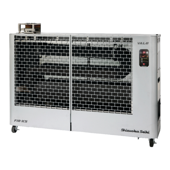
Page 2: Names Of Components
【Names of Components】 1 Combustion chamber 16 Solenoid valve 30 Off-timer display lamp 2 Radiation tube 17 Solenoid valve 31 Down button 3 Guard 18 Flame monitor 32 Up button 4 Operation panel 19 Draft tube 33 Conbustion level lamp 5 Exhaust port 20 igniter 34 Mode switching button... -
Page 3: Safety Devices
【Safety Devices】 Safety Devices Detecting condition Working condition after detecting The error code「A1」is displayed and the fan cools down the heater for Flame detection(Misfire) When the heater cannot detect a ignition during operation. about 5 minutes ( hereafter refferd to as Post-purge). When the heater detects a out of fuel at the beginning The error code「A2」is displayed . -
Page 4: Sequence Time Chart
【Sequence Time Chart】 PLUG SWITCH SWITCH Operation Switch Fan Motor Igniter Fuel Pump Solenoid Valve Flame Monitor Fuel pre-heater 10sec 50sec 300sec 15sec 2sec 5sec Post purge Ignition a: Ignition delay timer d: Post ignition b: Pump delay timer e: Stable time c:... -
Page 5: 6. Specifications
【Specifications】 Specifications Model Type VAL6 FIR-X5 Type Radiated / Direct-fired Ignition System High intensity discharge Fuel Kerosene or Fuel-Oil no heavier than No.2(Diesel) Level 5 : 0.53 GAL/h, 1.72 kg/h (75,100 BTU, 22.0 kW) Level 4 : 0.50 GAL/h, 1.63 kg/h (71,300 BTU, 20.9 kW) Fuel Consumption Level 3 : 0.48 GAL/h, 1.55 kg/h (67,600 BTU, 19.8 kW) - Page 6 【Troubleshooting】 Contents № Phenomenon Page Fuse blows out The heater does not start The heater does not ignition Misfire within 40 seconds after ignition Combustion stop during the operation Smell of fuel comes out Smoke comes out Fuel leaks Display「LV」 Noise occurs Combustion is not stable...
- Page 7 Phenomenon How to check Result Cause Remedy Fuse blows out. Disconnect all connectors from the burner controller, Fuse blows out Failure of burner controller Replace burner controller then plug the power cable into an outlet A. When the plug is put into an outlet. 0Ω...
- Page 8 Phenomenon How to check Result Cause Remedy The heater does not start. It works normally Replug power cable(CN1), and then turn on Disconnection of power cable Plug connector (CN1) firmly (Lamps is lit) A. The lamp does not light on. Measure voltage at (CN1) terminal burner controller AC 0V...
- Page 9 Phenomenon How to check Result Cause Remedy The heater does not start. Replug overheat protection connector (CN 11) , and Disconnection of overheat 「A3」is not displayed Plug connector (CN11) firmly then turn on (A ambient temperature is displayed) protection connector. D.
- Page 10 Phenomenon How to check Result Cause Remedy Stop of operation due to light Check if there is a hole in the combustion section part Display「A1」 There is a hole Replace combustion chamber leakage detection The valves does not change or it is A.
- Page 11 Phenomenon How to check Result Cause Remedy Misfire within 40 seconds after Lock of light quantity to flame Check dirty of flame monitor lens ⇒ Figure11(P.21) ignition. lens of flame monitor is dirty Clean flame monitor lens monitor Plug connector (CN 9) firmly Replug in the flame monitor connector (CN 9) , and Disconnection of flame 「A1」is not displayed...
- Page 12 Phenomenon How to check Result Cause Remedy 6 Smell of fuel comes out. Check air inlet opening of fan moter Air inlet opening is unusual Operate with appropriate air inlet opening Improper quantity of combustion air standard: 3.0 ⇒ Figure 13 (P.22) Check if the pipe is clogged Fuel line is clogged Flow rate is lower by clogged...
- Page 13 Phenomenon How to check Result Cause Remedy Noise occurs. Check air inlet opening of fan moter. Air inlet opening is unusual Operate with appropriate air inlet opening Improper quantity of combustion air Noise occurs. standard: 3.0 ⇒ Figure 13 (P.22) Check the marking of the nozzle Marking is incorrect Incorrect nozzle.
-
Page 14: Standard Resistance & Voltage
【Standard resistance & Voltage】 <Standard resistance of functional parts> Parts Connector No Lead Condition Resistance Memo 0Ω CN17 Operating Switch Red-Red 1-2PIN ∞Ω not in working 0Ω CN11 Tip-over Switch Black-Black 1-2PIN in working ∞Ω not in working 0Ω CN11 Overheat Protection Red-Red 3-4PIN... -
Page 15: Check & Repair
【Check & Repair】 Figure1 P.16 Removing a burner cover Figure2 Removing a burner unit P.16 Figure3 P.17 Mesuring resistance Figure4 P.17 Mesuring voltage Figure5 P.18 Checking a surge absorber (SA1) Figure6 P.18 Replacing a fuse Figure7 P.19 Checking a filter element Figure8 Checking a fuel tank P.19... - Page 16 Figure1 Removing a burner cover Loosen five screws and take the burner cover off. Burner cover Screw Figure2 Removing a burner unit 仕様・・・・・・・・・・・・・・・・・・・・ 修理マニュアル・・・・・・・・・・・・・・・ 参考資料(機能部品の基準抵抗)・・・・・・・ 点検・修理方法図・・・・・・・・・・・・・・ サーモモードランプ Disconnect the 4 connectors from the burner controller. ① (① Overheat prevention & Tip-over switch, ② Fuel sensor, ③ Operation board connector, ④Temperature sensor : refer to Wiring diagram(P.4)
- Page 17 ② Remove the flare nut, high nut, hose, external thermostast cord and power code. Figure3 Figure4 Mesuring resistance Mesuring voltage Operate the heater. ① Make sure the power cord is disconnected. ① Unplug an intended connector from Turn on the multimeter and set AC ②...
- Page 18 Figure5 Checking a surge absorber (SA1) Take out the operation board, and then point the lead head at solder part of SA1 Figure6 Replacing a fuse 1.Loosen five screws of burner cover and then take the cover cover off. 2.Take out the fuse from the fuse holder. 3.Replace with a new one.
- Page 19 Figure7 Checking a filter element 1. Remove the suction pipe from the fuel tank. 2. If the filter is dirty, replace it with a new one. 3. Return the suction pipe to the fuel and firmly secure. Figure8 Checking a fuel tank ①...
- Page 20 Figure9 Checking a fuel pump Take out a fuel outlet line then check whether or not fuel comes out. Please be careful because the fuel strongly comes out. Fuel outlet Figure10 Positioning a electrode ・Take out a burner and check each clearance as below. 2.3±0.2 inch 5.9±0.5 mm...
- Page 21 Figure11 Cleaning a flame monitor ① Unscrew five screws of burner cover and take ① Unscrew five screws of burner cover and take the burner coveroff. Pull out the flamemonitor and the burner coveroff. Pull out the flamemonitor and check whether or not its lens is dirty/foul check whether or not its lens is dirty/foul If the lens is dirty/foul, clean the surface of the ②...
- Page 22 Figure13 Adjusting an air inlet opening of fan motor standard:3 Loosen a screw and then extend/narrow an air inlet opening. Also trial operation is required after each adjustment. Be sure to repeat adjustment until following symptoms are identified. ・Black smoke is not coming out. ・White smoke extinguishes within a few seconds after ignition.
- Page 23 Figure15 Checking a burner packing Take out the burner cover and unit from main body, as detailed in Figure 1 and 2 . Check if there are「Burner packing 1」and「Burner packing 2」. Check if「Burner packing 1」and「Burner packing 2」are not damaged. Burner packing 1 (Thickness : 5inch) Burner packing 2 (Thickness : 20inch)
Need help?
Do you have a question about the FIR-X5 and is the answer not in the manual?
Questions and answers