
Summary of Contents for Metretek MTEK6000 Series
- Page 1 MTEK6000 SERIES USER'S MANUAL MTEK6000 SERIES Electronic Flow Corrector & Monitoring Devices Installation and Operating Instructions January 2002 Part # 900315 January 2002...
-
Page 2: Table Of Contents
Mounting the Instrument on the Meter ... Setting Up the Index Assembly ... Unit and Index Rotation ...…… . Counter Masking ………………………………………………………………… Pulse Input to the MTEK6000...… Wall and Pipe Mounting ...……... Transducers in the MTEK6000 ... Connecting the Pressure Tubing ... - Page 3 Calibrating the Temperature Transducer ... 3-11 Calibrating the Differential Pressure Transducer ... 3-12 Section 4: Optional Equipment Analog Output …………... MTEK6000 Analog Output Specifications …... 4-3 Installing the Analog Output Loop …... Calibrating the Analog Output …...…... Section 5: Maintenance and Software Packages Enclosure Maintenance ...
- Page 4 Figure 1-1, MTEK6000 Exterior View ....... . Figure 1-2, MTEK6000 Interior View ....... .
- Page 5 MTEK6000 SERIES USER'S MANUAL Metretek, Inc. is a registered trademark and MTEK6000, MTEKManager, pcGas, Meter Reader, Customer Monitor, AutoPoll, Label Changer, Site I.D. Changer, Units Changer and Virtual Keypad are trademarks of Metretek, Inc. All other trademarks are the property of organizations not connected with Metretek, Inc. and are used for reference purposes only.
- Page 6 MTEK6000 SERIES USER'S MANUAL January 2002...
-
Page 7: Chapter 1: Overview
Low-power CMOS design and sophisticated power conservation circuitry allow the MTEK6000 to operate one to two years on battery power. Two pulse inputs, two status inputs, two pulse outputs, two external analog inputs (4-20 mA or 1-5V) and a tamper input are standard. -
Page 8: Compliance
Substitution of components may impair suitability for Class 1, Division 1 and Class 1 Division 2 applications. COMPLIANCE The MTEK6000 device complies with Part 15 and Part 68 of the FCC Rule. See Appendix E for details. ONE-YEAR WARRANTY Metretek, Inc. warrants the products it... -
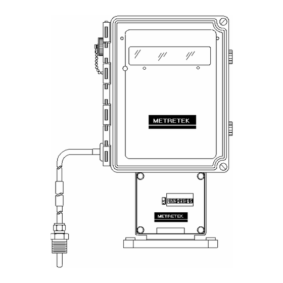
Page 9: Figure 1-1, Mtek6000 Exterior View
MTEK6000 SERIES USER'S MANUAL Figure 1-1 MTEK6000 exterior view January 2002 1 - 3... - Page 10 MTEK6000 SERIES USER'S MANUAL Figure 1-2 MTEK6000 interior view 1 - 4 January 2002...
-
Page 11: Chapter 2: Installation
1. Thoroughly examine the box to verify it was not damaged in shipping. If you find damage, immediately file a claim with the shipper. 2. Carefully unpack the MTEK6000 from the shipping container. Verify that the box contains every item listed on the shipping order. -
Page 12: Power For The Mtek6000
(~ 1yr life) or as a pair. MTEK6000 SERIES USER'S MANUAL B. MTEK6000 UPS power supply - an un- interruptible 12 VDC power supply with battery back up. C. SPS 50 solar system - 10 to 64 W systems available with battery backup;... -
Page 13: Setting Up The Index Assembly
4. Take care to align the gears properly, and verify that they turn freely and do not bind. When changing a MTEK6000 in the field from a 10, 100, 1,000 or 10,000 ft meter with a 5 ft /rev drive, the CF per Pulse... -
Page 14: Unit And Index Rotation
In general, the label side of the index base plate (front) should face the front of the meter. This allows the MTEK6000 EFC to also face the front of the meter. In certain applications, the MTEK6000 EFC and index can be... -
Page 15: Pulse Input To The Mtek6000
See Appendix A for These pulses addressing. WALL AND PIPE MOUNTING The MTEK6000 can also mount directly on a wall or on a pipe. Mounting feet are provided switch for wall mounting. See Figure 2-5. For pipe mounting, approximately 10 feet of 2-inch rigid iron pipe or conduit is required. -
Page 16: Figure 2-5, Wall Mounting
MTEK6000 SERIES USER'S MANUAL Figure 2- 5 Wall Mounting Figure 2- 3 Wall Mounting Figure 2- 4 Pipe Mounting January 2002... -
Page 17: Transducers In The Mtek6000
TRANSDUCERS IN THE MTEK6000 The MTEK6000 uses a precision strain gauge pressure transducer mounted inside the unit, combining maximum accuracy with low power consumption. temperature, the MTEK6000 employs a highly linear and stable device, a platinum resistive temperature detector (RTD). Case... - Page 18 MTEK6000 SERIES USER'S MANUAL Figure 2- 7 Typical Installation for MTEK6000 EFC Figure 2- 6 Typical Installation for MTEK6000 EFM January 2002...
-
Page 19: Installing The Thermal (Temperature) Probe
INSTALLING THE THERMAL PROBE A thermal (temperature) probe is connected to the MTEK6000 by a 6-foot (2-meter) cable. You should coil excess cable to prevent possible damage. designed to fit into standard Metretek, Inc. thermowells. Optional 15-foot (4.5 meter) and 30-foot (9-meter) cables are available. -
Page 20: Installing The Pulse Output Wiring
INSTALLING THE PULSE OUTPUT WIRING The MTEK6000 comes standard with a board installed that provides two optically isolated pulse outputs. These outputs are configurable as either Form C or Form A type outputs. An alternative version of the board is available that provides four pulse outputs. - Page 21 No configuration is necessary to enable the uncorrected mechanical pulse output. January 2002 MTEK6000 SERIES USER'S MANUAL Uncorrected Pulse Output Specifications 1. 3W contact rating (power dissipation). 2. Maximum switching voltage up to 30V. 3. Maximum switching current up to 200mA.
-
Page 22: Communications
Table 2-2 shows the diagnostic features of the Activity indicator when the cable is connected. WARNING The MTEK6000 will not go to sleep if the RS-232C serial cable is left connected and battery life will be affected drastically. 2-12 MTEK6000 SERIES USER'S MANUAL... -
Page 23: Table 2-2, Activity Indicator
MTEK6000 Function (RS232 cable connected) RS-232C cable connected Set #1 Pulse received Reset #1 Pulse received Set #2 Pulse received Reset #2 Pulse received RS-232C cable disconnected January 2002 MTEK6000 SERIES USER'S MANUAL Table 2-2 Activity Indicator 1 long blink... - Page 24 MTEK6000 SERIES USER'S MANUAL Figure 2- 10 Corrector Board connection and jumper configuration diagram 2-14 January 2002...
-
Page 25: Grounding
If the MTEK6000 is to be connected to a telephone line (either on-board or through a PLI mounted in a safe area) or connected to a... - Page 26 MTEK6000 SERIES USER'S MANUAL 2-16 January 2002...
-
Page 27: Chapter 3 : Operating Modes
MTEK6000 power-down in one minute after the operator stops interacting with it. NOTE The MTEK6000 will not go to sleep if the RS-232C serial cable is connected and battery life will be affected drastically. DISPLAY MODE In this mode, the display normally shows a two-character label and a value. -
Page 28: Alarm Mode
ALARM MODE The MTEK6000 can be configured to activate an alarm when certain conditions are met or when user defined limits are exceeded. You can display active alarm messages on the optional external keypad and display or alarm codes on the standard display. - Page 29 When this happens, the unit generates a Faulty Counter alarm (see the section on Pulse Input to the MTEK6000 in chapter 2 for more details). First Time Power Alarm First Time Power alarm is defined as the re- application of power after interruption of the power source.
- Page 30 MTEK6000 SERIES USER'S MANUAL Lost Pressure Alarm A Lost Pressure alarm is generated when the pressure circuitry is over-ranged. This...
-
Page 31: Memory (History Logging)
If there is a fault in the software, the Software Error alarm will initiate. MEMORY (HISTORY LOGGING) The MTEK6000 has a total of 96K (Main 64K bank and Auxiliary 32K bank) of RAM for database, audit trail, and history logging. -
Page 32: Configuration Mode
To enter configuration mode, press conf. If configuration mode is password protected, the MTEK6000 will display ENTER PASSWORD?. Only a valid password entry would then be given access to this mode. -
Page 33: Figure 3-1, Optional Keypad And Display
MTEK6000 SERIES USER'S MANUAL Figure 3 - 1 Optional Keypad and Display January 2002 3 -7... -
Page 34: Assigning Function Keys
To assign a first be uploaded and reset by the host software. Wake-Up on Pulse (Event Driven) The MTEK6000 EFC employs a wake-up on pulse (event driven wake-up) mode in which the unit can be configured to wake-up on a specified revolutions). -
Page 35: Special Key Combinations
There are a number of special key combinations that allow the user to view system information and perform certain tasks very easily. They are: F0 and span Displays the MTEK6000 run (calculation) time. The unit must wake-up by itself at least once before a correct reading is displayed. -
Page 36: Calibration Mode
While operating in the calibration mode, the MTEK6000 continues to store pulses and periodically updates volume, pressure, and temperature data using the values measured when calibration mode was initially entered. -
Page 37: Calibrating The Temperature Transducer
5. Press zero. The display now shows: January 2002 MTEK6000 SERIES USER'S MANUAL ZERO> NEW?> XX.XXX represents the unit's default zero value. If the current zero reference matches the unit's default, simply press ent to collect the new point. -
Page 38: Calibrating The Differential Pressure Transducer
8. Apply the span (full scale) reference to 3-12 MTEK6000 SERIES USER'S MANUAL the differential pressure sensor and wait for the reading to stabilize 9. Press span. The unit now shows: SPAN>... -
Page 39: Chapter 4: Optional Equipment
4-20mA output for flow rate, pressure, or numerous other control and monitoring applications. Up to two modules can be installed in the MTEK6000 in place of the batteries by using the AO module adapter plate, (Metretek stk #1008-0011B- 001). -
Page 40: Figure 4-1, Analog Output Option
MTEK6000 SERIES USER'S MANUAL Figure 4 - 1 Analog Output Option 4 - 2 January 2002... -
Page 41: Mtek6000 Analog Output Specifications
4-20mA signal is being sent. Calibrating the Analog Output Several features make the Analog Output software calibration routine attractive and more intuitive. In the MTEK6000 device, unit calibration can be software-based; there need laborious adjustments. Software calibration does... - Page 42 20.0 +y.yyy mA 4 - 4 MTEK6000 SERIES USER'S MANUAL x.xxx represents the default span value (full scale) and y.yyy is the adjustment made to 20mA for the analog output signal. The adjustment can either be positive or negative shown by + or - respectively.
-
Page 43: Chapter 5 : Maintenance And Software Packages
Excess moisture can ruin an MTEK6000 if allowed to accumulate within the enclosure. Although the circuit boards themselves are conformal coated to protect... -
Page 44: Pcgas Meter Reader
Site I.D. stored in the device. 5 - 2 MTEK6000 SERIES USER'S MANUAL Label Changer - View and change label and function key definitions. Virtual Keypad - keypad in the MTEK6000 products. Can used configuration calibration. pcGas Customer Monitor pcGas Customer Monitor lets personnel responsible collecting conveniently interact with the unit. -
Page 45: Dc2000
MTEK6000 SERIES USER'S MANUAL DC2000 The MTEK6000 is fully compatible with Metretek’s DC2000. DC2000 is Metretek’s flagship collection and management software system for energy data. DC2000’s scaleability and flexibility enables users to choose from a wide range of functions and data throughput configurations. - Page 46 MTEK6000 SERIES USER'S MANUAL 5 - 4 January 2002...
-
Page 47: Appendix A: Process Configuration Standard
APPENDIX A: PROCESS CONFIGURATION STANDARD The MTEK6000 uses Process configuration for database organization and management. Table A-1: Standard display mode and function keys for MTEK6000 EFC Label I.D. Description F1 1 CV Corr Volume MCF 051102 F2 2 UV Uncor Volume MCF 051108... - Page 48 Low Aux Press Lost Aux Press MTEK6000 SERIES USER'S MANUAL Table A-6: Standard history data stored in the MTEK6000 EFC w/ Aux Pressure 40 days of daily corrected volume Address 40 days of daily uncorrected volume 40 days of daily maximum flow rate...
- Page 49 Table A-7: Standard display mode and function keys for MTEK6000 EFC w/2 Aux Pressure Label I.D. Description F1 1 CV Corr Volume MCF 051102 F2 2 UV Uncor Volume MCF 051108 F3 3 PR PRessure PSG F4 4 FT Flow Temp deg F...
- Page 50 Table A-9: Standard history data stored in the MTEK6000 EFC w/ 2 Aux Pressure 40 days of daily corrected volume 40 days of daily uncorrected volume 40 days of daily maximum flow rate 40 days of daily minimum flow rate...
- Page 51 Switch 1 Alarm Switch 2 Alarm January 2002 MTEK6000 SERIES USER'S MANUAL Table A-12: Standard history data stored in the MTEK6000 EFC2 w/ 2 Aux Press 40 days of daily corrected volume 1 210401 40 days of daily corrected volume 2...
- Page 52 High Aux Press Low Aux Press Lost Aux Press Table A-15: Standard history data stored in the MTEK6000 EFM w/ Aux Pressure 40 days of daily corrected volume 40 days of daily average temperature 40 days of daily maximum flow rate...
- Page 53 Table A-16: Standard display mode and function keys for MTEK6000 EPR Label I.D. Description F1 1 P1 Pressure #1 2 PS Pressure Scale 3 HI High press In al 4 HO High press Out al 5 LI Low press In al...
- Page 54 LowVolt Shutdown Open Door Software Error MTEK6000 SERIES USER'S MANUAL Table A-21: Standard history data stored in the MTEK6000 ETR Address 40 days of daily average temperature 40 days of daily maximum temperature 020304 40 days of daily minimum temperature...
- Page 55 Open Door 140706 Software Error 020309 020302 Table A-24: Standard history data 220302 stored in the MTEK6000 EPTR 220402 220403 40 days of daily average pressure 230302 40 days of daily maximum pressure 230402 40 days of daily minimum pressure...
- Page 56 MTEK6000 SERIES USER'S MANUAL A-10 January 2002...
-
Page 57: Appendix B: Calculations
APPENDIX B: CALCULATIONS AGA-7 Volume Calculations The MTEK6000 EFC performs volume calculations based on the Ideal Gas Law. Boyle’s Law is used for pressure and Charles’s Law for temperature. These laws state that the volume of any definite weight of... - Page 58 MTEK6000 SERIES USER'S MANUAL B -2 January 2000...
-
Page 59: Appendix C: Parameter Description
APPENDIX C: PARAMETER DESCRIPTION The parameters relative to the operation and configuration of the MTEK6000 are listed below (See Appendix A for the addresses of these parameters). Alarm Pulse Output Enable/Disable The EFC can generate a generic pulse output on any alarm condition. - Page 60 35.8. Enter -1 to disable. The Default value is -1. C - 2 MTEK6000 SERIES USER'S MANUAL Corrected Volume The corrected volume is calculated based upon AGA report #7 or #8 and reflects the corrected volumetric flow taking the base conditions into consideration.
- Page 61 The Default value is 100,000. January 2002 MTEK6000 SERIES USER'S MANUAL Date (Month, Day, Year) This is the current Date in the unit (MMDDYY). It is updated on each process scan. Flow Rate Update Interval (s) This parameter determines how often the flow rate gets updated in the EFC.
- Page 62 The setpoint at which the unit determines that there is a High Pressure alarm condition. The Default value is 1500. C - 4 MTEK6000 SERIES USER'S MANUAL High Pressure Alarm Reset After a High Pressure alarm occurs, the setpoint at which the unit exits this condition is entered in this location.
- Page 63 If the content is unknown, a zero (0) should be entered. The Range is 0 to 0.15 (15%). The Default is 0. January 2002 MTEK6000 SERIES USER'S MANUAL Percent N2 This parameter reflects the content of nitrogen (N2) currently present in the gas.
- Page 64 The Default value is 0. C - 6 MTEK6000 SERIES USER'S MANUAL Uncorrected Volume & Flow Multiplier This multiplier specifies the output value for uncorrected volume and flow. For example,...
- Page 65 Units of Measure The MTEK6000 can be configured to calculate volume and flow with English or Metric units. The database ca be setup for the following units of measure: Flow & Volume...
- Page 66 MTEK6000 SERIES USER'S MANUAL C - 8 January 2002...
-
Page 67: Appendix D : Board Jumper Positions
MTEK6000 SERIES USER'S MANUAL APPENDIX D : BOARD JUMPER POSITIONS 61-SBC Revision A – Corrector Board January 2002... - Page 68 JP5 can be used as a convenient means to connect pulse input 2 as follows: Description connect pulse input 2 to mechanical index secondary output otherwise MTEK6000 SERIES USER'S MANUAL Jumper position JP5 A, B, & C all in JP 5 A, B, & C all out (default) January 2002...
- Page 69 Status / Pulse Input #3: Use Terminal 26 (set input) Terminal 27 (ground) Terminal 28 (reset input) External Access to the Mechanical Index: (separate form C contacts) January 2002 MTEK6000 SERIES USER'S MANUAL Jumper position JP6 = A JP6 = B JP6 = C Terminal 25 (normally open)
- Page 70 MTEK6000 SERIES USER'S MANUAL 50-PLI Revision C - Phone Line Interface J1: Connections from the PLI to the Corrector board J3: Telephone line connection J4: Earth Ground (for surge suppression) connection JP5: position 2-3 shorts R9 sometimes required when barriers cause too much drop in the OH signal level (default position is 1-2).
-
Page 71: Consumer Information And Fcc Requirements
In most areas, the sum of the RENs of all devices on any line should not exceed five (5.0). If too January 2002 MTEK6000 SERIES USER'S MANUAL many devices are attached, they may not ring properly. Service Requirement 5. -
Page 72: Warranty And Repair Service
To be supplied when final Class 1, Div 1 & Div 2 approvals for this unit are received MTEK6000 SERIES USER'S MANUAL NOTICE The Ringer Equivalence Number (REN) assigned to each terminal device provides an... - Page 73 MTEK6000 SERIES USER'S MANUAL EL0001 (Sheet 1 of 2) : Class I Division 2 Installation January 2002...
- Page 74 MTEK6000 SERIES USER'S MANUAL EL0001 (Sheet 2 of 2) : Class I Division 2 Installation January 2002...
-
Page 75: Appendix F : Warranty Information
January 2002 MTEK6000 SERIES USER'S MANUAL The seller makes no representation or warranty other than those set forth in this agreement. THE WARRANTY STATED HEREIN IS EXPRESSLY IN LIEU OF... - Page 76 MTEK6000 SERIES USER'S MANUAL January 2002...
- Page 77 MTEK6000 SERIES USER'S MANUAL APPENDIX G: TII Station Protector January 2002...
- Page 78 MTEK6000 SERIES USER'S MANUAL January 2002...
-
Page 79: Appendix H: Hazardous Area Installation Control Drawings
MTEK6000 SERIES USER'S MANUAL APPENDIX H: Hazardous Area Installation Control Drawings October 2002... - Page 80 MTEK6000 SERIES USER'S MANUAL October 2002...
- Page 81 MTEK6000 SERIES USER'S MANUAL October 2002...
Need help?
Do you have a question about the MTEK6000 Series and is the answer not in the manual?
Questions and answers