Table of Contents
Advertisement
Quick Links
Advertisement
Table of Contents

Related Manuals for allfi 919115

Summary of Contents for allfi 919115
- Page 1 Operating and maintenance instruction Shut-off valve 2.0 (4150 bar / 60,000 psi) Operating and maintenance instruction ALLFI AG - Riedenmatt 1 – CH-6370 Stans Tel.: +41 41 618 05 05 - Fax: +41 41 618 05 10 E-Mail: info@allfi.com - http://www.allfi.com...
- Page 2 General Scope of application The present operating and maintenance instruction is valid for: Shut-off valve 3/8" 2.0 (4150 bar / 60,000 psi) 919115 919116 UH-919115 2 / 20 Shut-off valve 2.0 (4150 bar / 60,000 psi) 09.01.2023...
-
Page 3: Table Of Contents
General Table of contents General ............................4 Information on use of the operation and maintenance instruction ........4 Scope of delivery .........................4 Warranty claim ........................4 Disclaimer..........................4 Security ............................5 Declaration of symbols ......................5 General warning notes ......................5 Intended use ........................6 Inadmissible usage ......................7 Residual risks ........................7 Safety installations ......................8 Personal protection equipment ...................8... -
Page 4: General
Valve Case 1.4 Disclaimer ALLFI AG refuses any claims of liability (material damages, physical injury, as well as disruption of op- eration), that are a result of disregarding this operating and maintenance instruction. For example, the damage as a consequence of: ... -
Page 5: Security
Security 2 Security 2.1 Declaration of symbols This operating and maintenance instruction manual contains important notes and symbols, which are to be considered and followed. These include: DANGER Danger emphasizes operating and service procedures that if not avoided, may lead to death or serious personal injuries. WARNING ... -
Page 6: Intended Use
Security DANGER Danger of cutting of extremities on contact with waterjet The contact with the high kinetic energy performing waterjet can have the conse- quence of cutting of extremities or lead to other injuries. Therefore: Operate the machine only, when nobody stands in the danger zone of the waterjet. -
Page 7: Inadmissible Usage
ALLFI AG - Riedenmatt 1 – CH-6370 Stans Tel.: +41 41 618 05 05 - Fax: +41 41 618 05 10 E-Mail: info@allfi.com - http://www.allfi.com... -
Page 8: Safety Installations
Security 2.6 Safety installations The manufacturer or the operator of the full machine, which the shut-off valve is built in, has ensured the following safety arrangements: Safety devices to prevent flying fragments or liquids leaking under high pressure Emergency stoppage to immediately shut down the operating machine ... -
Page 9: Structure And Function
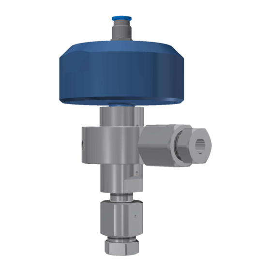
Structure and function 3 Structure and function 3.1 Structure 1. Pneumatic Cylinder 2.0 2. Seal Kit 2.0 2.1. Valve needle 2.2. Pressure plate 2.0 2.3. HP-seal 2.0 2.4. Compression Spring 3. Coupling Ring 4. Valve Seat 5. Adapter 3/8" to Valve Case 6. -
Page 10: General Technical Data
General technical data Article: Torque wrench Open end fitting Mounting tool for O-ring Article no: 000468 AF 17 – 000339 040011 AF 22 – 000272 AF 24 – 000280 AF 27 – 000511 Function: Tightens screws with a O-ring assembly and dis- specific torque assembly All accessories for metric cutting heads are included in case set 882101... -
Page 11: Installation And Commissioning
Installation and commissioning Technical data as dimensions can be found in the technical drawing in appendix A. 5 Installation and commissioning General installation tip: Use of a pneumatic oiler is forbidden. Compressed air filter with water separator must be installed. ... -
Page 12: Fix Cutting Head To The Machine
Installation and commissioning NOTE Material damage as a result of pitting Not or insufficient greased threads or contact areas can pit. Therefore: Always grease threads and metallic contact areas. Check appendix A for addi- tional information. NOTE ... - Page 13 Installation and commissioning Unscrew the gland nut from the coupling ring. Remove collar from gland nut. Slide the gland nut over the HP tube. Screw the collar on the HP tube (left-handed thread). There must be 1 or 2 convo- lutions visible between the conus and the pressure ring.
-
Page 14: Function Check Of The Shut-Off Valve
Deinstallation Connect the HP tube with the shut-off valve torque see appendix A. Plug in compressed air con- nection by snapping in. 5.2 Function check of the shut-off valve Close and open the shut-off valve several times under operating conditions (water pressure = operat- ing pressure). -
Page 15: Maintenance, Service And Repair
Maintenance, Service and Repair 7 Maintenance, Service and Repair Before uninstalling the shut-off valve, release pressure from the HP tube and protect against unexpected re-pressurizing. The shut-off valve must be removed from the machine for maintenance, servicing and repair work ac- cording to chapter 6. -
Page 16: Reversing (Turning) The Valve Seat
Maintenance, Service and Repair 7.2 Reversing (turning) the valve seat Reason: Valve seat leaking 1. Removing the shut-off valve from the machine is recommended (Chapter 6) 2. Screw adapter out of valve case Attention! Counter hold the valve case AF 24 1. -
Page 17: Replace Seal Kit And Valve Seat
Maintenance, Service and Repair 7.3 Replace seal kit and valve seat Reason: High pressure seal leaking 1. Removing the shut-off valve from the machine is recom- mended (Chapter 6) 2. Screw adapter out of valve case Attention! Counter hold the valve case AF 24 1. - Page 18 Maintenance, Service and Repair Grease the outer cone and the pressure surface of the support disc of the new seal kit according to Appendix A. 2. Place the new seal kit on the pneumatic cylinder. 1. Grease the thread of the cylinder ac- cording to appendix A.
-
Page 19: Faults And Troubleshooting
Faults and Troubleshooting 8 Faults and Troubleshooting Before uninstalling the shut-off valve, release pressure from the HP tube and compressed air tube. Protect against unexpected re-pressurizing. NOTE Material damage as a result of leakages Constant leakage may damage the product. Therefore: Immediately eliminate leakages. -
Page 20: Further Troubleshooting
Recycling Pos. of the leak- Cause of the leakage Action Chapter HP-Sealing damaged Replace seal kit Seal cone in valve case or Replace damaged parts Seal kit Pressure platedamaged (Check twice if the Wrong torque for the pneu- Use correct torque according ap- leakage is not at po- matic cylinder pendix A...
Need help?
Do you have a question about the 919115 and is the answer not in the manual?
Questions and answers