
Summary of Contents for delta-mobrey MSM400
- Page 1 Reference Manual IP258, Rev. C Jan 2023 Mobrey MSM400 Sludge Density Monitor With a Standard Range 1 MHz / 3.3 MHz Ultrasonic Sensor...
- Page 3 For information on nuclear-qualified products, contact an Delta Mobrey Sales Representative. Replacement equipment or spare parts not approved by Delta Mobrey for use as spare parts could reduce the capabilities of the Mobrey MSM400, and may render the instrument dangerous.
-
Page 5: Table Of Contents
Before you install ..............12 3.2.1 Preliminary checks ............12 3.2.2 General considerations ............ 12 Mounting the Mobrey MSM400 control unit ........13 Installing the gap sensors ............14 3.4.1 Installation: Mobrey 433 tank mounted gap sensor ......14 3.4.2 Installation: Mobrey 448 pipe-section gap sensor ...... - Page 6 Current output and HART connections ........23 Section 4: Getting Started Safety messages ..............31 Switching on the power ............32 4.2.1 Switching on the Mobrey MSM400 ......... 32 The menu system ..............32 4.3.1 How to navigate the menu system ..........32 4.3.2 How to change settings on parameter screens ......
- Page 7 Reference Manual Table of Contents IP258, Rev. C Jan 2023 5.2.3 Fault messages .............. 62 5.2.4 Other messages ............. 63 Servicing ................63 Restoring the factory defaults ............ 64 5.4.1 Restore factory default settings ..........64 Tests ................. 64 5.5.1 Simulation (auto cycle) ............
- Page 8 Table of Contents Reference Manual Jan 2023 IP258, Rev. C European directive information ..........78 Hazardous locations certification ............79 B.4.1 Control unit approvals ............. 79 B.4.2 Gap sensor approvals ............79 B.4.3 Instructions for hazardous area installation ......... 80 Appendix C: Menu Maps and Parameters Safety messages ..............
- Page 9 Failure to follow these installation guidelines could result in death or serious injury: The Mobrey MSM400 Sludge Density Monitor must be installed, connected, ◼ commissioned, operated, and maintained by suitably qualified personnel only, observing any national and local requirements that may apply Use the equipment only as specified in this manual.
-
Page 10: Section 1: Introduction
IP258, Rev. C Jan 2023 Manual overview This manual provides installation, configuration and maintenance information for the Mobrey MSM400 with a standard range 1 MHz / 3.3 MHz ultrasonic sensor. Section 2: Overview Section 3: Installation Section 4: Getting Started... -
Page 11: Section 2: Overview
Failure to follow these installation guidelines could result in death or serious injury: The Mobrey MSM400 Sludge Density Monitor must be installed, connected, ◼ commissioned, operated, and maintained by suitably qualified personnel only, observing any national and local requirements that may apply Use the equipment only as specified in this manual. -
Page 12: The Mobrey Msm400 Sludge Density Monitor
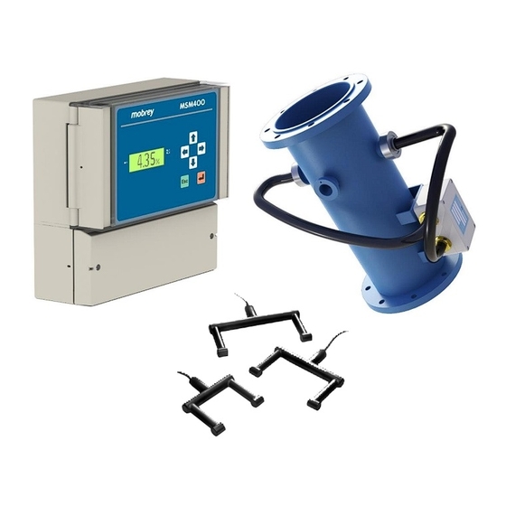
(Figure 2-1 on page The MSM400 operates with a Mobrey 448 gap sensor, that comes as a complete pipe section, or a Mobrey 433 gap sensor suspended in an open tank. The sensors measure the suspended solids concentration in the liquid (gap) between two opposite sensor faces. -
Page 13: Measurement Principle
Zero In the Mobrey MSM400 control unit’s memory, there is Point information about various sludge types to enable a basic set-up. Adjustments to the set-up can be made %Solids after on-site samples have been taken. - Page 14 Section 2: Overview Reference Manual Jan 2023 IP258, Rev. C Section 2: Overview...
-
Page 15: Control Unit Features
433 tank-mounted sensor suspended in the sludge blanket. The relay output in the MSM400 can be used to stop the de-sludge cycle when the liquid runs clear, switching at typically a few percent suspended solids. -
Page 16: Control Unit Functions
– Relay RL1 operates at chosen values in density units. – Relay RL2 is a fault relay by default, which may be assigned to control duty if required. The MSM400 can be set-up to perform standard, water-industry de-sludging control. ◼... -
Page 17: Control Unit Front Panel
Reference Manual Section 2: Overview IP258, Rev. C Jan 2023 Control unit front panel This section describes the front panel fascia, which has an integral keypad and display. Note A full specification for the control unit is in Appendix A: Reference Data. -
Page 18: Display
Full Primary Display is presented. The default Full Primary Display features a digital clock, Primary Value (% Solids) with display units, bargraph representation of output current, and status icons. Figure 2-6. Typical Display Of The MSM400 4.35% A. Off-line/On-line Status (Locked Padlock = On-line) D. - Page 19 Reference Manual Section 2: Overview IP258, Rev. C Jan 2023 Section 2: Overview...
-
Page 21: Section 3: Installation
Failure to follow these installation guidelines could result in death or serious injury: The Mobrey MSM400 Sludge Density Monitor must be installed, connected, ◼ commissioned, operated, and maintained by suitably qualified personnel only, observing any national and local requirements that may apply Use the equipment only as specified in this manual. -
Page 22: Before You Install
3.2.1 Preliminary checks The Mobrey MSM400 Sludge Density Monitor is normally supplied in two packages: one for the control unit; and one for the pipe section or tank-mounted gap sensor. Take care in handling the heavy pipe section. In particular, do not damage the cable or the hose... -
Page 23: Mounting The Mobrey Msm400 Control Unit
Reference Manual Section 3: Installation IP258, Rev. C Jan 2023 Mounting the Mobrey MSM400 control unit Guidelines This housing is IP65-rated. It is suitable for mounting outside, but a protective weather ◼ shield is recommended. The wall-mounting should be above any flood level, away from any overflow path, and away from direct sunlight. -
Page 24: Installing The Gap Sensors
Figure 3-1. Mobrey 433 Tank Mounted Gap Sensor Mobrey 433 Tank Mounted Gap Mobrey MSM400 Sensor The 433 sensor should be kept away from a wall to avoid any non-moving slurry or “dead” settlement areas. It is advisable to have an arrangement that allows removal of the sensor for periodic cleaning and ragging removal. -
Page 25: Installation: Mobrey 448 Pipe-Section Gap Sensor
The pipe section gap sensor is often mounted below ground-level or in confined spaces. ◼ Appropriate additional precautions must be taken when working in this environment. Figure 3-2. Mobrey 448 pipe-section gap sensor (vertical orientation) Mobrey MSM400 Note: Control Unit In this vertical orientation,... - Page 26 Section 3: Installation Reference Manual Jan 2023 IP258, Rev. C Pipe-section orientation Particular attention must be paid to the positioning of the pipe section in relation to pressure reduction or agitation of the sludge to be monitored. Figure 3-3. Sensor orientation for horizontal pipe line Not Okay –...
-
Page 27: Electrical Installation
Reference Manual Section 3: Installation IP258, Rev. C Jan 2023 Electrical installation 3.5.1 Control unit electrical connections All field wiring connections are accessible on the control unit by removing the lower terminal cover. Never remove or modify the mechanical barriers separating the terminal area from the main enclosure, and separating the transmitter input terminals from other terminals. - Page 28 Section 3: Installation Reference Manual Jan 2023 IP258, Rev. C Connection terminals Figure 3-4. Connection terminals layout B SCN 10 11 TRIGGER RELAY 1 RELAY 2 ISSUE 14 15 CURRENT OUT DC IN Note Not all of the labelled terminals are functional in this version of the control unit. ◼...
-
Page 29: Gap Sensor Connections And Cabling
Gap sensor connections and cabling Connection of a gap sensor to the MSM400 control unit does not confer intrinsic safety on the sensor. It is the responsibility of the installer to ensure any sensor installed in a hazardous area is suitable for use and certified accordingly. -
Page 30: Power Connections
SCN A Cable 2 3.5.3 Power connections The MSM400 control unit can be powered either by 24 Vdc or by 115/230 Vac mains alternating current (AC) power. When the control unit is mains powered (Figure 3-7 on page 21), use the voltage-selector slide switch to select 115 or 230 Vac as appropriate for the installation location. -
Page 31: Earthing Connections
◼ advisable. 3.5.4 Earthing connections The MSM400 must be earthed (grounded) using terminal 31 (Protective Earth). Terminals 3 and 4 are used for connecting the cable shields (screens) of the two, twisted-pair, sensor cables (see Figure 3-6 on page 20). This shield should be left unconnected at the sensor end unless there is a terminal for this purpose. -
Page 32: Relay Connections
Section 3: Installation Reference Manual Jan 2023 IP258, Rev. C 3.5.5 Relay connections There are two voltage-free contact relays. Connections for relays RL1 and RL2 are shown in Figure 3-9 on page 22. By default, each relay is in a de-energized (Normally Open) state. The present relay statuses are shown on the right-hand side of the Full Primary Display. -
Page 33: Digital Trigger Input Connections
To enable HART communications, the loop-resistance must be a minimum of 250 Ohms. The Current Output can drive a maximum loop-resistance of 1000 Ohms when internally powered. A selectable HART resistor (270 Ohms) is inside the MSM400 control unit. The default selection setting (PL1 in the left-hand position) does PL1 In not enable the internal HART resistor. - Page 34 Wireless THUM Adaptor Only (MSM400 is a HART master only) ......Figure 3-14 on page 26 Option 2b: Current Output, and Wired and Wireless HART .
- Page 35 Reference Manual Section 3: Installation IP258, Rev. C Jan 2023 Internally-powered current loop (No THUM adaptor) Figure 3-11. Option 1a: current output only PL1 In Left-Hand To DCS Position (or similar) CURRENT OUT REFER TO MANUAL Notes: 1. Only Terminals 16 and 18 required. 2.
- Page 36 1. Only HART Test Points A and B are required. 2. PL1 must be in the right-hand position. Internally-powered current loop with THUM adaptor Figure 3-14. Option 2a: wireless THUM adaptor only (MSM400 is a HART master only) YELLOW PL1 In...
- Page 37 Reference Manual Section 3: Installation IP258, Rev. C Jan 2023 Figure 3-15. Option 2b: current output, and wired and wireless HART DCS or similar BLACK PL1 In External Left-Hand YELLOW Resistor Position HART Test CURRENT OUT REFER TO MANUAL Notes: 1.
- Page 38 Section 3: Installation Reference Manual Jan 2023 IP258, Rev. C Externally-powered current loop (no THUM adaptor) Figure 3-17. Option 3a: current output only (no HART communications) External Supply DCS or PL1 In similar Left-Hand Position 16 17 CURRENT OUT REFER TO MANUAL Notes: 1.
- Page 39 Reference Manual Section 3: Installation IP258, Rev. C Jan 2023 Externally-powered current loop with THUM adaptor Figure 3-19. Option 4a: current output, and wired (TPA/TPB) and wireless HART Notes: 1. Terminals 13, 16, and 18 are required for External wireless HART and the Current Output. Supply 2.
- Page 40 Section 3: Installation Reference Manual Jan 2023 IP258, Rev. C Section 3: Installation...
-
Page 41: Safety Messages
Explosions could result in death or serious injury: Verify that the operating environment of the Mobrey MSM400 Sludge Density Monitor is consistent with the appropriate hazardous locations certifications. Failure to follow safe installation and servicing guidelines could result in death or serious injury: Make sure only qualified personnel perform the installation. -
Page 42: Switching On The Power
The default PV is the percentage-by-weight of suspended solids (%Solids). An invalid value is indicated if the sensor is not connected or in air. The Mobrey MSM400 control unit takes the input from a Mobrey 433 or Mobrey 448 gap sensor (see Figure 2-1 on page... - Page 43 Reference Manual Section 4: Getting Started IP258, Rev. C Jan 2023 Figure 4-1. How to enter the menu system 4.35% CALIBRATION Navigation of the menu system is achieved by using the ARROW buttons, the red (ENTER) button, and the Esc button. The Esc button returns you to the previous menu level, or to the Full Primary Display if you are at the MAIN MENU on the top level.
- Page 44 READINGS Dxxx DIAGNOSTICS A. Pressing the red (ENTER) button switches the operating mode of the MSM400. An opened-padlock indicates that the unit’s settings can be changed. B. Selecting this will bring up the menu for configuring the MSM400. C. Direct parameter access menu for quickly bringing-up parameter screens. See Appendix D for a guide to this feature.
-
Page 45: How To Change Settings On Parameter Screens
Reference Manual Section 4: Getting Started IP258, Rev. C Jan 2023 4.3.2 How to change settings on parameter screens To understand how to change parameter settings, such as entering the sensor gap dimension or choosing the sensor type from an option list, follow the two examples in this section. Example 1: Entering the sensor gap dimension (value) Navigate to the Sensor Gap menu option (Figure... - Page 46 Section 4: Getting Started Reference Manual Jan 2023 IP258, Rev. C Figure 4-6. Sensor gap parameter screen (View Mode) Sensor Gap P100 Esc=Quit =Edit Figure 4-7. Sensor gap parameter screen (Edit Mode) Sensor Gap P100 0000 mm Esc=Quit =Save Figure 4-8. New sensor gap saved Sensor Gap P100 Esc=Quit...
- Page 47 Reference Manual Section 4: Getting Started IP258, Rev. C Jan 2023 Example 2: Choosing the gap sensor type from a list Navigate to the Sensor Type parameter (as shown in Figure 4-9) and then press the red (ENTER) button. After entering this parameter screen, it is in View Mode (see Figure 4-10).
-
Page 48: Guidance To Configuring The Msm400
◼ 4.4.1 Before starting to configure Configuring for an application is achieved from the front panel of the MSM400, or using a PC running AMS Device Manager or a Field Communicator with the Mobrey MSM400 Device Descriptor (DD) added. Refer to “Electrical installation”... - Page 49 Press the red (ENTER) button to display the MAIN MENU. Press the DOWN-ARROW button repeatedly until SETUP is highlighted. Press the red (ENTER) button three times. How to configure the Mobrey MSM400 Sludge Density Monitor Put the control unit ‘off-line’ by opening the padlock icon (see page 40).
-
Page 50: Initial Setting-Up
The configuration settings can be changed, but the Isolated Current Output and Relays (RL1 and RL2) are frozen. Fault relays are de-energized. A closed padlock icon indicates that the MSM400 is operating in the ‘on-line’ mode. Most of the unit configuration settings cannot be changed. However, it prompts to go ‘off-line’ (and enter a security PIN if set) when attempting to change a setting. -
Page 51: System Settings
Cancel Password option is selected from the MAIN MENU screen. The Cancel Password menu option appears only after correctly entering the PIN. It disappears when selected, and makes the MSM400 secure and prompt for the PIN when needed. Note If the PIN number has been forgotten, contact us for assistance. -
Page 52: Sensor Input
4.5.4 Sensor input SENSOR INPUT Snsr Serial No The MSM400 control unit is used exclusively with ultrasonic Sensor Type gap sensors. These take the form of either a Mobrey 433 Sensor Damping tank mounted sensor or a Mobrey 448 pipe section sensor. -
Page 53: Calibration
IP258, Rev. C Jan 2023 Calibration Calibration results in the MSM400 operating at either Frequency A (1 MHz) or Frequency B (3.3 MHz). It is essential, and must be performed. There are two calibration methods: Auto Calibration (Autocal) – see below ◼... - Page 54 Section 4: Getting Started Reference Manual Jan 2023 IP258, Rev. C AUTOCAL: zero setting (Mobrey 448 pipe section sensor) Ensure the Mobrey MSM400 control unit is off-line (opened padlock). Mobrey 448 Pipe Section Flood the pipe section with clean mother liquor.
- Page 55 Reference Manual Section 4: Getting Started IP258, Rev. C Jan 2023 Follow the on-screen instructions. Observe the two displayed values, Sludge Samples Are confirming they are reasonably stable. Required Press the red (ENTER) button to save when satisfied with the values, or quit using the Esc button. The control unit prompts to perform another SETSPAN operation.
- Page 56 If the values are saved, take actual samples (at the same time as Step 5) and send them Section 4: Getting Started Reference Manual to a laboratory to confirm the %Solids. IP258, Rev. C Jan 2023 Section 4: Getting Started...
- Page 57 Reference Manual Section 4: Getting Started IP258, Rev. C Jan 2023 This has saved the additional signal loss (due to sludge) to the control unit's memory. Proceed to AUTOCAL lab values (both sensor types) below. Note These values can be viewed (and edited) at Span 1 @ FreqA (P130), etc. ◼...
-
Page 58: Manual Entry Control Unit Calibration
(see page 43). If this is not possible and values have been provided, then follow this procedure: Ensure the Mobrey MSM400 control unit is off-line (opened padlock). Navigate to Zero ref@FreqA (P120) (CALIBRATION / MANUAL ENTRY / ZERO REF /... - Page 59 Reference Manual Section 4: Getting Started IP258, Rev. C Jan 2023 Span method: step (a) entering span settings The easiest way to set the span is to follow the AUTOCAL/SETSPAN routine as previously explained (on page 44). If this is not possible and figures have been provided from some source, then proceed as below: Navigate to Span 1 @ FreqA (P130).
- Page 61 Reference Manual Section 4: Getting Started IP258, Rev. C Jan 2023 Options include: None (inactive), Primary (Municipal sludge), Secondary (Municipal sludge), China Clay (Kaolin), Bauxite, Metal Hydrox(ides), Water (treatment) Alum, Potable (water) sludge, Lime Slurry, Copper Tails (tailings). Each sludge type has a signal loss (attenuation) expressed as dB per %Solids per mm sensor gap.
-
Page 62: Setup Menu
(usually quite small) of the dry solids or the mother liquor. 4.7.2 De-sludge function Menu: SETUP / DUTY (Mode) / DESLUDGE The de-sludge menu allows the Mobrey MSM400 control DESLUDGE unit to perform simple de-sludging functions using a relay. Start On... - Page 63 Reference Manual Section 4: Getting Started IP258, Rev. C Jan 2023 P251 Stop On This specifies what function ends the de-sludge operation. Options include: “None” (default) ◼ “Time” – see Interval 1 (P254) and Interval 2 (P256) ◼ “PV < level” – Primary Value falls below the relay Off Point level ◼...
-
Page 64: Current Output
Menu: Up Range Value SETUP / OUTPUT / CURRENT OUTPUT Alarm Current Note The output current is frozen while the MSM400 control unit is in the off-line (opened ◼ padlock) operating mode. See “Operating modes” on page P400 Low Range Value (Default: 0.00) This is the Primary Variable (PV) value represented by a 4 mA output, or a 0 mA output if Current Span (P403) is set to 0–20 mA. - Page 65 Reference Manual Section 4: Getting Started IP258, Rev. C Jan 2023 Table 4-1. Current Saturation and Alarm Levels Current Output Linear Limit Alarm Alarm P402 Options Factory Maximum HIGH (Output Default Setting Minimum (mA) (mA) (mA) (mA) Current) for P402 High (21.0 mA) Hold 20.5...
-
Page 66: Relays
Menu: SETUP / OUTPUT / RELAY RELAY 2 There are two Single Pole, Double Throw (SPDT) relays. Note Relay states are frozen while the MSM400 control unit is in the off-line (opened padlock) ◼ operating mode. See “Operating modes” on page Relay 1 The Relay 1 (RL1) output is normally configured as a Set Point relay. - Page 67 Reference Manual Section 4: Getting Started IP258, Rev. C Jan 2023 “Alarm” duty ◼ While an alarm condition exists (see page 56), it can be indicated by a relay energizing and the Isolated Current Output forced to a mA level specified by the parameter Alarm Current (P402).
-
Page 68: Alarms
As RL1 Min On (P415), but specific to Relay 2 (RL2). 4.7.5 Alarms Menu: SETUP / OUTPUT / ALARM The Mobrey MSM400 control unit can detect the following alarm conditions: Current Output Saturated (see P541 below): ◼ ALARM This alarm happens if the PV is such that the output... -
Page 69: Faults
D830. 4.7.6 Faults Menu: SETUP / OUTPUT / FAULT FAULT Memory fault The Mobrey MSM400 control unit can detect the following CU Temp Fault fault conditions: Sensor Limits Control Unit Memory Fault (see P560 below): ◼... -
Page 70: Display
Section 4: Getting Started Reference Manual Jan 2023 IP258, Rev. C Memory Fault(Default: “Both”) P560 Memory faults include ROM checksum error, EEPROM signature error, EEPROM checksum error, and RAM test failure. Options for indicating this fault condition are “None” (not indicated), “Relay” (see “Relays”... - Page 71 Running time for relay RL1 if energized D822-RL2 time Running time for relay RL1 if energized D844-CU Temp Temperature of MSM400 D850-Atten@A Measured attenuation when gap sensor is operating at 1 MHz D851-Atten@B Measured attenuation when gap sensor is operating at 3.3 MHz D860- Freqncy.
-
Page 72: Engineering
P630 Sensor Frequency (Default: Auto) The MSM400 control unit may operate at one of two frequencies, A or B, which are 1 MHz or 3.3 MHz respectively. Sensor Frequency is used to determine the actual operating frequency that the MSM400 will use (D860). -
Page 73: Section 5: Service And Health Checks
Failure to follow these installation guidelines could result in death or serious injury: The Mobrey MSM400 Sludge Density Monitor must be installed, connected, ◼ commissioned, operated, and maintained by suitably qualified personnel only, observing any national and local requirements that may apply Use the equipment only as specified in this manual. -
Page 74: General Troubleshooting
Section 5: Service and Health Checks Reference Manual Jan 2023 IP258, Rev. C General troubleshooting 5.2.1 Troubleshooting guide There is no display Check if the power supply cable insulation is preventing contact at the terminal block ◼ Check if the correct power supply is connected to the correct terminals ◼... -
Page 75: Other Messages
Solvents or bleaches should not be used. Do not modify or repair the unit There are no spare parts for the MSM400. If a problem persists, contact us for advice. ◼ The contact details are on the back page of this reference manual... -
Page 76: Restoring The Factory Defaults
It is advisable to keep a record of settings, if possible. Tests This is a guide to tests, Current Output adjustments, live readings, and diagnostic data for the MSM400. Included is a summary of the fixed (permanent) data of the MSM400 e.g. the unit’s serial number. 5.5.1... -
Page 77: Display
The DISPLAY screen is for visually checking that are Esc=Quit =Start no dead LCD pixels. To start, press the red (ENTER) button. After completion of the visual test, the MSM400 model number and software version are displayed. Use the Esc button to exit to the menu system. 5.5.3... -
Page 78: Readings And Results
D805 % Current Output This is the continuously calculated theoretical percentage of the 0/4–20mA current output from the Isolated Current Output of the MSM400. The calculation is based on the PV value, and Isolated Current Output limits (set by parameters P400 and P401). - Page 79 D806 Current Output This is the current being output now from the Isolated Current Output. Note The Isolated Current Output is frozen while the MSM400 is in the off-line (open ◼ padlock) operating mode. Menu: MONITOR / READINGS / RELAY...
-
Page 80: Control Unit Diagnostics
This indicates the internal temperature of the MSM400. Date of change D848 Date of Change This shows the date on which a MSM400 parameter was last changed using the front panel keypad or remotely using HART. 5.5.7 Sensor diagnostics Menu: MONITOR / DIAGNOSTICS / SENSOR... -
Page 81: Fixed Data
This is the unique serial number of the MSM400. D752 Hardware Rev This is the revision number of the particular build of the MSM400. D753 Software Rev This is the revision number of the software release that is running on the MSM400. Section 5: Service and Health Checks... - Page 82 Section 5: Service and Health Checks Reference Manual Jan 2023 IP258, Rev. C Section 5: Service and Health Checks...
-
Page 83: Appendix A Reference Data
448 sensor specification ............... page 75 Dimensional drawings ..............page 76 Control unit specifications A.1.1 General Product Mobrey MSM400 Sludge Density Monitor: ◼ Control Unit and Gap Sensor (Tank Mounted or Pipe Section) Mounting styles Wall mount using supplied pair of brackets ◼... -
Page 84: Mechanical
Appendix A: Reference Data Reference Manual Jan 2023 IP258, Rev. C Trigger input Unit accepts a 5 Vdc trigger input signal ◼ 5 Vdc provided ◼ Current output Signal range (nominal): 0–20 or 4–20 mA, software selectable ◼ Output range (linear): 3.8 to 20.5 mA ◼... -
Page 85: Environment
Reference Manual Appendix A: Reference Data IP258, Rev. C Jan 2023 A.1.5 Environment Ambient temperature –30 to 55 °C (–22 to 131 °F) ◼ Appendix A: Product Certifications for approval temperatures ranges ◼ Relative humidity ◼ Electrical safety EN61010-1 ◼ Ingress protection IP65 indoor and outdoor ◼... -
Page 86: 433 Sensor Specification
Appendix A: Reference Data Reference Manual Jan 2023 IP258, Rev. C 433 sensor specification A.2.1 General Product Mobrey 433 In-tank Gap Sensor, 316 Stainless steel ◼ 1 MHz / 3 MHz Sensor Gap size: 4, 6, 8, 12, or 18 in (100, 150, 200, 300, or 450 mm) ◼... -
Page 87: 448 Sensor Specification
Reference Manual Appendix A: Reference Data IP258, Rev. C Jan 2023 448 sensor specification A.3.1 General Product Mobrey 448 pipe section with integral 316 stainless steel gap sensors ◼ Gap size 4, 6, 8, 12, or 18 in. (100, 150, 200, 300, or 450 mm) depending on pipe size/flange ◼... -
Page 88: Dimensional Drawings
A. Mounting brackets for wall mounting are provided, and these should be attached to the rear of the housing using the self tapping screws (also provided).The brackets are then used to wall mount the MSM400 control unit using the six mounting holes available. - Page 89 T Drain Fitting Reference Manual Appendix A: Reference Data IP258, Rev. C Jan 2023 18 (455) Appendix A: Reference Data...
-
Page 91: Appendix B Product Certifications
Failure to follow these installation guidelines could result in death or serious injury: The Mobrey MSM400 Sludge Density Monitor must be installed, connected, ◼ commissioned, operated, and maintained by suitably qualified personnel only, observing any national and local requirements that may apply Use the equipment only as specified in this manual. -
Page 92: Approved Manufacturing Location
Reference Manual Appendix B: Product Certifications Jan 2023 IP258, Rev. C Approved manufacturing location Delta Mobrey Limited, United Kingdom European directive information The EC declaration of conformity for all applicable European directives for this product can be obtained by contacting your local sales office. ATEX directive (2014/34/EU) The control unit and gap sensors comply with EN IEC 60079-0:2018 and EN60079-11:2012 ◼... -
Page 93: Hazardous Locations Certification
Reference Manual Appendix B: Product Certifications IP258, Rev. C Jan 2023 Hazardous locations certification B.4.1 Control unit approvals ATEX intrinsically safe approval (current output only) Certificate numbers: ITS00ATEX2002X Intrinsically safe for II (I) G, [Ex ia Ga] IIC Ambient temperature: –40 to +55 °C Channel 1 (Rx) electrical parameters: Uo = 1.2 V, lo = 42.1 mA, Po = 13 mW, Co = 0.4 nF, Lo = 0.04 mH Channel 2 (Tx) electrical parameters:... - Page 94 Appendix B: Product Certifications Reference Manual IP258, Rev. C Jan 2023 UKEX intrinsically safe approval (gap sensors) Certificate numbers: ITS21UKEX0388X Intrinsically safe for II 1 G, Ex ia IIC T6...T3 Ga Ambient temperature: –40 <Ta < +70 °C Electrical parameters: Ui = 4.6 V, li = 162 mA, Pi = 0.2 W, Ci = 14 nF, Li = 0.1 mH See also “Instructions for hazardous area installation”...
-
Page 95: Instructions For Hazardous Area Installation
Reference Manual Appendix B: Product Certifications IP258, Rev. C Jan 2023 B.4.3 Instructions for hazardous area installation General Installation of this equipment shall be carried out by suitably trained personnel, in accordance with the applicable code of practice. The user should not repair this equipment. It is the responsibility of the user to ensure the voltage and current limits for this equipment are not exceeded. - Page 96 Model number covered: MSM400. The following instructions apply to equipment covered by certificate numbers ITS00ATEX2002X, ITS21UKEX0389X and IECEx ITS 13.0044X: The MSM400 control unit (“control unit”) may be connected to a transmitter located in a hazardous area. The control unit must not itself be located in a hazardous area.
-
Page 97: Appendix C: Menu Maps And Parameters
A menu system map for configuring a Mobrey MSM400 control unit using the ◼ integrated display and keypad A Device Descriptor (DD) map for configuring the Mobrey MSM400 control unit using a ◼ PC running AMS Device Manager or a Field Communicator with the Mobrey MSM400... - Page 98 Reference Manual Appendix C: Menu Maps and Parameters IP258, Rev. C Jan 2023 Appendix C: Menus and Parameters...
- Page 99 Table C-1. Mobrey MSM400 control unit Map Factory Reference MAIN MENU Menu Level 2 Menu Level 3 Menu Level 4 Parameter ID and Descriptor Units Defaults Pages Cancel password Cancel password Go on-line? Go on-line? / Go-off line? CALIBRATION AUTOCAL...
- Page 100 Factory Reference MAIN MENU Menu Level 2 Menu Level 3 Menu Level 4 Parameter ID and Descriptor Units Defaults Pages SETUP DUTY (Mode) DESLUDGE Interval 2 P256 Interval 2 0:00 Max Retries P257 Max Retries INPUT SENSOR INPUT Snsr Serial No P300 Snsr Serial No Sensor Type...
- Page 101 Factory Reference MAIN MENU Menu Level 2 Menu Level 3 Menu Level 4 Parameter ID and Descriptor Units Defaults Pages SETUP SYSTEM COMMS Address P710 Address SETTINGS Date P730 Date (Factory set) Time P731 Time Date format P734 Date Format dd/mm/yy Keypad Sound P735...
- Page 102 Appendix C: Menu Maps and Parameters Reference Manual Jan 2023 IP258, Rev. C Figure C-1. Device Descriptor (DD) Map 1. Overview 1. Device Status 1. Tag 2. Device Polled 2. Model 3. Primary Variable 3. Serial Number 4. Sludge Density 4.
- Page 103 Appendix C: Menu Maps and Parameters Reference Manual Jan 2023 IP258, Rev. C Appendix C: Menus and Parameters...
- Page 104 Appendix C: Menu Maps and Parameters Reference Manual Jan 2023 IP258, Rev. C Appendix C: Menus and Parameters...
-
Page 105: Appendix D: Additional Features
Reference Manual Appendix D: Additional Features IP258, Rev. C Jan 2023 Appendix D Additional Features Direct parameter access The direct parameter access menu is selected from the MAIN MENU (Figure D-1). It features a method for fast access to parameter screens. This is an ideal facility for those who want to check or change settings of parameters without traversing the menu system. - Page 106 Appendix D: Additional Features Reference Manual Jan 2023 IP258, Rev. C Figure D-3. Parameter exists (P200) When a parameter with the input identification number does not exist, the nearest numbered parameter is displayed instead. However, pressing the Esc button returns you to the input screen, allowing you to re-edit the number and try for another parameter screen.
- Page 107 Reference Manual Appendix D: Additional Features IP258, Rev. C Jan 2023 Figure D-5. Scrolling through parameters =Edit =Edit Appendix D: Additional Features...
- Page 108 Appendix D: Additional Features Reference Manual Jan 2023 IP258, Rev. C Appendix D: Additional Features...
- Page 110 IP258, Rev. C Jan 2023 Linkedin.com/company/delta-mobrey-ltd Head Office (UK) Twitter.com/DeltaMobreyUK Delta Mobrey Limited Hudson House, Albany Park, Facebook.com/DeltaMobreyUK Camberley, Surrey, GU16 7PL UK. +44 (0)1252 729140 +44 (0)1252 729168 Standard Terms and Conditions of Sale can be found sales@delta-mobrey.com at: www.delta-mobrey.com...
Need help?
Do you have a question about the MSM400 and is the answer not in the manual?
Questions and answers