Table of Contents
Advertisement
Quick Links
V.02-220214
OWNER'S MANUAL
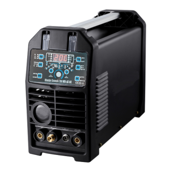
BLUEARC GENESIS 200 MIX AC/DC
WELDING MACHINE
NOTE: Please read this manual carefully before use.
Product Specifications and features are subject to change without
notice. While every attempt has been made to provide the most
accurate and current information possible at the time of publication, this
manual is intended to be a general guide.
1
Advertisement
Table of Contents

Related Manuals for Genesis 200 MIX AC/DC


Summary of Contents for Genesis 200 MIX AC/DC
- Page 1 V.02-220214 OWNER’S MANUAL BLUEARC GENESIS 200 MIX AC/DC WELDING MACHINE NOTE: Please read this manual carefully before use. Product Specifications and features are subject to change without notice. While every attempt has been made to provide the most accurate and current information possible at the time of publication, this...
-
Page 2: General Comments
WARNING! Please read these instructions before installing and commissioning the device. GENERAL COMMENTS Start-up and operation of the device should only be done after carefully reading this Operator's Manual. Damage to the device due to improper handling will result in the loss of warranty rights. - Page 3 Prevention of damage from electric arc on the eyes and human skin: • Wear protective clothing (gloves, apron, leather shoes). • Use shields or protective shields with a properly selected filter. • Use protective covers made of non-combustible materials and use a color of the lens that absorbs harmful radiation.
-
Page 4: General Description
soiled clothing. Do not remove the external covers when the device is connected to the power. Maintenance and repair work may only be carried out by authorized persons subject to the safety and operating conditions applicable to electrical equipment. 2. GENERAL DESCRIPTION This welding machine is used for manual welding by direct current and alternating current using Manual Metal Arc (MMA) and Gas Tungsten Arc Welding (GTAW), also known as Tungsten Inert Gas (TIG) welding. - Page 5 Spot / Dead (Interval) Time (S) 0.1~15.0 / 0.0~15.0 TIG Tungsten Dia (mm) 1.0, 1.6, 2.0, 2.4, 3.2 Frequency (Hz) 20~250 AC TIG Balance (%) Sync Set ± 10% Adjust Frequency (Hz) 0.5-20 MIX TIG Ratio 5-95 Efficiency (%) Power Factor 0.93 Protection Class(S) IP23...
- Page 6 4.1 Mode option (In the non-welding working state) LIFT TIG HF TIG 4.2 POLAR option (In the non-welding working state) DC output *DC MMA can weld a variety of electrodes such as basic electrode, acid electrode... *DC TIG can be used for welding most metals except aluminum, magnesium and its alloys.
- Page 7 4.3 PULSE option (In the non-welding working state) PULSE OFF PULSE ON MIX TIG:N/A 4.4 Welding torch on/off option (In the non-welding working state) 2T: Pressing the switch in the grip handle will activate the ionizer and ignite the arc. Welding is carried out with the switch pressed.
- Page 8 (3) Press the handle button, the welding current drop to the value of the crater current. (4) Release the handle button. The arc is extinguished, shielding gas flows out; The solenoid valve closes the gas flow, completing welding. Note: means press handle button; means release handle button SPOT: The welding time is limited by the settled time, and the other is same as 2T.
- Page 9 Panel adjustment (REM is off) In this mode, a remote amperage control cannot be used.The welding current is determined by the panel welding current setting value. Foot pedal adjustment (REM is on) Note: Foot pedal is default REM value. A foot pedal is needed in this mode. The maximum welding current output is determined by the panel welding current setting value.
- Page 10 VRD ON Generally used in damp or enclosed workplace. After turning on the VRD function, the Open circuit voltage is less than 15V, which minimizes the risk of electric shock caused by a higher open circuit. 4.7 WELDING CURRENT SYNC (In the non-welding working state, press“SYNC”) Manual The mode is suitable for professional welders, who know how to adjust the parameter to achieve the best...
- Page 11 4.8 Programs SAVE AND LOAD (In the non-welding working state, press “MEMORY” to save or load program) Program SAVE (1) When want to save the welding parameters, firstly press the "MEMORY" button and "SAVE" light. And the "CH" light is also on and the display shows the channel number.
- Page 12 5.SETTING Current Time Display Pulse Freq Duty cycle Welding current Base current upslope downslope Spot time MMA hot start MMA Arc force Dead (Interval)time Final current initial current Preflow time Postflow Option button-left Option button-Right AC Freq AC Balance knob MIX ratio MIX Freq HOT START &...
- Page 13 SPOT TIME (time of spot welding) – Spot welding time Adjustment range: 0.1~15.0 s - Duration of the impulse, allows you to adjust the DUTY CYCLE (pulse duty) depth of the penetration. The increase in width increases the depth of penetration, the reduction reduces the amount of heat entering the material, reducing the risk of burning thinner sheets or smaller elements.
- Page 14 MIX FREQ - It is used to adjust the exchange frequency of AC ARC and DC ARC, that is, the length of time for the arc combination of AC arc and DC arc to weld pool. For example: MIX FREQ is set to 5Hz, which means that the AC ARC and the DC ARC must be switched 5 times within one second, and the duration of each time is 1/5 second, that is, the mixing period is 200 milliseconds.
-
Page 15: Description Of Operation
For example: If the welder wants the weld corrugation to be denser, the MIX Freq can be adjusted higher. *Adjusting the MIX ratio can control the strength of the AC ARC and the weld penetration. For example: When the welder wants to increase the penetration depth to improve the weld quality when welding thick plates, he can set the MIX ratio to be smaller and use DC ARC to increase the penetration depth. - Page 16 6.1 MMA Method The ends of the welding cables should be connected to the sockets (1) and (4) on the front panel, so that the polarity of the electrode is on the electrode holder. The polarity of the welding cable connection depends on the type of electrode used and is given on the electrode packaging.
- Page 17 6.2 Tig Method The tig torch should be connected to gas connector (2) and remote socket (3) . The gas pipe from the reducer should be led and attached to the gas connector (8) located on the back of the housing. Connect the positive polarization socket (4) to the material to be welded with a wire with a earth clamp.
-
Page 18: Problem And Solution
7. PROBLEM AND SOLUTION In case of malfunction of the device, before sending the welder to the service, check the list of basic failures and try to resolve them yourself. Any repairs to the device may only be made after disconnecting the plug from the mains socket. - Page 19 List of codes: Over current protection The main power device of the welding machine is in the over-current working state, at this time the welding machine cuts off the output and the display shows “ALARM”. Over heating protection The welding machine is in an overload working state and the temperature of the main power device is too high.
-
Page 20: Maintenance Instructions
8. WELDING PARAMETERS RESTORE TO THE FACTORY SETTINGS If you need to reset all welding parameters to the factory default values, you can do the following operations: In the non-welding state, press both buttons together, and then hold for 5 seconds until all the indicators on the panel are off, the display show and panel has illuminated again. - Page 21 IGBT Equipment Warranty Welding Material Sales Effective Jan 1, 2019 Limited Warranty This warranty applies to the original purchaser and is subject to the terms and conditions listed below. This Limited Warranty is for new equipment sold after the above date, providing coverage for defects in material and workmanship at the time it is shipped from the factory.
Need help?
Do you have a question about the 200 MIX AC/DC and is the answer not in the manual?
Questions and answers