Table of Contents
Advertisement
Quick Links
Advertisement
Table of Contents

Summary of Contents for protech 500DSA
- Page 1 METAL CUTTING BAND SAW 500DSA/H INSTRUCTION MANUAL 500DSAH-1020403-R1...
-
Page 2: Table Of Contents
7 BI-Metal speeds and feeds .…………………….………………………………..9 8 Connecting saw to power source ………………………………………………..11 9 Starting and stopping machine (Model:500DSA)……………………………..12 9 Starting and stopping machine (Model:500DSAH) …………………………..13 10 Adjusting automatic shut-off limit switch……………..........16 11 Adjusting downward travel of saw arm …………………………………….. -
Page 3: Overall Aspect
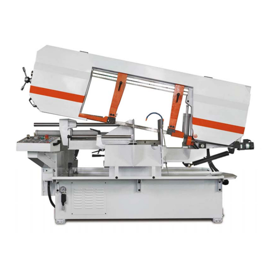
Overall Aspect Hand wheel Blade adjustable knob Control box Support rod Vise clamping pressure Auxiliary pulling spring Vise jaw bracket Saw blade brush CAUTION Install saw blade and blade guard before use. Set proper blade tension to prevent any danger caused by damaged saw blade or work piece. -
Page 4: Warning
1 WARNING: FAILURE TO FOLLOW THESE RULES MAY RESULT IN SERIOUS PERSONAL INJURY As with all machinery there are certain hazards involved with operation and use of the machine. Using the machine with respect and caution will considerably lessen the possibility of personal injury. - Page 5 (3). USE RIGHT TOOL. Don’t force tool or plugged into a three-hole electrical receptacle. attachment to do a job for which it was not If an adapter is used to accommodate designed. atwoprong receptacle, the adapter lug must be (4). SECURE WORK. Use clamps or a vise attached to a known ground.
- Page 6 be properly repaired or replaced. surfaces where fluid accumulates and does not (3). DISCONNECT TOOLS before evaporate quickly, such as between the servicing and when changing accessories such machine bed and vise. as blades, bits, cutters, etc. (4). MAKE SURE that blade tension and F.
-
Page 7: Specification
3 SPECIFICATION MOTOR 5HP,,( 3Φ) 32-96 MPM 60Hz 105-315FPM Saw Blade Speed 26-80 MPM 50Hz 85-262FPM Blade Size(mm) 41 x 1.3 x 5890L Dimension L x W x H (mm) 3000L x 1270W x 1730H N.W / G.W (kgs) 1590 / 1800 Packing Measurement 2930L x 1140W x 1981H... -
Page 8: Minimum Room Space For Machine Operation
Installation: As this machine weights 1320 kg. It is recommended that the machine shall be transported, with help of lifting jack. Transportation Recommendation: (1). Tighten all locks before operation. (2). ALWAYS Keep proper footing & balance while moving this machine. (3). -
Page 9: Make Proper Tooth Selection
6 MAKE PROPER TOOTH SELECTION For maximum cutting efficiency and lowest cost per cut, it is important to select the blade with the right number of teeth per inch (TPI) for the material being cut. The material size and shape dictate tooth selection. -
Page 10: Bi-Metal Speeds And Feeds
EXAMPLE: 4”(100mm) outside diameter, 3”(75mm) inside diameter tubing. 4”(100mm) OD =12.5 sq.ln. (79cm 3”(75 mm ) ID = 7.0 sq.ln. (44cm Area = 5.5 sq.ln. (35cm 5.5 sq.ln. (35cm ) / 4” (100mm) distance =1.38(35mm) average width 1.38” (35mm), use a 4/6 Vari-Tooth NOTE: The band speed and cutting rate recommendations presented on this chart are approximations and are to be used as a starting point for most applications. - Page 11 1030 1008,1015,1020,1025 1035 1018,1021,1022 1026,1513 A36(SHAPES),1040 1042,1541 1044,1045 1060 1095 Ni-Cr-Mo 8615,8620,8622 Alloy Steel 4340,E4340,8630 8640 E9310 Tool Steel A-10 H-11,H-12,H-13 Stainless Steel 410,502 440C 304,324 304L 316,316L...
-
Page 12: Connecting Saw To Power Source
TELLTALE CHIPS Chips are the best indicator of correct feed force. Monitor chip information and adjust feed accordingly. Thin or powdered chips – increase feed rate or reduce band speed. Burned heavy chips – reduce feed rate and/or band speed. Curly silvery and warm chips –... -
Page 13: Starting And Stopping Machine (Model:500Dsa)
9 STARTING AND STOPPING MACHINE (Model:500DSA) 9-1 Control Panel Introduction: (Fig. 1) A. Main Switch with Key B. Power Indicator Light C. Breakdown Indicator D. Saw Bow Down Feed Rate Control E. Counter for Cutting Pieces F. Auto Cycle Cutting Start Switch G. -
Page 14: Starting And Stopping Machine (Model:500Dsah)
9 STARTING AND STOPPING MACHINE ( FOR SAW BOW LEFT-RIGHT ELECTRICAL (Model:500DSAH) ANGLE SWIVEL ) 9-1 Control Panel Introduction: (Fig. 1) (Fig. 1-1) A. Main Switch with Key B. Power Indicator Light C. Breakdown Indicator D. Saw Bow Down Feed Rate Control E. - Page 15 9-2 Auto Counter for Cutting Pieces (E) Provide auto accumulation. Press to reset. 9-3 Saw Bow Up-Down and Left-Right Control Section (H) Attention: 1. the left light of readout is flashing, it means the number is inputting into the program. When the light extinguished, it means the number is ready to input into the program.
- Page 16 When target angle is 45 degree, the saw bow will only move between the 45 degrees and minus 45 degrees, won’t over this degree. (This Max angle setting of RF-500DSA is 60 degree and minus 60 degree.
-
Page 17: Adjusting Automatic Shut-Off Limit Switch
Saw blade run Saw bow down (please adjust the down feed rate by manual.), cutting begin. Cutting complete Saw blade stop Saw bow up to the limit Vise open work piece released. 10 ADJUSTING AUTOMATIC SHUT-OFF LIMIT SWITCH An automatic shut-off limit switch is provided to stop the motor when the cut is completed. -
Page 18: Changing Saw Blade Speeds
12 CHANGING SAW BLADE SPEEDS This machine is available for variable speed selection. Speed range is 32~96MPM (Fig,4). When changing the speed, turn the speed dial (A) watch the LED (B), select the desired speed ** Please refer to TPI and saw blade speed selection chart in this manual, for the reference of cutting relative work piece and material with proper feeding. -
Page 19: Adjusting Feed Rate
15 ADJUSTING FEED RATE When the feed rate control knob is turned clockwise as far as it will go the saw frame will not move down, but it can be raised to the up position. By turning the feed rate control knob counter clockwise, the flow of oil from the cylinder is regulated and determines the speed at which the saw frame will lower and the blade will feed through the work. -
Page 20: Operating Cutting Angle And Adjusting Vise
17 OPERATING CUTTING ANGLE AND ADJUSTING VISE The swivel angle is positioned every 15 degrees. The cutting slot Fig,10(A) on working table is in 45 and 60 degrees angle. But you can cut at any angle with reference of the angle scaleFig,11(A). If you are cutting in the multiples of 15 degrees, please operate as follows: Move the swivel lock handle Fig,11(B) to the right... -
Page 21: Coolant
18 COOLANT The use of proper cutting fluid is essential to obtain max-imum efficiency from a band saw blade. The main cause of tooth failure is excessive heat build-up. This is the reason that cutting fluid is necessary for long blade life and high cutting rates. -
Page 22: Removing And Installing The Blade
3. The blade guide bearings are to introduce saw blade into vertical position. The bearing shaft on user side is an adjustable eccentric, when the other side is a non-adjustable concentric. When adjusting, loosen the bolt (G), turn the sleeve (H) clockwise by wrench, bring the bearing surface close to saw blade surface. -
Page 23: Gear Box
22 GEAR BOX The gear box should be drained and refilled after the first 50 hours of use and thereafter every 5 months, with mobile synthetic gear oil, SHC-636, ISO viscosity grade 680. this oil meets or exceeds American gear manufacturers association (A.G.M.A.) #8 compounded cylinder oil specifications. -
Page 24: Saw Blade Brush Setting
23 SAW BLADE BRUSH SETTING (Fig.22) The brush is to remove the chip on the saw blade tooth. Place the brush to touch the blade 3~5 mm in depth. Normally, a large number of chips will be sitting under the brush. Cleaning timely is necessary, to ensure the function of the brush cleaning, and to prevent the unnecessary damage by steel chip going into the saw blade wheel. -
Page 25: Vise Clamping Pressure Setting
26 VISE CLAMPING PRESSURE SETTING This machine provides adjustable vise clamping pressure, convenience for clamping workpieces of different materials, particularly the easily deformed tubes. To adjust the pressure, loosen the upper bolt (A)Fig.26, turn the lower knob. Watch the changing of the pressure volume on the meter. Select the smallest material deformation with the proper clamping pressure. -
Page 26: Trouble Shooting
28 TROUBLE SHOOTING Symptom Possible Cause(s) Corrective Action Machine can not be started 1.Power is not plugged; the power 1. Check motor light on control panel is not on. specification; connect 2.Motor can not be started; power power with correct power was cut by limit switch. - Page 27 and adjust blade tension 7. Insufficient blade 7. Tighten blade tension adjustable knob 8. Blade slide 8. Tighten blade tension Unusual Wear on 1.Blade guides worn. 1.Replace. Side/Back of Blade 2.Blade guide bearings not adjust 2.Adjust as per operators properly manual 3.Blade guide bearing bracket is 3.Tighten.
- Page 28 Bad Cuts (Rough) 1. Too much speed or feed 1. Decrease speed or feed. 2. Blade is too coarse 2. Replace with finer blade. 3. Blade tension loose 3. Adjust blade tension. Blade is twisting 1. Cut is binding blade. 1.
-
Page 29: Circuit Diagram
29 Circuit Diagram... -
Page 38: Parts Lists
MOLD:500DSAH PART LIST CODE_NO PART_NO SPECIFICATION DESCRIPTION MATERIAL NOTE 151010 Body Frame SS41 1.00 S45C 1.00 151001-4 Shaft s30c 1.00 151001-9 Screw Shaft 151016 Reducer SS41 1.00 M6(染黑) 4.00 HW004B Washer M6X12L 4.00 HS334 Hex. Socket Head Screw 1.00 151063 Screw rod washer 鐵氟龍... - Page 39 1.00 151091 Scale HT001 M5X10L 6.00 Round Head Screw 151078 1.00 Blade Tension Sliding Plat SS41 151080 Shaft S45C 1.00 151077 2.00 Screw rod washer SS41 151076 Press Board 2.00 SS41 HW106 Spring Washer 6.00 M10X65L 6.00 HS267 Hex. Socket Head Screw 1.00 151079 Abjustable...
- Page 40 68-3 151193 Bracket 1.00 SS41 68-4 151194 Bracket 1.00 橡膠 68-5 151195 Press Board 1.00 SS41 151042 Gear Box FC25 1.00 70-1 1.00 151042-1 Gear Box FC25 HW107 Spring Washer 6.00 HS280 M12X30L Hex. Socket Head Screw 6.00 HS439 M10X15L Hex.
- Page 41 123-1 3.00 195058 Packing 橡膠 1.00 151167 Brush Shaft A S30C Brush Support A 1.00 151165 SS41 125-1 DU121420 DU-12X14X20L Bearing 2.00 191334A Brush 1.00 M6(染黑) 2.00 HW004B Washer HW104 Spring Washer 1.00 2.00 HB802 Brush Support B 1.00 151166 SS41 M8(染黑) 2.00...
- Page 42 151241 1.00 Bottom Cover SS41 HW004B 2.00 Washer M6X12L 2.00 HS334 Hex. Socket Head Screw 151237 Connect Shaft S30C 1.00 HK108 8X7X35L 1.00 1.00 151230 Motor Plate SS41 HW023B Washer 2.00 HS259 M10X25L 2.00 Hex. Socket Head Screw 198201MA E-1/40 1.00 Gear Box HW105...
- Page 43 M8(染黑) 1.00 HW005B Washer HW105 Spring Washer 1.00 M8X20L 1.00 HS242 Hex. Socket Head Screw 151135 Chunk S30C 1.00 HP030 6X15L 2.00 Spring Pin 151136 1.00 Bracket S30C HS462 M6X8L Hex. Socker Headless Screw 1.00 M8X30L 2.00 HS244 Hex. Socket Head Screw 151137 1.00 Release Block...
- Page 44 151232 1.00 Worm S30C HP035 8X15L 2.00 Spring Pin HW106 Spring Washer 5.00 HS261 M10X35L Hex. Socket Head Screw 5.00 151244 1.00 314-1 HW004B M6(染黑) 2.00 Washer 314-2 HS229 M6X15L Hex. Socket Head Screw 2.00 151046 1.00 Spring Bracket A FC25 HW105 Spring Washer...
- Page 45 355-4 M22XP1.5(細牙)(染黑 Hex. Nut 1.00 HN019B 355-5 Stop Block Support 1.00 103039A FC20 355-6 Knob 1.00 193053 355-7 151192 M8XP1.25*20L Knob 1.00 355-8 1.00 151191 Distance Set Rod S20C 355-9 M10xP1.5(染黑) 1.00 HN006B Hex. Nut 355-10 HS061B M10X35L(染黑) Hex. Head Screw 1.00 151001 1.00...
- Page 46 Hex. Socket Head Screw 一般AA用 1.00 151105 Hydraulic Unit S30C 480-40S 151106 Hydraulic unit Adjustment Valve 480-1 1.00 151105-1 480-10S 500DSA整台份 Cylinder Fittings Assembly 1.00 151001-1 1.00 Bracket A SS41 M6(染黑) 4.00 HW004B Washer M6X12L 4.00 HS334 Hex. Socket Head Screw HS122B M16x75L(染黑)
- Page 47 HN008B M16(染黑) 4.00 Hex. Nut 151141 Washer 4.00 FC25 1.00 151124 Support FC20 151126 Screw rod washer S45C 2.00 M12(染黑) 2.00 HW049B Washer 2.00 151151 Knob 鋁鋅 151125 Support FC20 1.00 151121 Blade Adjustable (Rear) 1.00 FC20 HW023B M10(染黑) 4.00 Washer M10X40L 4.00...
- Page 48 M8X10L Hex. Socker Headless Screw 1.00 HS430 1.00 151149 Leadscrew S30C 1.00 151148 Bushing S45C 151147 Handle Rod S45C 1.00 HP019 5X25L 1.00 Spring Pin 1.00 151146 Hand Rod S30C HT016 M6X12L Round Head Screw 2.00 577S YB51P010 Toolbox Set 1.00 578S YB51P020...
- Page 49 MANUFACTURER: ADDRESS: SERIAL No.: PLEASE WRITE DOWN THE SERIAL NO. ON THIS BLOCK FROM THE NAME PLATE AFTER YOU RECEIVE THIS MACHINE.
Need help?
Do you have a question about the 500DSA and is the answer not in the manual?
Questions and answers