Advertisement
Quick Links
®
PRO-III
OPERATIONS MANUAL
TAPCO PRODUCTS CO.
A DIVISION TAPCO INTERNATIONAL
Port-O-Bender
®
Featuring
• Accessories
• Setup and operating instructions
• How to form the most popular shapes
• Hints and shortcuts to greater profits
with your Tapco Pro-III
• Tune-up instructions
• Complete parts list
Pro-III Port-O-Benders are made under one or more of the following U.S. Patents:
3,161,223
4,321,817
4,372,142
4,766,757
3,482,427
4,494,397
The Industry Leader Since 1960
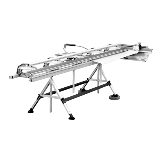
Tapco PRO-III Port-O-Bender
shown with optional Tapco
Side-Winder, Pro-Filer,
Pro Cut-Off and Pro-Stand .
®
Port-O-Bender
4,651,553
4,489,583
4,493,200
4,445,356
3,817,075
4,557,132
4,240,279
4,671,094
3,559,444
5,343,728
5,353,620
5,505,069
Other U.S. & Foreign Pats. Pend.
$5.00
Price:
© Copyright 2001
®
®
®
Advertisement

Subscribe to Our Youtube Channel
Related Manuals for Tapco Port-O-Bender PRO-III

Summary of Contents for Tapco Port-O-Bender PRO-III
- Page 1 Port-O-Bender ® ® OPERATIONS MANUAL ® The Industry Leader Since 1960 TAPCO PRODUCTS CO. A DIVISION TAPCO INTERNATIONAL Tapco PRO-III Port-O-Bender shown with optional Tapco Side-Winder, Pro-Filer, Pro Cut-Off and Pro-Stand . Featuring • Accessories • Setup and operating instructions •...
- Page 2 ® The TAPCO PRO-III Port-O-Bender ® ® The world’s best selling portable bender Pro-III Features Computer designed die castings make this the strongest portable bender ever! Unique “Positive Toggle Locking System” provides positive clamping without guesswork. Widest mouth opening in the industry 2 ", with built-in...
-
Page 3: Parts List
PRO-III ® PORT-O-BENDER ® PARTS LIST NOTE: All multiples of the same part may not be called out. Part Number Part Name Part Number Part Name 10094 1/4-20 Hex Flange Nut 10547 Base Hinge Cap - Right 10349 Coupling Nut 10548 Base Hinge Cap - Left (not shown) 10351... - Page 4 SETTING UP YOUR PORT-O-BENDER ® Hemming Handle Installation Hemming Handle Faspin Handle Plug Locking Handle Hex Bolt " Now tighten the 3/8 Hex Bolts with a The PRO-III Hemming Handle As- Insert Hex Bolt through Locking Handle " 9/16 wrench. Handle can be detached sembly includes: (1) Hemming Han- of your Port -O-Bender and into base from now on by simply removing the...
- Page 5 ADJUSTING YOUR PRO-III PORT-O-BENDER ® Pivot Link Adjustment Instructions IMPORTANT: Your Port-O-Bender incorporates an advanced new Micro-Adjust system that enables you to adjust the ® gripping tension on material faster and easier than ever. The Pivot Links have been pre-set at the factory for average holding capacity and ease of operation.
- Page 6 Care and Maintenance of your Port-O-Bender ® Capacities ® Your Tapco Port-O-Bender is virtually maintenance free and will provide you with years of reliable and trouble-free performance, however, there are a few PRO-III Bending Capacities ® basic necessities required to keep your Port-O-Bender like new.
- Page 7 This TIGHT!! saves time and ensures accuracy. The Tapco Pro-Filer was designed to make this time consuming part of your job easier Remember, when designing shapes you are hanging a cover and more accurate.
- Page 8 EXAMPLES OF COMMON TRIM SHAPES “Finish Side Up” indicates that the exposed or finish side of the trim material is to be placed in the Bender facing up. 1. All Purpose Sill Trim Finish Side See notes on Bending the Roof or Down Drip Edge “General Instructions for All Examples”...
- Page 9 EXAMPLES OF COMMON TRIM SHAPES “Finish Side Up” indicates that the exposed or finish side of the trim material is to be placed in the Bender facing up. Finish 6. One Piece Outside Corner Side Finish Down Side Down Finish Side Finish Side...
- Page 10 TAPCO ACCESSORIES— A Necessity for Today’s Professional Sider ® TAPCO PRO-FILER (See page 13) “Inside out” — Eliminates layout time and need position for coil to snip mark your coil for measuring. — Simply feed coil in, the Pro-Filer squares and measures in one opera- tion, you simply bend.
- Page 11 THE “PRO-III COMPLETE” SAVES TIME, INCREASES PROFITS The “Pro-III Complete” system includes: Pro-III Port-O-Bender, Pro Cut-Off, Side-Winder, Tapco Pro-Filer and Pro-Stand. On an average day, they can save you hours on the job site! Side-Winder Pro-Stand time savings: time savings: 15 min.
- Page 12 (Coil loaded especially on windy days. finished side up) • Holds up to 24"x100' coil (when used with Pro- When using Tapco SIDE-WINDER, Stand). Weighs only 25 lbs. PRO CUT-OFF must be used to cut off material. Both optional • New improved versatility! Coil can be drawn out...
- Page 13 OTHER ACCESSORIES & MAJOR ITEMS TAPCO PRO-FILER ® Automatic Squaring and Measuring Gauge PRO-FILER Features Attaches to the back of your PRO-III • Automatically squares material fed into your Port-O-Bender and keeps all your bends parallel. • Eliminates measuring, marking or snipping on your coil •...
- Page 14 • Rip cuts up to 48" wide, any length • Self-storing reversible 5 foot long Work Support Extension with • Single handle controls all settings built-in fence—A Tapco exclusive! • Accepts most 7 " or 8 " full •...
- Page 15 OPTIONAL PRO-STAND & LIGHT DUTY LEGS SET UP Pro-Stand Setup Instructions DETAIL Cross Brace Detail DETAIL PRO 2000 PRO III Only FRONT OF BENDER Steps (indicated above) 1. Remove all parts from box. Attach 2 x 4 Bracket to Vertical Support using 1/4-20 x 1 1/2"...
-
Page 16: For Your Records
• Soffit and Frieze • Utility or Finish Trim • Custom Shapes DISTRIBUTED BY ® TAPCO PRODUCTS COMPANY A DIVISION OF TAPCO INTERNATIONAL Plymouth, MI 48170-6010 U.S.A. Telephone: (734) 451-8272 • Fax: (734) 451-0702 10816 B Web site: www.tapcoint.com T1016-AG 4/01...
Need help?
Do you have a question about the Port-O-Bender PRO-III and is the answer not in the manual?
Questions and answers