
Summary of Contents for MECOS IMC15
- Page 1 Magnetic Bearing and Motor Controller IMC15 BG10837-XXN Operating Instructions Rev_E 02/2021...
- Page 2 (c) 2021 MECOS AG Hardstrasse 319 CH-8005 Zürich SWITZERLAND Tel. +41 52 355 52 11 Fax +41 52 355 52 24 mecos@mecos.com www.mecos.com Specifications are subject to change without notification.
-
Page 3: Table Of Contents
Table of Contents ABLE OF ONTENTS ..........1 YSTEM VERVIEW ..........2 EMARKS ON AFETY 2.1 UL Markings ............... 2 ............ 4 NTENDED ............. 5 NSTALLATION 4.1 Overview ..............5 4.2 Mounting ..............6 4.3 Electrical Connectors ........... 7 4.3.1 Introduction ..............7 4.3.2 Magnetic Bearing Connectors ........7 4.3.3 Motor Terminal Block ...........8 4.3.4 Line Terminal Block ............9... - Page 4 5.6.1 Introduction ............. 30 5.6.2 Flash Card and Handling ..........30 5.6.3 Complete Update ............32 5.6.4 Inifile Update ............34 5.6.5 Display Update ............36 ..........38 ROUBLESHOOTING 6.1 Fault Categories ............38 6.2 Error Messages by Categories ........39 6.3 Troubleshooting Procedures ........
-
Page 5: System Overview
DC bus (generator operation). Acting as interfaces to the IMC15 are a display with a keypad, a CAN bus interface and a digital interface (Dig I/O) that can be configured to meet specific requirements. -
Page 6: Remarks On Safety
IMC15 EMARKS ON AFETY During operation, the IMC15 and the electric drive system as a whole may, according to its degree of protection, have moving or rotating parts as well as hot surfaces. Electric drive systems with frequency converters are therefore potentially hazardous. - Page 7 2 Remarks on Safety 56.2 Overload, Over-Current, and Over-Speed Protec- tion The motor must have an integral thermal protection PTC according to DIN 44082. The PTC must be connected to the terminal block J2. Max. Motor rating: 29.5Arms AC, 15kW. Le moteur doit avoir une protection intégrée contre surtempé- rature PTC selon DIN 44802.
-
Page 8: Intended Use
IMC15 NTENDED The IMC15 is intended for use in electrical plants or machines. If used in machines, the commissioning of the IMC15 (start of the intended use) has to be delayed until it has been verified that the machine complies with the regulations of EU directive 98/37/EG (directive for machines). -
Page 9: Installation
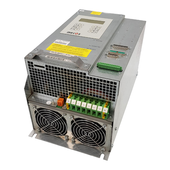
4 Installation NSTALLATION 4.1 Overview 1. Display (LCD) 2. Keypad 3. Mounting rail for magnetic bearing cabling 4. Slot for flash memory card 5. Dowel pin for electrical shield connection 6. Terminal block for stator winding temperature monitoring by PTC (cage clamp: AWG 26-14, 0.14-1.5 mm 7. -
Page 10: Mounting
Due to the heating of the device under operation, the following spacings have to be respected for the installation: The IMC15 is listed as an „open type device“ and must be installed into a machine or a plant. Installations that allow... -
Page 11: Electrical Connectors
4 Installation 4.3 Electrical Connectors 4.3.1 Introduction All installation work has to be carried out by qualified person- nel and according to appropriate regulations. The electrical connections have to be carried out using the connection diagram in the appendix. Since this is an applica- tion-specific document, it has to be ensured, that the correct document (correct version of this manual) ist being used. -
Page 12: Motor Terminal Block
Never operate any motor without prior con- sent of MECOS AG. If the motor is equipped with a PTC for stator winding tempe- rature limit monitoring, it can be connected to the terminal... -
Page 13: Line Terminal Block
Conventions of the respective switching cabinet wiring have to be respected. Special attention has to be paid to the following points: • Always use the line filter specified by MECOS AG (mfr Schaffner EMC, Type FN3258-30-33 or FN3258-30-47, or mfr. FUSS, type 3F460-030.270). -
Page 14: Connectors Of The Customer Specific Interfaces
IMC15 4.3.5 Connectors of the Customer Specific Interfaces Dependig on the model of IMC15 one or more of the following connectors may be provided: Designation Function Connector X5 Multipur- Measurement pose signals D-Sub 9 pin, male X6 CAN Field bus... -
Page 15: Emc Issues
4 Installation 4.3.6 EMC Issues The IMC15 has been designed to fulfill the low voltage direc- tive as well as the EMC directives provided the installation has been carried out correctly. EMC- certification has been obtai- ned in an accredited laboratory. The results may not be uncon- ditionally applied to any type of installation containing an IMC15. - Page 16 IMC15...
-
Page 17: Operation
5 Operation PERATION 5.1 Display and Keypad The alphanumeric display has 4 rows of 20 characters each. The text-based menus are supported by 5 addtional symbols. The keypad consists of 6 push buttons whose respective func- tions are explained by a symbol or a piece of text. 3 push but- tons are equipped with light emitting diodes (LED) for an additional indication of the device state. - Page 18 IMC15 Name Function Menu title Title of menu page Context depen- Navigating through and choosing from dent symbol menus Menu number Number of the displayed menu Navigation aid Inidicates, if there are further menus available by pushing „up“ or „down“...
- Page 19 5 Operation Symbols: Symbol Function Indicates Navigation aid See further options by pressing „up“ Navigation aid See further options by pressing „up“ or „down“ Navigation aid See further options by pressing „down“ Context depen- Choose from a menu dent symbol Context depen- View contents of fault history or cur- dent symbol...
-
Page 20: Navigation Using The Keypad
IMC15 5.2 Navigation using the Keypad The navigation is based on screens, which are organised in 4 modes to form a menu structure. By using the keypad, screens can be displayed and their contents be either chosen (activated) and/or displayed. - Page 21 5 Operation...
-
Page 22: Menus
The menu tree shown below provides an overview over the menus that can be accessed using the display and the keypad of the IMC15. The 4 modes „Main Menu“, „AMB“, „Drive“ and „Current Faults“ can be accessed using the „Mode“ Button. The... -
Page 23: Mode 1: Main Menu
5 Operation... - Page 24 IMC15...
-
Page 25: Mode 2: Amb
5 Operation 5.3.3 Mode 2: AMB In the AMB mode all important AMB values can be viewed. 2 AMB Functions Menu Item Description Subpage #1: Displays the AMB displacements in per- AMB Displacements cent of the maximum admissible dis- placements Subpage #2: Displays the AMB forces in percent of AMB Forces... -
Page 26: Mode 4: Current Faults (Fault And Warning Monitor)
The device supervision is activated automatically when starting up the IMC15 and copies all faults and selfcheck faults occurred to the fault history (warnings are not written to the fault history). -
Page 27: Fault And Warning Monitor
5 Operation 5.4 Fault and Warning Monitor 5.4.1 Introduction As soon as powered up, the IMC15‘s device supervision is active. There are two distinct phases: Phase 1: Selfcheck during powerup During powerup, the firmware is being booted and the device... - Page 28 IMC15 After successfully passing the selfcheck, Menu Page 1 („Main Menu“) is displayed, the rotor is lifted up and the green led is lit. If one or more of these tests fail, Menu Page 1 is displayed and the red led is lit. The device is locked with either a „Perm“...
-
Page 29: Using The Fault And Warning Monitor
5 Operation 5.4.2 Using the Fault and Warning Monitor With the fault and warning monitor the current faults and war- nings can be viewed and faults can be reset. a) Viewing of current faults and warnings Explanatory Note: The selfcheck monitor in the main menu is used in the same way as the fault and warning monitor and allows to display the selfcheck warnings as well as selfcheck faults that have led to the locking of the device by a „Perm“... - Page 30 IMC15 b) Resetting of current faults...
-
Page 31: Fault History
5 Operation 5.5 Fault History 5.5.1 Introduction The fault history holds all faults and selfcheck faults that have occurred. It consists of a list of 160 entries that are periodi- cally overwritten (wrap around after 160 faults). It can be accessed sequentially with the last („youngest“) entry being at the top. -
Page 32: Using The Fault History
IMC15 5.5.2 Using the Fault History The fault history is accessed through the main menu. In order to view the fault history, the data has to be buffered first (menu page 121). After this, all fault entries can be viewed (menu page 122) and, if more information is required, its cau- ses (details) can be displayed (menu page 123). - Page 33 5 Operation b) Viewing the causes (details) of a fault entry...
-
Page 34: Updating The Firmware
5.6.1 Introduction In order to prevent a factory recall in case of a firmware update, the IMC15 can be updated using portable flash cards. The firmware consists of three parts. The program code, the parameter files (inifiles) and the display file. As will be descri- bed in the following sections, it is possible to either update the whole firmware or only parts of it. - Page 35 After successfully carrying out the update (see following sec- tions) the card has to be removed from the slot and can be used for updating any number of further IMC15 devices. Please keep in mind the following points: • Updates of any kind may only be carried out by qualified personnel using flash cards that have been explicitly made for this application by MECOS AG.
-
Page 36: Complete Update
If the version number of the program on the IMC15 (Menu page 141 „Version Info“) and on the flash card correspond, no update will be carried out, meaning that neither program nor inifiles nor display files will be updated. - Page 37 5 Operation...
-
Page 38: Inifile Update
Inifiles work with exactly one program version. The IMC15 will not carry out an inifile update if it is not intended to be used with the program version on the device to be updated. Since... - Page 39 5 Operation...
-
Page 40: Display Update
IMC15 5.6.5 Display Update If the display‘s contents are to be modified, a display update has to be carried out. The proceeding of the display update is identical to the the ini- file update. Should there be necessity to update both inifile and display file, it can be done simultaneously provided both updates are stored on the same flash card. - Page 41 5 Operation...
-
Page 42: Troubleshooting
In order to facilitate diagnosis, all warning and fault messages of the device supervision are assigned to one of the following 9 categories. Fault category Description IMC15 is defective Replace IMC15 Sensor fault Defective sensor cabling possible. Check sensor cabling and installation first. -
Page 43: Error Messages By Categories
6 Troubleshooting... -
Page 44: Troubleshooting Procedures
IMC15... - Page 45 6 Troubleshooting...
- Page 46 IMC15...
- Page 47 6 Troubleshooting...
- Page 48 IMC15...
- Page 49 6 Troubleshooting...
- Page 50 IMC15...
- Page 51 6 Troubleshooting...
- Page 52 IMC15...
- Page 53 6 Troubleshooting...
- Page 54 IMC15...
- Page 55 6 Troubleshooting...
- Page 56 IMC15...
-
Page 57: Maintenance
7 Maintenance AINTENANCE If used as intended, the IMC15 is not subjected to any sub- stantial wear, thus, maintenance is not necessary. -
Page 58: Technical Data
IMC15 ECHNICAL DATA General Data Dimensions and Heigth [mm] weight Width [mm] Depth [mm] Weight [kg] Electrical data Input power [kVA] Input voltage 400 VAC +/- 10% (EUR) [VAC] 460 VAC +/- 10% (USA) Total efficiency @ 25 °C [%]... - Page 59 1100Hz at 14kW Temperature sensor incorporated into the stator windings of the motor. Processing by IMC15: Short detection during self- check (fault condition: R < 80 Ohm), detection of cable interruption or overtemperature during operation (fault condi- tion: R >...
- Page 60 IMC15 Power amplifier Bus voltage [VDC] 100 nominal, adjustable up to 140 Output current (maximum) [A] Channels Sensors 0.1 ... 1000 Range [ Resolution 0.02% of range Linearity deviation < 10 Processor Type TMS 320 F 2407 APGEA Flash 32 k...
-
Page 61: Declaration Of Conformity
9 Declaration of Conformity ECLARATION OF ONFORMITY... -
Page 62: Warranty
IMC15 10 W ARRANTY Unless otherwise noted, please refer to MECOS' Standard Terms & Conditions (AGB). This warranty void by any attempt to open the device and/or carry out repairs or modifications without prior and written consent of MECOS AG. -
Page 63: Appendix
11 Appendix 11 A PPENDIX • Dimensions in millimeters / master gauge for mounting holes... - Page 64 IMC15 • Digitale Interface (Digital I/O) Electrical Specifications Uout No Load 25 V @200mA 23.2 V @ Ta = 55 °C Iout Maximum 0.2 A @ Ta = 55 °C Digital Out Umax 80 V Open collector output 10 mA...
-
Page 65: Glossary
Allows flexible, compact and efficient digital circuit designs. Dig I/O Digital I/O Custom specific interface of the IMC15 featuring digital inputs and outputs as well as an isolated 24 VDC power supply. Displayfile File containing the menu and screen pages defin- ing the user interface of the display. - Page 66 IMC15 Term Definition Positive Temperature Coefficient Commonly used abbreviation for temperature dependent resistors with positive temperature coefficients, meaning increasing resistance with raising temperatures. Real Time Clock Lithium battery buffered clock unit. In addition to time and date it stores, operating hours and shut- down as well as TDBWear counters.
Need help?
Do you have a question about the IMC15 and is the answer not in the manual?
Questions and answers