Table of Contents
Advertisement
Quick Links
Advertisement
Table of Contents

Subscribe to Our Youtube Channel
Related Manuals for Scame BE-T Series


Summary of Contents for Scame BE-T Series
- Page 1 USER MANUAL BE-T SERIES...
-
Page 2: Table Of Contents
BE-T USER MANUAL CONTENTS GENERAL INFORMATION AND WARRANTY ASSEMBLY INSTRUCTIONS CABLING INSTRUCTIONS ADDITIONAL INFORMATION PRODUCT DESCRIPTION FREE MODE PERSONAL MODE NET OPERATION ERRORS PROGRAMMER POWER MANAGEMENT (OPTIONAL) SCAME APP CHAIN2 ACTIVATION MAINTENANCE AND SUPPORT ACTIVATION CODE e-mobility@scame.com... -
Page 3: General Information And Warranty
Given that improvement is continuous, we reserve the right to make changes to the product and this manual at any time. • The total or partial reproduction of this manual without the prior consent of Scame Parre S.p.A. is prohibited. HAZARD: Risk of electrical shock, explosion or electric arcs •... -
Page 4: Assembly Instructions
BE-T USER MANUAL TECHNICAL FEATURES • Rated current: 32A • Rated voltage: 230Vac-400Vac • Rated frequency: 50-60 Hz • Insulation voltage: 250V-500V • Protection rating: IP54 • Installation temperature: -30°C +50°C • Material: Thermoplastic/Aluminium • Self-extinguishing behaviour: (GWT): 650°C • Impact resistance (IK rating): IK09 •... - Page 5 ASSEMBLY INSTRUCTIONS ART. 205.Txxx MONTAGGIO / MOUNTING / MONTAGE / MONTAJE 52.5 MAX PG 21 CABLAGGIO / WIRING / CÂBLAGE / CABLEADO SERIAL LINE TCP/IP LINE A+ A- 0,5 mm² RJ45 ES. BELDEN 9841 CAT5 POWER SUPPLY N PE L1 L2 L3 N PE 2,5÷16 mm²...
- Page 6 BE-T USER MANUAL...
-
Page 8: Cabling Instructions
BE-T USER MANUAL CABLING INSTRUCTIONS SYSTEM REQUIREMENTS • Check the following electrical values: ◊ Grounding system: TT, TN(S), TN(C), ◊ Phase to phase voltage (L-L): between 380 and 400Vac inclusive ◊ Phase to neutral voltage (L-N): between 220 and 230Vac inclusive ◊ Neutral to ground voltage (N-PE): less than 5Vac ◊ Frequency (f ): 50 or 60Hz ◊ Ground resistance (Rt): less than 50Ω... -
Page 9: Additional Information
ADDITIONAL INFORMATION SCU: controller board SW1: reboot button. • Press briefly to restart the station. • Long press (>20S) will reset the board to the default configuration with controls disabled. Caution: the default configuration is to be used only in the event of an emergency and may not work correctly on some versions, and the original configuration must be restored as soon as possible. -
Page 10: Product Description
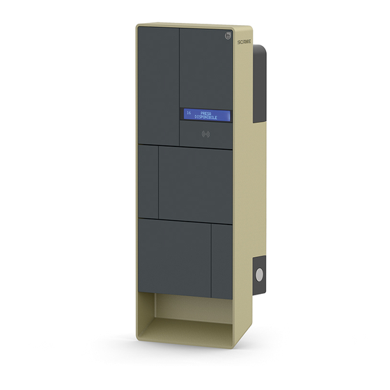
BE-T USER MANUAL PRODUCT DESCRIPTION Depending on the version, the stations can be equipped with: 1. Display (multi-language). Only for versions w/o APP 2. RFID reader (Mifare Classic or Mifare Plus). 3. LED - RGB strip 4. Button: Only for versions w/o APP •... - Page 11 *for versions with no APP...
- Page 12 BE-T USER MANUAL DISPLAY VISUALISATION Current set value State WAIT FOR EV Full scale value IN CHARGE SUSPENSION Way of charging NET mode: Address T: Typical PERSONAL mode: PM S: Simpli ed IN CHARGE 16/32T Pist 0.0KW 01:24s Cyclical display Charge duration Pist: Instant power Pest: External power...
-
Page 13: Free Mode
FREE MODE STATION ACCESSIBLE TO ALL PERSONS BE-T Stations G: Green B: Blue NB: Disconnection of the cord-set from the station is mandatory following charging. To begin a new charging session, re-connect the cord-set to the station. CHANGE MODE • Terminate charging in progress •... - Page 14 BE-T USER MANUAL Status RGB LED Description Station not powered × × SCAME PARRE Supply power to station ((( 2 ))) (firmware release) Station powered SOCKET AVAILABLE Insert plug in socket PLUG INSERTED Connect vehicle ((( 2 ))) WAITING FOR EV...
-
Page 15: Personal Mode
PERSONAL MODE STATION WITH RESTRICTED ACCESS VIA USER CARD BE-T Stations USER CARD USER CARD G:Green B: Blue NB: Disconnection of the cord-set from the station is mandatory following charging. To begin a new charging session, re-connect the cord-set to the station. CHANGE MODE •... - Page 16 BE-T USER MANUAL Status RGB LED Description Station not powered × × SCAME PARRE Supply power to station ((( 2 ))) (firmware release) Station powered CARD PRESENT Present card ((( 2 ))) INSERT PLUG Insert plug in socket ((( 2 )))
- Page 17 USER MANAGEMENT PRESENT NEW USER CARDS • With the station in PERSONAL mode (display: PM PRESENT CARD) • Show the master card on the RFID reader to enter programming mode (display: DATABASE MANAGEMENT – PRESENT CARD) • Show the user card on the RFID reader to be inserted into the memory (display: ID REGISTER –...
-
Page 18: Net Operation
BE-T USER MANUAL NET OPERATION (OCPP) REMOTELY MANAGED STATION • NET: list of authorised users included in the local server memory • OCPP: list of authorised users included in the central station memory CONNECTION INSTRUCTIONS SCU electronics-only connection system NET TCP/IP... - Page 19 NETWORK CABLE TYPE F/UTP CAT6 IN SEPARATE TUBE Mutual Capacitance < 10 pF/m Capacitance Unbalance < 60 pF/m Blue/white pair: Blue : A+ White : A- Brown/white pair: Brown : GND White : GND N4...N16 Maximum of 16 addresses for each Master station...
- Page 20 BE-T USER MANUAL MAX0/SCU electronic mixed connection system 208.SERV Net TCP/IP...
- Page 21 NETWORK CABLE TYPE F/UTP CAT6 IN SEPARATE TUBE Mutual Capacitance < 10 pF/m Capacitance Unbalance < 60 pF/m Blue/white pair: Blue : A+ White : A- Brown/white pair: Brown : GND White : GND N4...N16 Maximum of 16 addresses for each Master station...
- Page 22 BE-T USER MANUAL USER INSTRUCTIONS The Scame management system does not require any software installation. Simply access via browser like a normal web page. (Internet Explorer, Google Chrome, Firefox,…) In the event of unsafe networks, an encrypted connection may be enabled (HTTPS protocol).
- Page 23 SOCKETS IN DETAIL By clicking on the arrow at the bottom right, more detailed information can be viewed and commands sent. The following information is displayed: • Serial: serial number of the controller board • Version: version of the firmware controlling the socket •...
- Page 24 BE-T USER MANUAL • Reboot: reboots the electronics controlling the socket. • Update Firmware: updates the firmware of the electronics controlling the socket USERS The USERS screen displays user data and access settings for the charging service, which may be changed by clicking on the name link (User column). A new user may be added using “Add User”...
- Page 25 EDIT USER On this display it is possible to: • Enter or change user data. • Enable or disable the user card or modify it according to the maximum number of charges and/or an expiry date. • Delete a user from the control system. •...
- Page 26 BE-T USER MANUAL TRANSACTIONS The TRANSACTIONS displays all transaction data, monitoring the duration of each charge and the power output of each socket. All transactions will appear by clicking on ALL TRANSACTIONS. It is also possible to filter by user (by clicking on the name link) and exporting the data in CSV format (compatible with Excel) by clicking “save transactions”.
- Page 27 CONFIGURATION This screen allows configuration of the system settings. NETWORK CONFIGURATION The parameters of the SBC’s network configuration can be specified in this section by setting which IP address the control system’s web page will be listening to.
- Page 28 BE-T USER MANUAL OCPP SETTINGS...
- Page 29 Parameters can be set and configured in these sections to define the connection via OCPP 1.5 SOAP and 1.6 JSON to a CENTRAL STATION. Refer to the central station owner and the official OCPP document to populate the fields. LOAD BALANCING (OPTIONAL) In this section it is possible to specify the load balancing algorithm that will be applied to the sockets controlled by the control system.
- Page 30 BE-T USER MANUAL ADDITIONAL SETTINGS In this section the date and system language can be set, updates installed and the software or the SBC operating system restarted.
-
Page 31: Errors
ERRORS Display (if included) Cause/Solution The station is not powered. Check for voltage. Protection triggered. RCBO FAULT Check vehicle, reset switch and restart station. Overlapping contacts found. MIRR FAULT Check contactor, reset switch. Pilot circuit open. CPLS FAULT ((( 2 ))) Vehicle disconnected or check cord-set. - Page 32 BE-T USER MANUAL ERRORS Display (if included) Cause/Solution No communication with digital energy meter. EMTR FAULT ((( 2 ))) Check meter operation or for any disturbances on serial line. Earth leakage detected with continuous RCDM FAULT ((( 2 ))) component greater than 6 mA. Check vehicle.
-
Page 33: Programmer
PROGRAMMER SOFTWARE – For Microsoft Windows 7, 8, 10 operating systems only • Before connecting the programmer to the computer, download the application software 208Prog2_V20.zip from the download area of our website https://e- mobility.scame.com/download. • Install the software by launching the program 208Prog2Installer_V20.exe. •... - Page 34 BE-T USER MANUAL USER CARD PROGRAMMER • Place the user card on the programmer; the following screen will be displayed: • To change the card code (optional): Edit the UID field, entering 8 hexadecimal digits of your choice (e.g. AAAA0001). •...
- Page 35 MASTER CARD PROGRAMMER • Place the master card on the programmer; the following screen will be displayed: • To set the date and time at the station, select DATE TIME. • To delete the user cards stored in the station, select DELETE LIST •...
-
Page 36: Power Management (Optional)
BE-T USER MANUAL POWER MANAGEMENT (OPTIONAL): 208.PM01/ 208.PM02 The POWER MANAGEMENT function allows the charging current of the electric vehicle to be automatically modulated based on the user’s contracted power and the power used by the dwelling (e.g. washing machine, TV, oven, etc.) in order to prevent untimely tripping of the meter. - Page 37 THREE-PHASE STATION 208.PM02 Notes: Install the additional energy meter downstream of the energy meter and/or the main switch and upstream of any photovoltaic system. Connect the additional energy meter to terminal CN3 on SCU board with shielded cable (e.g. CAT5-CAT6 type). In the event of failed communication with the additional energy meter, the station prevents charging and “POWER MANAGEMENT”...
- Page 38 BE-T USER MANUAL DISPLAY During the charge, the charging time (hours/minutes/seconds) will appear on the display and the following will appear cyclically: • Power output in kilowatt hours (Etot). • Current absorbed by the vehicle in Amperes (only L1 if single-phase, L2+L3 for three-phase).
- Page 39 ◊ ECO Plus: Green charging from renewable sources only Uses power generated by the local production system from a renewable source only (e.g. photovoltaic, wind...). Caution! Charging in this mode is completely dependent on the state of gen- eration of the renewable source and may be subject to interruptions such that the vehicle may not charge in the desired time frame.
- Page 40 BE-T USER MANUAL • EMEX FAULT (default ON): this enables or disables control of communication with the external energy meter (we recommend disabling control only in the event of an emergency since, without communication, the station does not modulate the power and charges constantly at the rated current set).
- Page 41 CONFIGURATION 1) Stations with button and display - Power management ON=display 2) Stations with APP management - Power management ON=tutorial APP...
-
Page 42: Scame App
BE-T USER MANUAL SCAME APP You can download the Scame E-Mobility APP from Google Play for Android and/or Apple Store for IOS. The APP allows you to manage the station in free or personal mode and to set the Power Management function. - Page 43 Wait for service activation (3 to 5 working days) when the POD status changes from orange to green. Add the Chain2 board (caution: GPS and Bluetooth on your smartphone must be switched on). 10. Scan the QR code in the manual or inside the station and proceed (note: only one Chain2 board must be switched on, LED 1 must be steady green and LED 2 flashing yellow).
-
Page 44: Maintenance And Support
ASSISTANCE In the event of operating issues, the first person to contact is your trusted installer. The Scame customer service centre is available to respond to additional technical queries. Visit our website: www.emobility-scame.com... -
Page 45: Activation Code
ACTIVATION CODES QR CODE APP CHAIN 2 ACTIVATOR PIN APP Scame E-Mobility Necessary for activation CHAIN 2 Necessary for APP Scame E-Mobility activation... - Page 46 BE-T USER MANUAL...
- Page 48 VIA SPIAZZI, 45 24028 PONTE NOSSA (BG) ITALY TEL. +39 035 705000 FAX +39 035 703122 emobility-scame.com e-mobility@scame.com...
Need help?
Do you have a question about the BE-T Series and is the answer not in the manual?
Questions and answers