Advertisement
Quick Links
1. Start by soldering in the 5 x 10K trimmers (Gain1, Gain2, Gain3, EQLevel, Gain_Out)
2. Next solder the 2x5 pin power header –
header body must face the outside edge of the PCB (see image below for
reference).
17/06/2022
Sonveskan – Build Document V2
Note: orientation is vital:
1
the notch in the
Notch facing the
edge of the PCB
Advertisement

Summary of Contents for TouellSkouarn Sonveskan
- Page 1 Sonveskan – Build Document V2 1. Start by soldering in the 5 x 10K trimmers (Gain1, Gain2, Gain3, EQLevel, Gain_Out) 2. Next solder the 2x5 pin power header – Note: orientation is vital: the notch in the header body must face the outside edge of the PCB (see image below for reference).
- Page 2 Sonveskan – Build Document V2 3. Now turn the PCB over and place but don’t solder yet the 8 x pots. Note: placement is vital! There are 3 different pots values, see below for correct placement. Make sure you place the pot legs for the B100K pots in the correct holes! The 3 small legs for the B100K pots and B1M pots face towards each other as shown below.
- Page 3 Sonveskan – Build Document V2 4. Now place the front panel onto the pots and screw on nuts and washers onto the pots so they are correctly aligned and held in place. Then turn over and solder in all the pots and then remove the front panel again...
- Page 4 The ‘E’ pin is signified by the dot on the transistor body. Touellskouarn recommend soldering these parts so that the body floats around 7mm away from the PCB. Don’t forget to solder the one at the bottom of the PCB, next to the EQLevel trimmer.
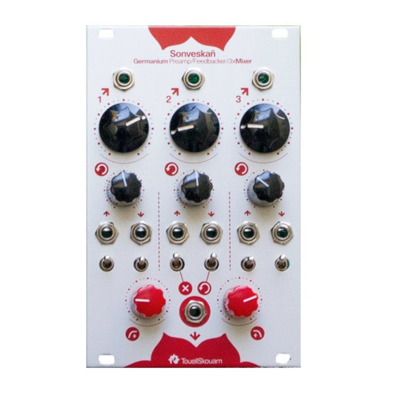
- Page 5 Sonveskan – Build Document V2 6. Next, turn the PCB over to the Pots side, and place but don’t solder yet the 10 x jack sockets and 6 x switches. Once in place fit the panel again and add some nuts to the jacks and switches to hold them in place.
- Page 6 Sonveskan – Build Document V2 7. Finally you can fit the knobs and power cable. The default/recommended starting position for all trimmers on the back of the PCB is in the middle position, they can then be adjusted to taste if desired.
Need help?
Do you have a question about the Sonveskan and is the answer not in the manual?
Questions and answers