Table of Contents
Advertisement
Quick Links
Advertisement
Table of Contents

Summary of Contents for K&M DS400
- Page 1 K&M Technologies LTD User’s Manual...
-
Page 2: Table Of Contents
Contents: Preface..............................2 Precautions:............................2 Installation Place..........................3 Power Supply ............................3 Ultrasonic Welding Principle ......................3 Pictures Of Machine.........................5 Power supply/connection ports ....................7 8. Port Connections ..........................12 8.1 Control Input port ........................12 8.2 Working Status Output Port .....................13 8.3 Analog Quantity Input/Output Port..................14 8.4 Communication Port........................14 8.5 Communications Ports for Human-Machine Interface........... -
Page 3: Preface
1. Preface Dear users, Thank you for using KnMTech ultrasonic systems, a smart, digital control ultrasonic power supply developed by our company. Before using this product, please read this manual carefully and be familiar with the operation regulations and parameter scopes. Only Professional technicians or trained personnel can commission or maintain this product. -
Page 4: Installation Place
The generator shall be installed in correct direction to assure firmness without loosening. Power supply specs must meet the demand of the generator. Professional personnel shall be in charge of the repair or maintenance if any of following happens: After turning off the power: When any liquid or metal or conductive material goes into the generator;... - Page 5 Actuator Pressure Sensor Converter Booster Welding horn Product Upper Part Product Lower Part...
-
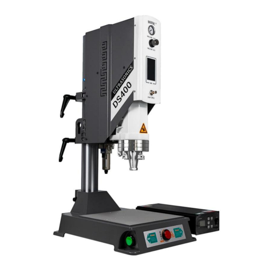
Page 6: Pictures Of Machine
6. Pictures Of Machine Pressure gauge Machine Column Pressure adjuster Fixation handle Human-machine interface Fixation handle One-way throttle valve Converter installation flange Working table... - Page 7 Leveling screw Limitation screw Filter cup Signal plug...
-
Page 8: Power Supply/Connection Ports
7. Power supply/connection ports 7.1 Power supply Power supply: AC 220V 50/60HZ Grounded 3-core cables shall be used to connect with generator. Power supply fuse is inside the generator. When it is needed to replace the fuse, the generator case has to be opened. Note: The input power must be disconnected before replacing the fuse. - Page 9 B: RF-: connect to transducer “-” port Note: Please use shielded wire to connect, withstand voltage≥2000V 7.3 Input/Output control interface (C1, C2, C3) 7.3.1 C1 port 1: COM_24V: 24V power output common port 7: AUX_3: Auxiliary port 3 input 2: READY: Ready to output 8: AUX_2: Auxiliary port 2 input 3: Mvt: Cooling or Cylinder movement output...
- Page 10 7.3.4 Input/output control interface (DB25) 14 15 16 17 18 19 20 21 22 23 24 25 10 11 12 13 7.4 Power Supply Connection Ports/Outer Control Input/Output Ports Name Status Function description C1_10 Start US start up (Note 1) C1_9 AUX_1 In Standard mode: US searching;...
- Page 11 C1_1 COM_24V Common port of output ports C3_1, 24V output positive pole (24V/1A) (Note 8) C3_2 External control C3_3, power supply 24V output negative pole (Note8) C3_4 C2_1 A0_10V Amplitude control Amplitude control input 0-10V (10-100%) C2_2 P0_10V Power output Power output 0-10V(10-100% rated) C2_3 FREQ...
- Page 12 Note4: In the Mode of STANDARD, and select PLC as the IO type, before start, this port amplitude will be switched to Shake-off amplitude (Amplitude Segment C) . Select “Key” as the IO type, and select “Grounding” as the work mode, this port is used as Grounding Input.
-
Page 13: Port Connections
8. Port Connections 8.1 Control Input port Control mode PLC output port Press Relay external control Generator inside circuits... -
Page 14: Working Status Output Port
8.2 Working Status Output Port Attention: The maximum driving current for 24V power supply input is 1A. Signal cables shall be screened type with diameter ≥0.3mm2, length shall not exceed 6 meters. -
Page 15: Analog Quantity Input/Output Port
8.3 Analog Quantity Input/Output Port Attention: analog input and output ports shall be equipped with insulated switching circuit, and the frequency port is 3.3V/10mA electrical level output. 8.4 Communication Port Attention: RS485 communication port shall be insulated and the twisted-pair wire shall be screened in strong interference place. -
Page 16: Modbus Protocol
9. MODBUS PROTOCOL(MODBUS_RTU,8/N/1,) 9.1 01H function code:Reading coil status IP type:0x,IP scope 0x0--0x5. 0x0:US working 0x3:Horn Adjustment 0x1:Frequency search 0x4:Trigger calibration 0x2:US test 0x5:Clear count to zero 9.2 02H Function code:Reading input status IP type: 1x, scope:1xX1000-1xX1015 1x0: Run status 1x8: data error 1x1: trigger cycle data reading 1x9: suspected bad quality... -
Page 17: Communications Ports For Human-Machine Interface
4x6: Delay time 4x17: upper limit of time for quality calibration 4x7: US time 4x18: lower limit of energy for quality calibration 4x8: US energy 4x19: upper limit of energy for quality check 4x9: grounding hold time 4x20: protection sensitivity 4x10: cooling or holding time 4x21: slow start speed 4x22: Energy stop speed... -
Page 18: Power Supply
IP type: 0x, scope: 0x0-0x15 See details for 01H function code. 9.6 06H function code: pre-written single register (support 10H function code) IP type: 4x, scope: 4x0-4x33. See details for 03H function code. 10 Power supply Model DS400 Power 4200W 3000W 2200W 1200W 1000W... -
Page 19: Version Information Page
Password keyboard: the password input keyboard has blue backboard with numbers, backspace, clear, ESC and ENT keys. Parameter keyboard: Parameter keyboard has a green backplate with numbers, backspace, CLR (or+/-),ESC and ENT keys. 11.2 Version Information Page This page is a default display page when you start the machine. Click any area on this page or just wait for 6s without any action, it will go to weld record page. -
Page 20: Main Page
11.3 Main Menu Main Menu is the Menu page-click the corresponding button to enter the corresponding page. Password to each page is: Protection function: 1962 Amplitude calibration: 8080 Factory setting: 2005 11.4 Welding record page This page displays the welding record, welding power and data management. Note: Shut down the machine 40s later after the welding done to prevent the loss of the welding data. -
Page 21: Trigger Preparation Page
11.4.1 Data Management CLR:Counting starts from 1, (not recoverable) and the data in the record table will not be deleted. Delete record:Delete data in the record table (not recoverable), the counting number cannot be changed. Data export: Plug in a USB flash disk, click this button and the history data in the table and scanned data will be exported to the USB flash disk. -
Page 22: Parameter Setting Page
11.5.1 Functions and Parameter Ranges Trigger mode selection: 1 Delayed trigger: Vibration will be delayed 0-10S. 2 Pressure trigger: External pressure switch Frequency tracking: to search real-time frequency (short press type, turns into green while working) Sonic testing: ultrasound function testing (long press type, turns into green while working) Trigger base:when starting it, the machine head goes down to the trigger position and gives out ultrasound and returns automatically. - Page 23 II. Segmentation:double amplitude modes, Amplitude Segment/Stage A and Segment/Stage B and the proportion of Segment A can be displayed. Setting scope: Segment A: same as Fixed mode; Segment B: 10-100%; Stage A proportion: 10-100%. Note:Segment B proportion will not be displayed, because Segment B proportion is “100%-Segment A proportion“...
-
Page 24: Qa Management Page
11.7 QC Management Page Through this interface, you can turn on/off the corresponding quality management switch and set the quality monitoring range. Time Min:0-Max/S. Time Max:Min-10/S. Energy Min:0-Max/J. Energy Max:Min-60000/J. Note:When the Min. Value is Zero, please set the Max. Value first. 11.8 Protection Function Page This page is to set the corresponding parameter, password is: 1962. -
Page 25: Factory Setting
11.8.1 Function and Parameter Range Low start speed: 10-2000mS. The value is bigger, the slow start time is longer. For those welding tools that are not easy to vibrate, this value can be increased properly. Phase lock speed:high speed, quick speed, medium speed, low speed, phase lock rate. -
Page 26: Amplitude Calibration
11.9.1 Factory setting page Start mode: key, PLC, safe Language: Chinese, English 11.10 Amplitude calibration Click Amplitude Adjustment to enter into this page. The password is “8080”. Commissioning steps for constant welding: 1. Select constant welding function and adjust it; 2. -
Page 27: Trouble Shooting
12. Trouble Shooting Ⅰ. Faulty communication Causes: Communication cables are not connected soundly; Communication chips on the control board damaged; Power source is not stable. Solutions: Check communication cables connection and plugs; Change the control board; Turn on the machine again to reset. Ⅱ.Function is limited Causes:... - Page 28 Ⅳ.Over-heated Causes: Radiation fan damaged or the wind channel is blocked; Welding horn impedance is too high, resulting in extremely high output power. Solution: Change cooling fan and check the hot wind channel; Check welding horn and start ultrasonic generator to see if the impedance is too high.
- Page 29 Check the welding horn, start ultrasonic system to judge if the horn impedance is normal. Ⅶ.Overload Power Causes: Output power exceeds the allowed power scope. Solutions: Press RESET button to search frequency; Decrease amplitude or reduce the load (such as to reduce the air pressure); Change to higher power ultrasonic generator.
-
Page 30: Quality Guarantee
Impedance of welding horn exceeds allowed scope; During ultrasonic test, the load is too high(for example, test starts when the welding horn presses on the workpieces). Solutions: Press RESET button to re-search frequency; Check the welding horn and revise it; Conduct ultrasonic test without load;... -
Page 31: Additional Information
Damage due to falling down or moving with violence after purchase; Using our equipment in the environment that does not confirm with the requirement in this user’s manual, which results in aging of the components or other malfunction; Foreign materials go inside the machine (such as bugs) , which results in the damage of the machine;...
Need help?
Do you have a question about the DS400 and is the answer not in the manual?
Questions and answers