
Subscribe to Our Youtube Channel
Related Manuals for Weco 5K3-XP-EMEA


Summary of Contents for Weco 5K3-XP-EMEA
- Page 1 WECO 5K3-XP-EMEA Installation and User Manual WECO 5K3-XP EUROPE VERSION NOT FOR USA AND CANADIAN MARKET LOW VOLTAGE & HIGH VOLTAGE...
- Page 2 Do not short the battery terminals as this may cause fire or explosion. Do not use charging devices, cables, connectors, fuses, switches not approved by WeCo. The battery and its connections such as cables, switches, fuses, bus bars etc. they must be inspected, cleaned, tightened every three months or whenever necessary also in consideration of the environmental conditions and/or stress of use of the system.
-
Page 3: Table Of Contents
WECO 5K3-XP-EMEA Contents Statement: ..........................6 Preface: ............................. 7 Declaration: ..........................7 System Design ........................8 Battery Operation ........................8 Storage ..............................8 Temperature ............................. 8 Depth of Discharge (DoD) .......................... 8 Charging ..............................9 Warranty ..............................10 Product Overview ........................11 Symbols Used .......................... - Page 4 WECO 5K3-XP-EMEA 1.4 Battery Terminal Function Definition ....................28 1.5 Out of the Box Pre-Operational Check....................29 SECTION 2 - LOW VOLTAGE CONFIGURATION ................30 2.1 Product Introduction .......................... 30 2.1.1 Identifying the Individual Module ......................... 30 2.1.2 Accessory List (Standard Kit 120A Single Module LV) ..................... 31 2.1.3...
- Page 5 Stand-Alone Battery Front Panel Control * FORCED CHARGE* ................82 HIGH VOLTAGE INVERTER COMPATIBILITY ................. 84 DRY CONTATS SETTINGS ......................84 3.10 WECO BMS - LOW VOLTAGE PC SOFTWARE for 5K3-XP .............. 87 3.11 WECO BMS - VOLTAGE PC SOFTWARE for 5K3-XP ..............92...
-
Page 6: Statement
WECO 5K3-XP-EMEA Statement: The information and guidance contained in this manual is related to the WECO 5K3-XP Stackable model of battery. This manual contains variuos sections: Section 2 is for LOW VOLTAGE APPLICATION Section 3 is for HIGH VOLTAGE APPLICATION In case of product upgrades or other reasons, this document will be adjusted accordingly. -
Page 7: Preface
You can request technical support from service@wecobatteries.com. WeCo offer two types of warranty on its products, the Manufacturing defects also called functional warranty and the performance warranty. More information can be found in this manual and on the specific warranty document available for each battery model. -
Page 8: System Design
Operating Temperature and Thresholds Many chemical reactions are affected by temperature and this is also true for the reaction that occurs in a WeCo storage battery. The chemical reaction of a lithium ion is slowed down by the lowering of the temperature of the electrolyte contained in the battery, which results in a lower capacity and a higher rate of long-term performance decay in direct proportion to the departure from the optimal temperature prescribed by WeCo. -
Page 9: Charging
All WeCo batteries produced from the beginning of 2019 can be equipped with a WiFi system for connection on WeCo Cloud, this solution ensures that they are always updated to the latest FW version notified in the APP, the Upgrade function must still be driven by the user as during the update the battery must be turned off for safety reasons and it is therefore necessary to plan this action in such a way that no inconvenience is created for users of the system. -
Page 10: Warranty
WeCo APP. From time to time, WeCo will release a new firmware to improve the functionality of the battery, if your battery will be equipped with WiFi (Paid accessory) and you will be registered on our APP, the new firmware will be visible in the APP and updatable with a simple click from your phone. -
Page 11: Product Overview
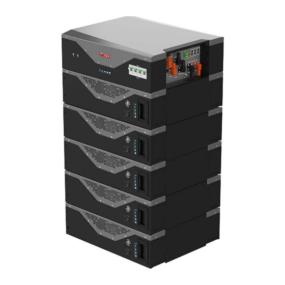
WECO 5K3-XP-EMEA Product Overview The WeCo 5K3-XP is a Stackable Battery Module with a DUAL VOLTAGE module that can be used in a Low Voltage configuration or in a High Voltage configuration. For LOW VOLTAGE (48.5-58.4 Vdc)* Configuration Refer to Section 2 For HIGH VOLTAGE (80/200-750 Vdc)* Configuration Refer to Section 3 *Voltage ranges are estimates only as they always depend on interactions with other devices and ambient conditions. - Page 12 WECO 5K3-XP-EMEA Battery Module Overview INFORMATION provides tips that are valuable for optimum installation and operation of the product. POWER RUN BUTTON SWITCH CONNECTION HUB PROTECTION PLATE UPPER REMOVABLE BRACKET WALL BRACKET LOWER REMOVABLE BRACKET REMOVABLE HANDLES STRUCTURAL FEET...
- Page 13 WECO 5K3-XP-EMEA ATTENTION: THE BATTERY IS DUAL VOLTAGE – IT CAN BE INSTALLED IN EITHER A HIGH VOLTAGE CONFIGURATION OR A LOW VOLTAGE CONFIGURATION, BUT NEVER AT THE SAME TIME. BE AWARE OF THE DIFFERENT CONNECTION METHODS AND THE SPECIFIC USE OF THE TERMINAL CONNECTORS.
-
Page 14: Safety Warnings And Notifications
CAUTION: The weight of an individual WeCo 5K3-XP Battery Module is 119 lb /54 kg. Please use original packaging and follow all safety precautions if the Battery Module is to be moved, to avoid damage to the product and personal injury. -
Page 15: Warning Statements
WECO 5K3-XP-EMEA Warning Statements Lithium Iron Phosphate (LiFEP04) Battery or Cell DANGER Hazard Statement The materials contained in this product may only represent a hazard if the integrity of the cell or battery is compromised: physically, thermally, or electrically abused. The below are the hazards anticipated under those conditions: causes skin irritation; causes serious eye irritation;... -
Page 16: General Preparation
The installation location must be on a flat level surface, in a dry, clean and protected room, away from water and humidity. Even if the mechanical installation method for the WeCo 5K3-XP Battery Modules can be considered “conceptually’’ the same for HV and LV configurations, the operator must read this manual in full. - Page 17 WECO 5K3-XP-EMEA ATTENTION: STACKABLE INSTALLATION INFORMATION The stack configuration shall be concluded by interlocking the modules by using the module feet as shown below. Always secure one module to another before completing the tower. Loosen the feet and interlock the modules by installing the feet across the two modules and using the screws of each foot.
- Page 18 REMOVE WHEN OPERATING IN STACKABLE MODE CABLES PASSAGE ATTENTION: The WeCo 5K3-XP Battery Module has two terminals for connecting the power supply. The installer must pay the utmost attention to the respective functions. LOW VOLTAGE HIGH VOLTAGE The low voltage screw terminal only supports parallel...
-
Page 19: Section 1 - Storage & Pre-Operational Procedures
WECO 5K3-XP-EMEA SECTION 1 - STORAGE & PRE-OPERATIONAL PROCEDURES 1.1 Storage - Transportation – Removing / Relocation of Batteries ✓ This Battery is considered DANGEROUS GOODS by the United Nations and must be treated accordingly. ✓ Each box comes from the factory with the below labels: ✓... - Page 20 WECO 5K3-XP-EMEA The installer approaching this battery model for the first time must understand the use and operation of its accessories. The 5K3-XP Battery Module can be equipped with an auxiliary combiner such as: • LOW VOLTAGE HUB 5K3-XP for Low Voltage configurations up to 105 batteries (7-Clusters x 15-Modules).
-
Page 21: Module Unpacking And Handling
WECO 5K3-XP-EMEA Module Unpacking and Handling The battery is always delivered in WALL mode and it is therefore necessary for the installer to make simple changes to install the STACK kit. Below are the installation phases. ATTENTION: The battery must be lifted by four persons, using the four handles. -
Page 22: Package Information And System Configuration List
1.3 Wall Mount or Stack Mount Configuration NOTE: The WeCo 5K3-XP Battery Module is shipped as standard in the wall mount configuration (in some Countries the wall mounted kit is not included and needs to be ordered separately). 1.3.1 Battery Dimensions* (Wall Bracket) - Page 23 WECO 5K3-XP-EMEA ATTENTION: The Battery Module weighs 119 lb (54 kg) and must be installed with the help of a mechanical lift, and/or by four people equipped with suitable suction cups for mechanical lifting or lifting straps. STEP 1A 100/120 cm suggested The Bracket must be installed on a flat and vertical wall capable to support the weight of the battery.
- Page 24 WECO 5K3-XP-EMEA Min 30 cm 25 cm 25 cm 25 cm 25 cm 25 cm Example of a Floor or Wall Mounted battery cluster connected with power cables and data cables. Last Module Must Have DIP 6 ENABLED Note: In a single cluster configuration, there is no need to set the DIP switch on the master battery.
- Page 25 WECO 5K3-XP-EMEA Examples of a Floor or Wall Mounted battery cluster. Cable routing behind the battery Remove the feet Secure the battery to starting from the 2 the wall using the module upward standard bracket Leave the feet of the...
-
Page 26: Stack Mount
WECO 5K3-XP-EMEA 1.3.3 Stack Mount ATTENTION: The Battery Module weighs 119 lb /54 kg (weight might vary according with the connection kit chosen) and must be installed with the help of a mechanical lift or by four people equipped with suitable suction cups for mechanical lifting or lifting straps. - Page 27 Ensure the support and/or the floor surface is adequate to support the battery load. WeCo Suggest limiting the stack to 5 modules however you can stack up to 8 if the support base/floor can support the load of the stacked cluster of 5k3 XP.
-
Page 28: Battery Terminal Function Definition
WECO 5K3-XP-EMEA 1.4 Battery Terminal Function Definition The terminal layout is shown in the following figure: Battery Terminal Wiring Definition Table Interface Name Function LV POLE + LOW VOLTAGE POSITIVE (+) Screw Terminal (10 Nm Fixing Torque Max) LV POLE -... -
Page 29: Out Of The Box Pre-Operational Check
If the LED bar is all illuminated in RED, there is a major fault and you should not attempt any further operation of the battery. Contact WeCo support at service@wecobatteries.com. There is an RS232 Operator Port which will allow you to check all parameters of the Battery Module. Full instructions on how to interface to the RS232 port can be found in this manual. -
Page 30: Section 2 - Low Voltage Configuration
2.1 Product Introduction The WeCo 5K3-XP Battery Modules can be used as an on-grid or off-grid energy storage system. It is not allowed to use this product for any purpose other than the intended purpose as described in this document. -
Page 31: Accessory List (Standard Kit 120A Single Module Lv)
WECO 5K3-XP-EMEA 2.1.2 Accessory list Low Voltage Kit (To be ordered separately). The Battery Module is packed in a carton together with accessories when ordered. When unpacking the Battery Module, be sure to check that the Battery Module and accessories are free from damage and that the correct quantities of each component are included within the carton in accordance with the purchase agreement in your country. -
Page 32: Necessary Installation Tools
WECO 5K3-XP-EMEA 2.1.3 Necessary Installation Tools Insulated Screwdriver Set Insulated Allen Key Set from 2 mm Drill + Hammer Multimeter + Current clamp to 8 mm RS232/USB + Screw Terminal (insulated) Electrician Scissors Insulated Torque Wrench Set Lifting Strap + Mechanical Lifter... -
Page 33: Low Voltage Module Wiring And Set Up
: The LV fuse is contained in the left portion of the Battery Module as shown above. The access to the fuse is restricted to authorized WeCo service personnel and the protection lid cannot be opened by anyone else. The same applies to the HV fuse. -
Page 34: Low Voltage Dip Switch Settings
All drawings and images are for reference only. Always refer to the physical product as the standard. If the manual does not match the physical product, stop all actions, remove any connections, and store them in a safe place. Call your WeCo technical service representative for assistance. -
Page 35: Low Voltage Parallel Configuration
WECO 5K3-XP-EMEA 2.3.1 LOW VOLTAGE PARALLEL CONFIGURATION The DIP switch must be set as follows to allow a single Battery Module to communicate with an inverter using CAN communications: DIP CONFIGURATION UP TO FIFTEEN MODULES IN PARALLEL From the 1... -
Page 36: Module Activation And Shutdown
WECO 5K3-XP-EMEA Module Activation and Shutdown START UP PROCEDURE The Power Switch and Run Button are located to the right of the battery terminal connections on the side of the battery chassis. The Power Switch is a mechanical switch that switches the battery ON or OFF. The Run Button is an LED button that is only enabled when the Power Switch is in the ON (1) position. -
Page 37: Low Voltage Parallel Set Up Overview
Call your WeCo technical service representative for assistance. 2.5 Low Voltage Parallel Set Up Overview 5K3-XP can be connected in parallel up to 15 modules, this process requires a full knowledge of the product. - Page 38 WECO 5K3-XP-EMEA DIP SWITCH TO BE SET 00000000 WHEN THE BATTERY IS OFF THAN NEED TO RESTART THE BATTERY CAN to Inverter To start up the system just press the Master Run Button CAN PORT 2A MASTER Port RS485B Port RS485A...
-
Page 39: Auto Id Assignment And Dip Configuration For Low Voltage Single Cluster (Parallel Connection)
WECO 5K3-XP-EMEA 2.5.1 Auto ID Assignment and DIP Configuration for LOW Voltage Single Cluster (Parallel Connection) STEP 1 ACTIVATING THE BMS FROM THE POWER SWITCH It will be necessary to activate all the batteries by switching on the POWER SWITCH (ON= position 1) -
Page 40: Single Cluster Dip And Data Connection
WECO 5K3-XP-EMEA 2.5.2 Single Cluster DIP and DATA Connection The DIP SWITCH setting for the SINGLE CLUSTER LV mode has an automatic function that assigns the single module ID in cascade. It is mandatory to connect each module in Daisy Chain connection starting from the RS485 B PORT of the master unit. -
Page 41: Parallel Battery Wiring Connections
All drawings are for reference only. Always refer to the physical product as the standard. If the manual does not match the physical product, stop all actions, remove any connections, store the batteries in a safe place and call your WeCo technical representative for assistance. Attention: For the power cable connection for high current, please refer to the specific section to see the diagram. -
Page 42: Low Voltage Single Stack Power And Data Connections (15-Modules Maximum)
WECO 5K3-XP-EMEA 2.5.4 Low Voltage Single Stack Power and Data Connections (15-Modules Maximum) Proceed with the physical installation of the desired quantity and configuration of the Battery Modules, following the installation sequences and guidelines as described in Section 1 and Section 2 of this manual. - Page 43 Attention: Illustrations shown are for reference only. Please always refer to the physical Battery Module in front of you: if the module has a different configuration to this manual, stop all activity immediately and contact your WeCo technical service representative.
-
Page 44: Led Bar Indications
WECO 5K3-XP-EMEA 2.5.5 LED Bar Indications LED Bar is located just above the RUN BUTTON and the BMS SWITCH Start Up: LED1-LED5: Green 5 seconds. Running: il LED1-LED5 become blue and the SOC level is displayed. FW UPGRADE SOC 90-100%... -
Page 45: Stand Alone Battery Front Panel Control
WECO 5K3-XP-EMEA 2.6 Stand Alone Battery Front Panel Control 2.6.1 Start Battery Press the Run Button for 2-seconds. The GREEN RUN light should come on. The Battery Module has been activated normally. 2.6.2 Shut Down Battery Press and hold the RUN Button for 5-seconds. The GREEN RUN light should go off. The Battery Module has been shut down normally. -
Page 46: Shutdown Of Parallel Batteries
WECO 5K3-XP-EMEA 2.7.2 Shutdown of Parallel Batteries Press and hold the Master Run Button for 5-seconds. The GREEN RUN light should go off immediately. The GREEN RUN lights on the sub batteries will not be extinguished immediately. The RED FAULT lights on the sub batteries’ FRONT LED bars will start flashing after ten seconds and the GREEN RUN lights will remain on. -
Page 47: Direct Parallel Connection With Certified Inverter Bms Communication (Closed-Loop)
The BMS actively monitors the voltage difference between cells or between batteries and applies the most appropriate balancing function. The balancing algorithms are based on multiple factors detected by the BMS up to 30 days earlier. These functions are only applicable with WeCo approved inverters... -
Page 48: Power Connection Of A Single Cluster
WECO 5K3-XP-EMEA 2.8 Power Connection of a Single Cluster -Double BUS BAR- ATTENTION: Both ends of the cluster must be connected with two output 50 mm2 or 75mm2 cables. Cables length shall not exceed 250cm. The suggested output cable is composed of two sets of 50 mm2 each of max length of 200cm. - Page 49 WECO 5K3-XP-EMEA Cable size verification for a cluster composed by 5 or more Battery Modules connected to the inverter with 2 sets of cables (50mm² each) for a total of 100 mm² each terminal (positive and negative). When more than one battery is connected in parallel, we suggest using a capacity reduction factor of 2% to calculate the Cluster Capacity at the first installation.
-
Page 50: Can Hub For Multi Cluster Configuration
Each battery pack and cluster must have the same voltage and firmware. All stack configurations must use the WeCo Bus Bar up to max 300Adc. Each cluster must have the same number of battery packs with the same firmware. -
Page 51: Low Voltage Inverter Compatibility List
WECO 5K3-XP-EMEA 2.10 Low Voltage Inverter Compatibility List... - Page 52 WECO 5K3-XP-EMEA 2.11 Low Voltage Inverter Battery to Inverter CAN Terminal Pin Out INFORMATION All CAN and RS485 communication cables are of the T568 type. B The CAN/BMS communication cable between battery and inverter varies depending on the inverter model.
-
Page 53: Section 3 - High Voltage Configuration
WECO 5K3-XP-EMEA SECTION 3 - HIGH VOLTAGE CONFIGURATION SERIAL CONNECTION AND SYSTEM CONFIGURATION HIGH VOLTAGE STACKABLE CONFIGURATION ATTENTION: THIS SECTION IS FOR HIGH VOLTAGE CONFIGURATION ONLY IT IS COMPULSORY TO USE THE 5K3-XP HV BOX FOR THIS CONFIGURATION HV BOX XP is not compatible with LV/HV batteries. -
Page 54: Product Introduction
WECO 5K3-XP-EMEA 3.1 Product Introduction The WeCo 5K3-XP Battery Modules can be used as an on-grid or off-grid energy storage system. It is not recommended to use this product for any purpose other than the intended purpose as described in this document. -
Page 55: Product Identification And Labels
HV BOX XP LABEL (Example) Energy Storage Systems Energy Storage Systems WeCo Srl Viale Kennedy 113-121 WeCo Srl Viale Kennedy 113-121 Scarperia e San Piero CAP 50038 (FI) Scarperia e San Piero CAP 50038 (FI) Emergency Number ITALY + 39 055-0357960 www.wecobatteries.com... -
Page 56: Hv Box Dimensions
WECO 5K3-XP-EMEA 3.1.3 HV BOX XP Dimensions 170mm 470mm 580mm HV BOX XP TYPE A/B Specs TYPE B Description Type A Dimensions 580 x 470 x 170 39.7 lb Weight lb (kg) (18 kg) Case Material Type Steel Operative Voltage (Type B) -
Page 57: Battery Module Accessory List (Standard Kit)
WECO 5K3-XP-EMEA 3.1.4 Battery Module Accessory List (LV Standard Kit) Kit Composition may be different in certain Countries, always confirm the accessories before placing the order. The Battery Module is packed in a carton together with standard accessories. When unpacking, be sure to check that the Battery Module and accessories are free from damage and that the correct quantities of each component are included within the carton. -
Page 58: Hv Box Kit (Included In The Carton Box)
WECO 5K3-XP-EMEA 3.1.5 HV BOX KIT (Included in the HV BOX carton Box) Cable Color Cable Size Cable Length Description Image 25mm2 15cm N° 1 Module to HV BOX double side fast connector, both side Red BLAC 25mm2 250cm N° 1... -
Page 59: Necessary Installation Tools
WECO 5K3-XP-EMEA 3.1.6 Necessary Installation Tools Drill + Hammer Insulated Screwdriver Set Insulated Allen Key Set Multimeter + Current clamp RS 232/USB + Screw Terminal (insulated) Electrician Scissors Insulated Torque Wrench Set Lifting Strap + Mechanical Lifter 3.1.7 Personal Protective Equipment + 1000 Vdc Insulated Tool Kit... -
Page 60: High Voltage Battery Module Wiring And Set Up
: The LV fuse is contained in the left portion of the module, the HV fuse is contained in the right portion as shown above. The access to the fuse is restricted to authorized WeCo service personnel, and the protection lid cannot be opened by anyone else. - Page 61 WECO 5K3-XP-EMEA Battery Terminal Definition table The terminal layout is shown in the following figure: Module Definition Table Interface Name Function LV POLE + LOW VOLTAGE POSITIVE (+) Screw Terminal (NO USE IN HV CONFIGURATION) LV POLE - LOW VOLTAGE NEGATIVE (-) Screw Terminal (NO USE IN HV CONFIGURATION)
-
Page 62: Hv Box Overview
WECO 5K3-XP-EMEA HV BOX Overview Power Led Run Led BREAKER 125A INFO LED BAR SUPPORT BRACKET BATTERY LINE INPUTS GREEN INPUT CHANNEL 01/02 CAN 2A/BMS... - Page 63 WECO 5K3-XP-EMEA HV BOX Terminals Definition Table HV BOX Definition Table Interface Name Function WIFI ANTENNA WiFi ANTENNA * (Optional) INPUT CHANNEL + POSITIVE INPUT FROM THE INVERTER CHANNEL 01 POSITIVE PLUG (+) MAX 50A INPUT CHANNEL - NEGATIVE INPUT FROM THE INVERTER...
-
Page 64: High Voltage Module Configuration
WECO 5K3-XP-EMEA 3.4 High Voltage Module Configuration ATTENTION: The High Voltage mode mandates that the Battery Modules must be connected in series. ATTENTION: The following table provides the possible module configurations. NO OTHER configurations are permitted. ATTENTION: Before connecting an HV inverter with the HV BOX terminal, always check the inverter input range. -
Page 65: High Voltage Dip Switch Settings
ATTENTION: All drawings are for reference only. Always refer to the physical product as the standard. If the manual does not match the physical product, stop all actions, remove any connections and store the batteries in a safe place. Call your WeCo technical representative for assistance. -
Page 66: Serial Tower Connection #1 Set-Up Of The Hv Box Can Communication Loop
WECO 5K3-XP-EMEA 3.5.1 Serial Tower Connection #1 Set-Up of the HV Box CAN Communication Loop Four batteries connected in series is the suggested minimum configuration for High Voltage operation: CAUTION After setting the DIP switches, the batteries must be restarted for the DIP switch changes to take effect. -
Page 67: Serial Battery Wiring Connections
WECO 5K3-XP-EMEA 3.6 Serial Battery Wiring Connections CAN TO HV BOX POSITIVE TO HV BOX NEGATIVE TO HV BOX CAN PORT B CAN PORT A CAN PORT B CAN PORT A CAN PORT B CAN PORT A LAST MODULE POWER CABLE CONNECTIONS MUST BE MADE IN STRICT ACCORDANCE WITH THE INSTRUCTIONS IN THIS MANUAL. - Page 68 Attention: All drawings are for reference only; always refer to the physical product as the standard. If the manual does not match the physical product, stop all actions, remove any connections, store the batteries in a safe place and call your WeCo technical representative for assistance.
-
Page 69: High Voltage Power Connections
WECO 5K3-XP-EMEA 3.6.1 High Voltage Power Connections 5K3-XP HV Box can support maximum of 16 modules (934Vdc string Voltage). Proceed with the physical installation of the desired quantity and configuration of the Battery Modules, following the installation sequences and guidelines as described in Section 1 of this manual. -
Page 70: Data Connections (Example Of 12-Modules)
WECO 5K3-XP-EMEA 3.6.2 DATA Connections (Example of 12-Modules) Step 1: Set up the DIP Switches as per the picture below. Step 2: Connect the CAN PORTS, starting from the HV Box PORT CAN A, then chain connection as shown below. - Page 71 WECO 5K3-XP-EMEA Make sure that the ground connection is not shared with other potential distributing devices and that the ground rod is not used for Neutral Line dispersion or Harmonics mitigation circuit. Use the inverter GND line CAN A CAN B...
-
Page 72: Hv Box And Battery Module Power Connection
Turn on the battery cluster as stand-alone (not connected with the inverter) • Connect the PC via RS 232 and by using the WECO XP MANAGER and identify the error if present (contact WECO for further support) • If there are no errors as stand-alone need to repeat the same procedure above by connecting the inverter to the HV BOX (see start-up process) •... -
Page 73: Single Hv Box Connection To An Inverter
WECO 5K3-XP-EMEA 3.6.4 Single HV Box Connection to an Inverter Step 1: Turn the HV Box off by switching off the MAIN BREAKER located on the right side. Step 2: Turn the Solar Inverter OFF. Step 3: Connect the RJ45 cable into the CAN PORT 2A and perform the connection as per the Inverter Manual by following the PIN layout provided below. -
Page 74: Multi Hv Box Connection
WECO 5K3-XP-EMEA Multi HV Box Connection SINGLE BRANCH CONNECTION Multi Clusters Communication Cable Connection CAN TO INVERTER SPECIAL RJ45 CABLE: ONLY PIN1 AND PIN2 (see pag. 91) ATTENTION When there are TWO HV BOX installed under the same Inverter CAN INPUT it is necessary to SET the inverter addresses inputs to identify two batteries on two separate channels. - Page 75 WECO 5K3-XP-EMEA With more than Two HV clusters it is compulsory to use the HV HUB as CAN COMBINER Multi HV Box Connection General Instructions In a Multi Cluster Connection with only one inverter CAN Connection Line, it is necessary to use the HV HUB and connect in Daisy Chain all the HV BOXES of each Cluster.
- Page 76 WECO 5K3-XP-EMEA Preconditions The cluster must be loaded in HV up to 100% shown on the inverter display. Once 100% is reached, even after the jump of SoC, it will be possible to proceed as follows. Turn off the HV BOX by acting on the disconnector...
- Page 77 WECO 5K3-XP-EMEA 3.6.5 HV BOX SHUT DOWN PROCEDURE ORDINARY SHUT DOWN PROCEDURE OF THE HV BOX To turn off the HV BOX of any cluster connected to the inverter, it is mandatory to follow the procedure. 1. Turn off the PV INPUT from the inverter by turning the DC switch of the inverter.
-
Page 78: Hv Box Address
WECO 5K3-XP-EMEA 3.7 HV Box ADDRESS... - Page 79 WECO 5K3-XP-EMEA MULTI CLUSTER CONNECTION HUB XP (VALID FOR LV or HV HUB) ATTENTION: The connection between two HV BOX connected in Daisy chain through the CAN ports must imperatively be made with a specific two-wire RJ 45 cable. The communication cable must be made by crimping only PIN 1 and PIN 2 All PINs between PIN 3 and PIN 8 must be left blank.
- Page 80 WECO 5K3-XP-EMEA 11. Wait for the complete start-up and then proceed with the same methodology for each cluster. 12. At this point, the start-up procedure is completed and the HV HUB device will initiate the control procedure of each single cluster by activating the HV HUB contactors one by one to prevent voltage spikes.
-
Page 81: Led Visual Indication Lights
Read this entire manual thoroughly to understand the correct startup and shutdown procedures for each battery configuration. As the modules are connected to the WECO CLOUD, some modifications of the of the ordinary procedure might change and could not reflect this manual. -
Page 82: Stand-Alone Battery Front Panel Control *Forced Charge
WECO 5K3-XP-EMEA Stand-Alone Battery Front Panel Control *FORCED CHARGE* 3.7.2 3.7.2.1 Start Battery Press the Power Button of the HV Box for 3 or more seconds (depends on the system status). The GREEN RUN light should come on. The HV Box module has been activated normally and the Battery Modules should come on automatically. - Page 83 ATTENTION: Each Battery Module must be recharged at the same SoC. The inspection must be done by using the WeCo RS232 and LV PC software or via BT app. This process could take some time and will require either a portable PC or handheld computer device or a mobile phone with WeCo Apps.
-
Page 84: High Voltage Inverter Compatibility
WECO 5K3-XP-EMEA 3.8 HIGH VOLTAGE INVERTER COMPATIBILITY CAN PIN DEFINITION FOR HV INVERTERS... -
Page 85: Dry Contats Settings
WECO 5K3-XP-EMEA 3.9 DRY CONTACTS SETTINGS The battery is equipped with dry contacts that allows to interact with external devices, other than the inverter to which they are connected. This contact, referred to as DO2+ and DO2-, is accessible via the green connector located next to the battery DIP switches. - Page 86 WECO 5K3-XP-EMEA The dry contact DO2 (Digital Output 2) is a normally open contact, which can be set to close within a user- defined range through the setting of the closing and opening threshold. Set the % SoC below which the...
-
Page 87: Weco Bms - Low Voltage Pc Software For 5K3-Xp
RS232 Serial Converter with 232-RJ45 Plug WeCo Monitor PC-SOFTWARE PIN OUT RS232 CONVERTER STEP 1. Download the latest version of the WeCo BMS PC software at www.wecobatteries.com. Enter the password: 1010. Click: Operator Access to run the program in -Operator Mode- Password: 1010 STEP 2. - Page 88 WECO 5K3-XP-EMEA STEP 3. Connect the RJ45 plug from the RS232-USB Converter to the Operator Port of the Battery Module. Th moduel must be switched on. The Operator Port is located on frnt panel. nd PRESS RUN Turn On The...
- Page 89 WECO 5K3-XP-EMEA STEP 5. When the communication is established between the PC and the Battery Module, the PC software will display a page like the one below: If more than one battery is connected in parallel, all the information will be displayed on this page.
- Page 90 WECO 5K3-XP-EMEA STEP 7. FIRMWARE UPGRADE To update the firmware to a more recent version, it is necessary to download the latest version of the WeCo BMS software www.wecobatteries.com and install it from the software as indicated. ATTENTION FOR XP BATTERIES SELECT ONLY XP-FIRMWARES (.bin) DO NOT USE LV/HV FIRMWARE (.hex)
- Page 91 WECO 5K3-XP-EMEA 3.11 WECO BMS - HIGH VOLTAGE PC SOFTWARE for 5K3-XP Use an Opto-Isolated RS232-USB Converter for the connection between PC and HV BOX. STEP 1. Connect the RJ45 Port with the Operator Port located in the front of the HV BOX.
-
Page 92: Weco Bms - Voltage Pc Software For 5K3-Xp
WECO 5K3-XP-EMEA STEP 3. SYSTEM INFORMATION From this page it is possible to view the modules that make up the system. It is also possible to monitor the voltage and current status of each individual module and any warnings or alarms. - Page 93 WECO 5K3-XP-EMEA MOBILE Bluetooth APP Install the WECO App by downloading it from the App Store / Google Play Search For: WeCo WiFi To get the Remote Monitoring Search For: WeCo Bluetooth To get the Local APP Android WiFi Android Bluetooth...
- Page 94 WECO 5K3-XP-EMEA MOBILE APP GENERAL OVERVIEW + FIRMWARE UPGRADE Operator Access Password 1010 is required for Enable the Blueetoth function Private User To Change BMS Protocol press here Running Alarms or Warns will appear here Software upgrade...
- Page 95 ATTENTION, BATTERY ALARMS/WARNS In the presence of any alarm / warns on both the battery and the inverter, the user must switch off and disconnect the power connection between the batteries and the inverter. The battery must be inspected immediately with an authorized WeCo technician or send the battery to WeCo for an accurate check.
- Page 96 WECO 5K3-XP-EMEA WeCo srl Viale Kennedy 113-121 Scarperia Firenze Italia www.wecobatteries.com All data subject to change without notice. Actual product color may vary. No part of this document can be copied r reproduced, electronically or mechanically, without written permission from the company...
Need help?
Do you have a question about the 5K3-XP-EMEA and is the answer not in the manual?
Questions and answers