Table of Contents
Advertisement
Quick Links
Advertisement
Table of Contents

Summary of Contents for Soundtronics M2 SYNTH 192
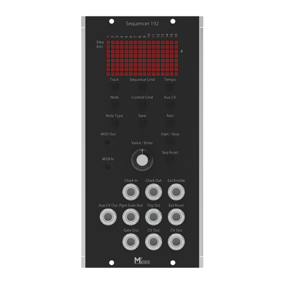
- Page 1 SOUNDTRONICS M²SYNTH User Manual 192 192 Programmable Sequencer...
- Page 2 192 Programmable Sequencer Soundtronics Ltd Unit 29 Webb Ellis Business Park Woodside Park Rugby Warwickshire CV21 2NP www.m2synth.com www.soundtronics.co.uk...
-
Page 3: Table Of Contents
T able of Contents Overview ................2 Features ................3 Panel Controls ..............5 Basic Operation ..............6 Sequence Commands ............11 Control Commands ............23 Live Editing ................ 28 External Controls ..............30 MIDI Controls ..............32 Using the 192 Sequencer ........... 33 Index .................. -
Page 4: Overview
Chapter Overview The 192 Sequencer is one of the many modules from the Soundtronics modular analogue synth – the M²Synth. While most modules require very little introduction, the 192 Sequencer has features that many users may be unfamiliar with. This manual describes each of the individual features enabling you to get the most out of the sequencer. -
Page 5: Features
Chapter Features Main features and specifications of the 192 sequencer. Size Height 5U (222.25mm) Width 2U (88.9mm) Depth 40mm behind panel, 63mm overall Electrical Supply voltage +/-12V Supply current +62/-6mA – to be confirmed Digital outputs 5V ... - Page 6 Notes User selectable from C to G which covers all 128 MIDI notes of over 10 octaves 6 Note lengths demisemiquaver to semibreve which equates to 1 clock pulse to Tempo 10 to 240 BPM where 1 beat is a crotchet Sequence Commands ...
-
Page 7: Panel Controls
Chapter Panel Controls Press to select sequence command Press to select track to load Press to adjust tempo Press to select control command Press to adjust step auxiliary voltage Press to select note Press to select note or Press for a rest (no gate) rest length Save current track Start / stop sequencer... -
Page 8: Basic Operation
Chapter Basic Operation On first power up, Step LED The sequencer will be stopped on step 1, default note C4 and track 00 displayed. Note that at this stage, the sequencer will boot up with an empty sequence with default values in its working memory, track 00 has not yet been loaded. - Page 9 running and the last step reached will remain displayed. Press Reset and the sequencer will revert back to step 1. Step Selection Now using the Value control knob, rotate it clockwise and the step LED will move towards step 16 and anticlockwise to move it back towards step 1. Moving clockwise past step 16 goes to step 1 of bank 2 (step 17).
- Page 10 Step 49 is indicated by all step LEDs being on. Press Reset to go back to step 1 or use the Value control. Note Selection Now that you can select any of the 48 steps, let’s move on to choosing a particular note for each step.
- Page 11 10.5833 Note type (length) Each note can have its length set by using the Note Type button. Hold the Note Type button in and using the Value control allows the selection of the note type from demisemiquaver to semibreve. The mnemonics for these are displayed from ÷8 to x4 based on their relationship to a crotchet.
- Page 12 Track Selection, Loading and Saving Up to now, we have only been using the working memory, powering down the module will result in a loss of the sequence. In an attempt to keep menu diving to a minimum and keep things simple to use, there is no copy function. This means that if the intent is to save the sequence once created, the track number should be selected first.
-
Page 13: Sequence Commands
Chapter Sequence Commands Any step can hold a sequence command in place of a note to direct the sequencer to do something other than simply step onto the next step. The sequence commands available when the sequencer is stopped are: Sequence reset Sequence stop Sequence reverse... - Page 14 The display when selecting the Reset command is RST. No additional value required. After selection, in place of the note, the display will show RS. Sequence Stop Command operation: When the sequence reaches the Stop command step, the sequence immediately resets to step 1 and stops running. The display when selecting the Stop command is STOP.
- Page 15 Sequence Reverse Command operation: When the sequence reaches the Reverse command step, the sequence carries on running but downwards until it reaches step 1 when it will begin stepping upwards again. For example, if the Reverse command is at step 6, the sequence will continue from step 4. In practice the sequence would look like 1-2-3-4-5-4-3-2-1-2-3-4-5-4 etc..
- Page 16 Goto Bank Command operation: When the sequence reaches the Goto Bank command step, the sequence immediately continues from the first step in that bank (step 1, 17 or step 33). The bank can be before or after the current bank. The display when selecting the Goto Bank command is BAN>.
- Page 17 Goto Track Command operation: When the sequence reaches the Goto Track command step, the sequencer will load the destination track and continue running from step 1 of this new track. Note: make sure the initial track with the Goto Track command is saved before running otherwise any changes made to it will be lost.
- Page 18 Loop Command operation: When the sequence reaches the Loop command step, the sequencer will continue from the first step in the current bank. For example, if the Loop command is contained within a step in bank 3, then the sequence will continue from step 33. The display when selecting the Loop command is LOOP.
- Page 19 After releasing the Sequence Cmd button, the display shows the value screen to select the number of repeats 01-99. Press the Value control knob to enter the number of repeats. After selection, in place of the note, the display will show <<. Transpose Command operation: When the sequence reaches the Transpose command step, the sequence will continue playing from the step following the Transpose...
- Page 20 The display when selecting the Transpose command is TRAN. An additional value is required for the number of repeats to be executed in the range down 19 to up 19. After releasing the Sequence Cmd button, the display shows the value screen to select the transpose value.
- Page 21 After selection, in place of the note, the display will show TR. Goto Step Command operation: When the sequence reaches the Goto command step, the sequence will continue playing from the destination step associated with the Goto command. The display when selecting the Goto command is GOTO. An additional value is required for the destination step in the range down 01 to 48.
- Page 22 After selection, in place of the note, the display will show GO. Hold Step Command operation: When the sequence reaches the Hold command step, the sequence will pause for a period of time defined by the associated value in crotchets. The display when selecting the Hold command is HOLD.
- Page 23 After selection, in place of the note, the display will show HO. Gate on Time Command operation: Unlike the preceding sequence commands, the Gate on Time does not replace a note or alter the sequence flow. The Gate on Time defines how long the Gate Out pulse is active for while the sequence is playing that step.
- Page 24 After releasing the Sequence Cmd button, the display shows the value screen to select the gate on time in terms of percentage 05-95. Press the Value control knob to enter the percentage. After selection, in the display will revert back to showing the note number. If all steps are required to have a different to the default but common gate on time then select step 49.
-
Page 25: Control Commands
Chapter Control Commands There are three types of Control commands that do not replace a step note but provides additional output functionality. Control commands have no associated value to enter except for Auxiliary CV. The control commands available when the sequencer is not running are: Primary commands ... - Page 26 However, with the sequencer stopped it is possible to view what steps in the current bank have associated Control Commands. To view what steps have associated commands, stop the sequencer running and press the Value control knob. In the image above, the positions of the control commands are shown in row 2 of the display at steps 4, 8 &...
- Page 27 After releasing the Control Cmd button, the display reverts to the usual display showing track number and note number. Programmable Gate On / Off The display when selecting the Programmable Gate On is GAT+. This command simply turns on the Pgm Gate Output and it stays on until a Programmable Gate Off command is executed.
- Page 28 Ratcheting Ratcheting is where instead of one gate pulse per step, multiple gates pulses are generated. This technique has been used and popularised by such bands as Tangerine Dream. It is possible to have up to 32 gate pulses per step. However, as the step size gets shorter and the tempo gets faster, having multiple gate pulses can get rather crowded and having gate pulses every few mS or even quicker can get impractical.
- Page 29 After releasing the Control Cmd button, the display reverts to the usual display showing track number and note number. Auxiliary CV The third type of Control Command is for setting an auxiliary CV. An auxiliary voltage CV can be set for each step in addition to a primary or secondary control command.
-
Page 30: Live Editing
Chapter Live Editing Modular synths are all about hands on and interaction. While the 192 Sequencer can be fully configured before running the sequence, being able to make adjustments while it is playing is an important feature and aligned with that of the traditional analogue sequencer. - Page 31 Note Note Type Rest Type Sequence commands: Reset Stop Reverse Loop Gate on Time Control Commands: None Programmable Gate On Programmable Gate Off Ratcheting Auxiliary CV The following controls are also active while a sequencer is running. Track selection Save Stop Reset Tempo (hold Tempo button while using the Value control to set the tempo...
-
Page 32: External Controls
Chapter External Controls Integrating the 192 Sequencer within your modular is of course through the jack sockets. There are 10 sockets: CV output sockets provide a duplicate output of the voltage representing the note being played. This CV is typically but not exclusively sent to the VCO(s) and to a VCF for filter tracking Gate out socket is used to trigger an ADSR envelope generator which in turn is used for a VCA or VCF. - Page 33 Reset input socket responds to the rising edge of a pulse. On the rising edge, the sequencer resets and continues stepping from step 1. Enable input socket responds to a change in start of this signal. If the sequencer is stopped, a positive going signal will start the sequencer running from the current step.
-
Page 34: Midi Controls
Chapter MIDI Controls The 192 Sequencer is primarily intended for an analogue synth via its CV and gate outputs. It does however have some basic MIDI functionality for completeness. As each note plays, a note on signal is transmitted over the MIDI out interface on channel 1 while the gate signal is active and note off when the gate turns off. -
Page 35: Using The 192 Sequencer
Chapter Using the 192 Sequencer The previous chapters described the functionality and features of the sequencer. How the sequencer is used is down to the user. Whether you use it as a blank canvas and create your composition from scratch while it is playing or program in a melody from a musical score such as Tangram by Tangerine Dream: End of section... - Page 36 End of 1 Measure <<:|| Repeat 1 Measure ||:>> Begin Repeat Once <<:|| Repeat 3 Measure ||:>> Begin Repeat Once <<:|| Repeat 5 Measure ||:>> Begin Repeat Once <<:|| Repeat 7 Measure Keep playing above Once This is not the only way of entering this sequence in as measures 7&8 are a repeat of 3&4 but there is little to be gained in this instance of making it more compact as there is plenty of spare capacity.
-
Page 37: Index
Index Auxiliary CV, 27, 30 Note type (length), 9 Clock in, 30 Programmable Gate off, 23 Clock out, 30 Programmable Gate on, 23 Control Commands, 4 Programmable Gate On / Off, 25 CV output, 30 Programmable gate out, 30 CV output voltage, 8 Ratcheting, 23, 26 Edit LED, 28 Repeat begin, 4, 23...
Need help?
Do you have a question about the M2 SYNTH 192 and is the answer not in the manual?
Questions and answers