Subscribe to Our Youtube Channel
Summary of Contents for unicore UM620N
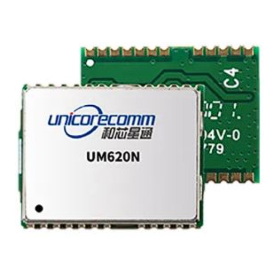
- Page 1 HARDWARE REFERENCE DESIGN WWW.UNICORECOMM.COM UM620N Automotive Grade Dual-frequency Multi-GNSS Positioning Module Copyright© 2009-2023, Unicore Communications, Inc. Data subject to change without notice.
- Page 2 This manual does not represent, and in any case, shall not be construed as a commitments or warranty on the part of Unicore with respect to the fitness for a particular purpose/use, the accuracy, reliability and correctness of the information contained herein.
- Page 3 UM620N V1R0 Hardware Reference Design Contents Reference Circuit Using an Active Antenna ..............1 Reference Circuit Using a Passive Antenna ..............2 Recommended BOM ....................3...
- Page 4 1 Reference Circuit Using an Active Antenna The supply voltage for VCC is 2.7 V ~ 3.6 V Ground all GND pins of the module Connect the RF_IN signal to the antenna; note the 50 Ω impedance matching ...
- Page 5 UM620N V1R0 Hardware Reference Design 2 Reference Circuit Using a Passive Antenna When using a passive antenna, a low noise amplifier should be added between the antenna and the RF_IN of the module in order to ensure the performance of the system.
- Page 6 3 Recommended BOM Component Order No. Manufacturer RS-232 TRS3122ERGER Transceivers MXDLN14TP MAXSCEND...
- Page 7 和芯星通科技(北京)有限公司 Unicore Communications, Inc. 北京市海淀区丰贤东路 7 号北斗星通大厦三层 F3, No.7, Fengxian East Road, Haidian, Beijing, P.R.China, 100094 www.unicorecomm.com Phone: 86-10-69939800 Fax: 86-10-69939888 info@unicorecomm.com www.unicorecomm.com...


Need help?
Do you have a question about the UM620N and is the answer not in the manual?
Questions and answers