Table of Contents
Advertisement
Quick Links
Quick Installation Guide
Industrial Compact
LTE/ WLAN Router
AP224
www.avcomm.us
・Overview
The LTE, WLAN router AP224-WLAN+LTE and Wireless LAN
AP AP224-WLAN are designed for industrial and smart city
applications.
The AP224 router supports LTE to WLAN
redundancy and LTE/WLAN auto
continuous
connections.
To
safeguard
security features such as Firewall, OpenVPN, GRE tunnel
are supported. The embedded MQTT and RESTful API
enables instant public cloud integration such as AWS or
Azure.
Model Name
Description
Industrial Wireless IIoT Field Routing
Gateway,4FE, 802.11b/g/n WLAN, LTE-E,
AP224-WLAN-
2SIM( without antenna),4-port 10/100M
LTE
RJ45,1 WLAN+3 LAN/4 LAN, Redundant
2×SIM
Industrial Wireless IIoT Field Routing
Gateway,4FE, 802.11b/g/n WLAN(without
AP224-WLAN
Antenna),4-port 10/100M RJ45,1 WLAN+3
LAN/4 LAN, Redundant 2×SIM
*LTE-AU/LTE-U/LTE-CN or other region by
request
*GPS support by request
*Also apply to AP224
AVCOMM Technologies, Inc
・Package Checklist
•
1 x Product Unit
•
1 x 2-pin Removable Terminal Connector
•
2 x LTE Antenna, Black + 2 x Wi Fi Antenna, White (by model)
•
1 x DIN rail kit
•
1 x Quick Installation Guide
Optional Accessory (for detailed information please refer to the
Datasheet)
・Installation
SIM Card Slot
Warning: Be careful when install
the SIM Card, wrong installation
procedure will cause damage.
Make sure the SIM Card is
facing the correct position.
Wall mount
Two wall mounting plates are installed
at the left and right side of the switch.
Use the two hook holes at the corners
of each wall mounting plate or the
middle hole to hang the switch on the
wall them then screw tightly.
DIN Rail mount
offload to guarantee
For the DIN Rail mount, attach the DIN Rail Clip (
cybersecurity,
mount plates.
Grounding Screw
The grounding screw is located on the bottom side
of the router. For avoiding system damage by noise
or electric shock, establish a direct connection
between the ground screw and the grounding
surface prior to connecting devices.
No support negative power structure install
Warning: If power positive connects with device ground, it will
short the power system and damage the device..
Wiring the Power Input (9~30V)
1)Insert the positive and negative wires into the V+
and V- contact on the terminal block connector.
2) Tighten screws when the wire is connected.
3)Connect the power wires to suitable DC Switching
type power supply.
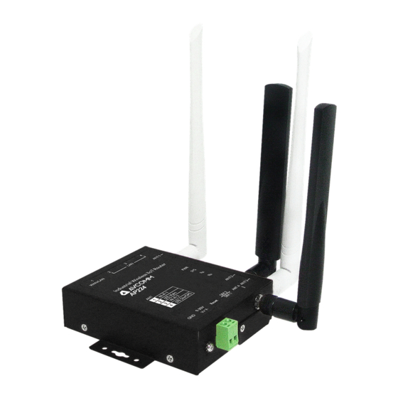
・Appearance
AP224
System LED
・1 x Power
・1 x System Status
・2 x Radio Status
LED (Ra/Rb)
Grounding Screw
SIM 2
SIM 1
Integrated Power Connector
・1 x 2-pin terminal block for
9~30V power input
Wall Mount Clip
Top Panel
ANT 1
DK-D2-2)
to the two wall
Bottom Panel
Grounding
Grounding Screw
Address: 333 West Loop North, Suite 460 Houston, TX 77024,United States
V+ V-
Ethernet Network
・4-port 10/100M RJ45
・1 W AN + 3 LAN, or 4
LAN
Wall Mounting
Clip (Both Sides)
ANT 2
ANT 3
4 x SMA Antenna Socket
SIM Card
・2x SIM for redundancy
ANT 4
4
1
3
2
Reset
ANT 4
Screw
Button
ANT 3
Power
SIM Card slot
Connector
ANT 1
Advertisement
Table of Contents

Summary of Contents for AVCOMM AP224
- Page 1 ・Overview wall them then screw tightly. ANT 1 The LTE, WLAN router AP224-WLAN+LTE and Wireless LAN AP AP224-WLAN are designed for industrial and smart city applications. The AP224 router supports LTE to WLAN DIN Rail mount redundancy and LTE/WLAN auto...
- Page 2 • After you click Login, a page that request to change the password will AVCOMM reserves the right to make changes to this QIG or to the appear. Then you can enter the new password. Click Submit to apply product hardware at any time without notice. It is the user’s...
Need help?
Do you have a question about the AP224 and is the answer not in the manual?
Questions and answers