Table of Contents
Advertisement
Quick Links
Advertisement
Table of Contents

Related Manuals for Roadmaster AddaBRAKE 8800

Summary of Contents for Roadmaster AddaBRAKE 8800
- Page 1 Owner’s Manual Entire contents of manual must be read by owner Part number 8800 Towing and Suspension Solutions ROADMASTER, Inc. • 6110 NE 127th Ave • Vancouver, WA 98682 800-669-9690 • fax 360-735-9300 • roadmasterinc.com 85-3476 rev. 02 08/08 © 2008 ROADMASTER, Inc.
-
Page 2: Safety Definitions
WELCOME TO THE ROADMASTER FAMILY! his manual has been prepared to acquaint you with the installation and operation of your AddaBRAKE, and to provide you with important safety information. Read your owner’s manual cover to cover. Understand how to install and operate your AddaBRAKE, and care- fully follow the instructions and safety precautions. Your AddaBRAKE has a one-year limited warranty. To qualify for your warranty, fill out and return the enclosed product registration card within 30 days of purchase. As a bonus, we’ll extend your warranty to a total of two years at no additional cost, if we receive the product registration card within 30 days of purchase. We thank you for your patronage and greatly appreciate your discerning taste. -
Page 3: Table Of Contents
Not for use on older vehicles without power ROADMASTER expressly disallows any and all brakes. AddaBRAKE is designed to work with ve- claims relating to tire damage, brake damage, or hicles that have a power brake system (even though any other damage to vehicles with ‘active’... -
Page 4: Components
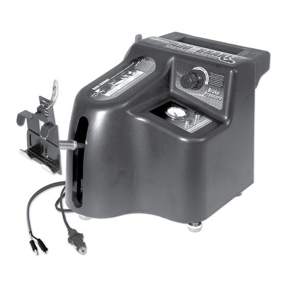
COMPONENTS part part number description number description 1 9329 ....brake pedal clamp 11 650906....AddaBRAKE wiring harness 2 n/a .......air cylinder shaft 12 650900....break away wiring harness 3 n/a .......pressure gauge 13 8602 ....break away cable 4 n/a .......regulator control knob 14 650898....break away switch 5 n/a .......air relief button 15 650906-01 ...brake signal wire 6 n/a .......test button 16 300065-00 ...motorhome monitor LED 7 650996....adjustable seat pad 17 9325 ....audio signal circuit board (handle assembly) -
Page 6: Before You Begin The Initial Installation (Installer's Checklist)
Before you begin the initial installation… 1. ALWAYS CHECK THE ROADMASTER WEB SITE — cause intermittent operation. www.roadmasterinc.com — for vehicle-specific informa- If the socket is corroded or damaged, you can in- tion. Select ‘Vehicle-Specific Info,’ enter the motorhome stall the optional 12-volt outlet kit (part number 9332). and towed vehicle make, model and year, then select When installed, this kit will provide constant power to ‘Braking Systems.’ AddaBRAKE. 2. If the battery must be disconnected for towing, a 12-volt outlet kit (part number 9332) and a stop light switch must be installed. ROADMASTER manufactures If the towed vehicle has a single 12-volt outlet stop light switch kits for a number of vehicles; to... - Page 7 ROADMASTER manufactures stop light switch kits for a number of vehicles; to see if one is available for any specific vehicle, visit www.roadmasterinc.com and select ‘Vehicle-Specific Info,’ enter the vehicle make, model and year, then select ‘Braking Systems' and scroll down the page.
-
Page 8: Initial Installation
INITIAL INSTALLATION n addition to wiring and connection instructions, this section contains information about the components of your supplementary braking system, and how they function. For that reason, read this section, even if you will not be installing these components yourself. Step A Figure 1 Install the break away system “Break away” systems are secondary safety devices, required by law in many states, which will brake the... -
Page 9: Install The Motorhome Monitor Wiring Harness In The Towed Vehicle
2100 or 2120). to the “tow” position, press the brake pedal, and check the brake lights. 3. If the brake lights do not illuminate… 3. Based on whether or not the brake lights illuminate, …an optional stop light switch must be installed. and the type of brake and turn signals, there are three ROADMASTER manufactures stop light switch kits for possibilities: 1) the brake lights illuminate and the towed a number of vehicles; visit www.roadmasterinc.com for vehicle has combined lighting; 2) the brake lights il- the most current list of available kits. luminate and the towed vehicle has separate lighting; Any one of the following tow lighting systems must or 3) the brake lights do not illuminate. Choose from... -
Page 10: Attach The Brake Signal Wire
INITIAL INSTALLATION Install the motorhome monitor attach the monitor wire to the brake light wire, using the supplied yellow butt connector. wiring harness in the towed vehicle 7. Ensure that the monitor wiring harness will not pres- continued from preceding page ent an obstacle or hazard to the driver of the vehicle, Note: if you choose this method, keep the patch or interfere with the operation of the vehicle. Use one cord. -
Page 11: Attach The Firewall Grommet; Attach The Wiring Connectors
INITIAL INSTALLATION Attach the brake signal wire method (2a, above). continued from preceding page 3. Using another of the supplied spade connectors, at- 2c. If the towed vehicle has magnetic tow lights… tach the bare end of the brake signal wire to the output of the diode (Figure 3). Note: additional connectors and — depending on the 4. Route the brake signal wire through the engine com- application — additional wiring will be necessary to wire a magnetic tow light system. partment, to the driver’s side of the firewall. Use the same route as the break away wiring harness and/or • Peel back a section of the protective covering near the... -
Page 12: Install The Motorhome Monitor Led
INITIAL INSTALLATION Attach the firewall grommet; monitor wiring between the two vehicles. If this is the case, cut the female bullet connector off, and attach attach the wiring connectors the monitor wire to the open terminal on the motorhome continued from preceding page electrical socket. - Page 13 INITIAL INSTALLATION Test the braking system functions properly. Failure to follow these instructions may cause continued from preceding page property damage, personal injury or even death. pare the vehicle for towing. These adjustments may include: turning the ignition key to the “tow” position; pulling fuses;...
-
Page 14: Day-To-Day Operation
CAUTION — for Saturn Vue and other vehicles — If the towed vehicle’s engine must be started periodically… Always deplete the vacuum in the vehicle’s power brake system BEFORE YOU RESUME TOWING. If the vacuum is not released, AddaBRAKE will apply excessive force when it is activated, which will cause severe tire and/or brake system damage to the towed vehicle. -
Page 15: Adjust The Feet And The Seat Pad
DAY-TO-DAY OPERATION Attach the pedal clamp Figure 6 continued from preceding page 7. Pull the hairpin clip (Figure 6) out, then lift the slot- ted arm (Figure 6) up and out of the way. 8. Verify that the pedal clamp is right side up, as shown in Figure 6 — the arrow on the sticker will point “Up” when the pedal clamp is properly positioned. 9. Then, hold the clevis (Figure 7) and pull back on the spring post (Figure 7), until the tabs under the pedal clamp are wide enough to clear the brake pedal. -
Page 16: Plug In The Power Cord
DAY-TO-DAY OPERATION Adjust the feet and the seat pad Note: do not brace the adjustable seat pad against plastic trim. The plastic will crack when AddaBRAKE continued from preceding page is activated. 2. If necessary, adjust the feet on the bottom of Add- aBRAKE (one at each corner — Figure 10) up or down: Now that you have selected a bracing point for the with a wrench, loosen the lock nut at the top of each adjustable seat pad, loosen the adjustment knob (see foot, and then turn them clockwise or counterclockwise. -
Page 17: Test And Adjust Positioning
“climbed” the driver’s seat, readjust the Some vehicles only have power at the outlet when seat pad so that AddaBRAKE cannot “climb.” the engine is running. If there is no power, you can install ROADMASTER’s optional 12-volt outlet kit (part Figure 11 number 9332). When installed, this outlet kit will provide power even when the engine is off. 3. When the power cord is plugged in, the air com- pressor will run until the air reservoir is filled. Wait for... -
Page 18: Set The Brake Pressure
DAY-TO-DAY OPERATION Step E unlock it. Set the brake pressure 2. Then, press and hold the “Test” button down (Figure 13). If the air reservoir is not completely filled, wait for The brake pressure setting is the amount of force the air compressor to fill the reservoir. AddaBRAKE will apply to the towed vehicle’s brakes. The setting is based on weight — the weight of the towed 3. Next, turn the regulator control knob clockwise to vehicle, plus the weight of all its contents. increase the braking pressure, or counterclockwise to decrease the braking pressure. -
Page 19: Connect The Motorhome Monitor Patch Cord
DAY-TO-DAY OPERATION Step G Connect the wiring harness; test the break away system Connect the motorhome continued from preceding page monitor patch cord 3. Periodically, test the break away system — pull the Note: if both ends of the monitor wiring harness were break away pin out of the break away switch. The Add- connected to open terminals on the electrical sockets, aBRAKE pedal clamp will extend when the pin is pulled. -
Page 20: Protection Modes
DAY-TO-DAY OPERATION Test the braking system and hold the towed vehicle’s brake pedal down. After approximately 20 seconds, the motorhome monitor will continued from preceding page activate the audio alert. (To cancel the audio alert, re- it will not brake the towed vehicle in tandem with the lease the towed vehicle’s brake pedal.) motorhome, which will lengthen stopping distance, and may also cause a loss of vehicular control. 5. At the initial installation, and periodically thereafter, Refer to the ‘Troubleshooting’... -
Page 21: Quick Reference Checklist
QUICK REFERENCE CHECKLIST nce the other components of your supplementary braking system have been installed, follow the steps below to connect AddaBRAKE to the towed vehicle; see the next page to disconnect AddaBRAKE. For more detailed information, refer to the appropriate section under “Day-to-day operation.” Connecting AddaBRAKE If the vacuum is not released, AddaBRAKE will apply excessive braking force when it is activated, 1. Slide the driver’s seat back, as far as it will go. which will cause severe tire and/or brake system 2. Position AddaBRAKE between the driver’s seat and damage to the towed vehicle. -
Page 22: Disconnecting Addabrake
QUICK REFERENCE CHECKLIST Connecting AddaBRAKE continued from preceding page Charge the towed vehicle’s battery (with a battery tions), and AddaBRAKE is installed, stop the mo- charger or by running the engine) after towing. torhome while the towed vehicle’s engine is run- AddaBRAKE draws power from the towed ve- ning. -
Page 23: Troubleshooting
Use one or more foot extensions to elevate AddaBRAKE over obstruc- in the towed vehicle. tions such as duct work, a door jamb or a center console that juts into the available space. (Refer to the “Optional Equipment” section.) The pedal clamp doesn’t fit the Use a pair of pliers to bend the tabs of the pedal clamp for a better fit. brake pedal securely. If the pedal clamp still doesn’t fit, contact ROADMASTER. The air cylinder shaft will not ex- The air reservoir is full. Release the air by pressing the air relief button tend to connect the pedal clamp to (Figure 5). the brake pedal. The pedal clamp does not extend Use an optional air cylinder shaft extension to extend the reach of the to the brake pedal, when Adda- air cylinder shaft. (Refer to the “Optional Equipment” section.) - Page 24 The fuse for the towed Check the 12-volt outlet fuse size. It must be rated at 15 amps or higher. If the vehicle’s 12-volt outlet towed vehicle’s fuse is not sufficient, install the optional 12-volt outlet kit (part number keeps blowing. 9332; refer to the “Optional Equipment” section). The compressor comes AddaBRAKE’s compressor may activate about every 10 minutes due to normal air on when AddaBRAKE is dissipation. If the compressor activates repeatedly within 10 minutes or less (when plugged in, but not actually not braking), contact ROADMASTER — you may have an air leak in AddaBRAKE. being used for braking. Nothing happens after • AddaBRAKE will activate within two seconds after the motorhome brake pedal has proper installation. been depressed. Hold the motorhome brake pedal down for at least two seconds; check to see if AddaBRAKE activates. • Verify that AddaBRAKE is receiving a brake light signal from the motorhome — with a test light, check for voltage at the female bullet connector (at the end of the green brake signal wire) which is plugged into the AddaBRAKE wiring harness. If there is no voltage, check the brake signal wire connections at the towed vehicle’s electrical harness (Refer to “Attach the brake signal wire” under “Initial Installation.”).
-
Page 25: Ford 'Neutral Tow' Vehicles
FORD ‘NEUTRAL TOW’ VEHICLES ome Ford vehicles, such as the Ford Explorer, are equipped with a ‘neutral tow’ kit. Use the instructions below to wire these vehicles for supplemental braking, and for towing. To wire the vehicle 5. Test to verify that the diode has been properly in- stalled — the towed vehicle’s brake lights will illuminate for supplemental braking… when the brake pedal is pressed. To wire the vehicle for towing… If AddaBRAKE is to be installed in any Ford There are three methods available which will allow vehicle with a ‘neutral tow’... - Page 26 FORD ‘NEUTRAL TOW’ VEHICLES To wire the vehicle for towing… ed, the towed vehicle’s brake light circuits will ‘override’ the motorhome’s turn signals — the towed continued from preceding page vehicle’s turn signals will not operate in conjunc- installed. tion with the motorhome’s turn signals, as required 2. First, cut the factory turn signal, taillight and brake by law.
-
Page 27: Optional Equipment
OPTIONAL EQUIPMENT 12-volt ‘Y’ adaptor Air cylinder shaft (part number 9330) and foot extensions Use this ‘Y’ adaptor to Although AddaBRAKE fits most vehicles as is, connect more than one 12-volt with no modifications needed, it may be necessary accessory to a single 12-volt outlet. to gain additional clearance over obstructions on the floor, or to extend the reach of AddaBRAKE to ensure a secure and stable fit. The air cylinder shaft extensions increase the reach of AddaBRAKE. Use an air cylinder shaft extension if the distance between the driver’s seat and the brake pedal is too far to maintain a secure anchor point between the seat and the adjustable... -
Page 28: Limited Warranty
Warranty Period or 60 days from the date of the return SALE shipment to the customer, whichever is greater. All replaced products and all parts removed from repaired products ROADMASTER, Inc. warrants that at the time of sale become the property of ROADMASTER. ROADMASTER of this product it will be free from defects in material and manufacture and will conform to ROADMASTER’S speci- will not provide, and will not be liable for, labor, costs of fications for the product. -
Page 29: Index
INDEX 12-volt outlet kit (part number 9332) Pedal clamp, attaching ........12-13 Description ............25 Positioning — test and adjust ........15 When to install ..........4, 15 Power brakes — releasing vacuum — ‘Active' braking systems — warning statement ... 1 cautionary statements ....12, 15, 19, 19-20 Adjustable seat pad Power cord — plugging in ........14-15 Attaching to AddaBRAKE ........12 Safety definitions ......inside front cover Fitting to towed vehicle ........14 Second vehicle kit — description ......25 Cautionary statement — positioning ..... 15 Separate brake and turn signal Air cylinder shaft — lights — definition (Figure 2) ........ - Page 30 — — advertisement We’re the suspension experts ery few people would say they bought their The primary benefits of ROADMASTER motorhome (or truck, van or SUV) for the sus- suspension components are… • Anti-sway bars — virtually eliminate ‘body roll’ (the pension. For most of us, the suspension is out of sight and out of mind — even though your driving...
- Page 31 — advertisement We’re the suspension experts Reflex Steering Stabilizers continued from preceding page Which component is right for you? Your best insurance against the catastrophic con- ROADMASTER designs, engineers and manufactures sequences of a front tire blow out is a Reflex Steer- anti-sway bars, trac bars, and steering stabilizers for both ing Stabilizer. original equipment manufacturers and the aftermarket. When you blow out a front tire, your vehicle will Anti-sway bars, trac bars and steering stabilizers work make an abrupt turn toward that tire, causing you to in concert with the other components of your suspension veer into oncoming traffic or off the road. The Reflex...
- Page 32 “We get your towed car there, while stopping safely along the way.” All illustrations and specifications contained herein are based on the latest information available at the time of pub- lication. ROADMASTER, Inc. reserves the right to make changes, at any time, without notice, in material, specifica- tions and models, or to discontinue models. Towing and Suspension Solutions ROADMASTER, Inc. • 6110 NE 127th Ave • Vancouver, WA 98682 800-669-9690 • fax 360-735-9300 • roadmasterinc.com...
Need help?
Do you have a question about the AddaBRAKE 8800 and is the answer not in the manual?
Questions and answers