Table of Contents
Advertisement
Quick Links
Advertisement
Table of Contents

Subscribe to Our Youtube Channel
Summary of Contents for LEISTUNG AMS
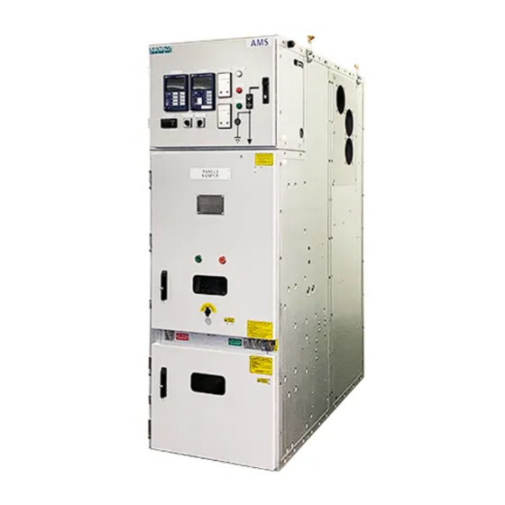
- Page 1 Air-insulated Metal-Clad Switchgear 3.3kV-40.5kV User Manual...
-
Page 2: Table Of Contents
▎ Contents Technical Description ........................... 5 General ..............................5 Applications ............................6 Electrical Characteristics ........................6 Terms and definitions .......................... 9 Operating Conditions ......................... 13 Degrees of protection .........................14 Colour of external surface .........................14 Functional areas and compartments ....................14 Loss of service continuity ........................ 15 1.10 Compartments ............................ - Page 3 ▎ Contents Commissioning ..............................59 Transportation ..............................59 General ............................ …………..59 Dimensions and Weights ..........................60 Loading, Transporting & Positioning Panels .................... 60 Transporting with Rollers ......................………..60 Storage .............................. ………..61 Switchgear Maintenance ........................……..62 General ............................
-
Page 4: Technical Description
1 Technical Description General The “ AMS” series of switchgear is an air insulated, factory -assembled and type tested medium voltage switchgear for indoor installations. The switchgear is an air insulated metal enclosed fully withdrawable switchgear design, fitted with Vacuum Circuit Breakers. -
Page 5: Applications
Services Supermarkets • Shopping malls • Hospitals • Large infrastructures and civil works. • Electrical Characteristics AMS 12 AMS 24 Description Unit Rated service voltage kV rms System highest voltage kV rms Rated frequency Rated current of main bus bar... - Page 6 DQC-40.5 Description Unit AMS12 AMS 24 Ingress Protection • High voltage parts 11.1 IP4X • Open Enclosures 11.2 IP2X 11.3 • Low voltage compartment IP2X Maximum temperature rise at rated º C normal current (CB in unit) Resistance voltage drop across contacts at rated normal current 14.1...
- Page 7 AMS 24 AMS12 Description Unit Minimum time interval between inspections for lubrication and maintenance of moving parts • Mechanism and 24.1 Years drive system Years 24.2 • Interrupters • Isolating contacts – CB 24.3 Years • Isolating contacts – Fixed 24.4...
-
Page 8: Terms And Definitions
Description Unit AMS 12 AMS 24 Rated lightning impulse withstand voltage 42.1 • Conductor toearth 42.2 • Across isolationdistance Maximum number of cables per phase 43.1 • 630A 4 cable sizes 3 cable sizes 43.2 • 1250A 4 cable sizes 3 cable sizes 43.3... - Page 9 1.4.7.1 Interlock-controlled accessible compartment Compartment containing high-voltage parts, intended to be opened for normal operation and/or normal maintenance as stated by the manufacturer, in which access is controlled by integral design of the switchgear and controlgear NOTE Installation, extension, repairing, etc. are not considered as normal maintenance. 1.4.7.2 Procedure-based accessible compartment Compartment containing high-voltage parts, intended to be opened for normal operation and/or normal maintenance as stated by the manufacturer, in which access is controlled by a suitable procedure...
- Page 10 1.4.13 Component Essential part of the main or earthing circuits of metal -enclosed switchgear and controlgear which serves a specific function (for example, circuit -breaker, disconnector, switch, fuse, instrument transformer, bushing, busbar 1.4.14 Main circuit (of an assembly) All the conductive parts of metal -enclosed switchgear and controlgear included in a circuit which is intended to transmit electrical energy.
- Page 11 1.4.25 Removed position (of a removable part) Position of a removable part when it is outside and mechanically and electrically separated from the enclosure 1.4.26 Loss of service continuity category (LSC) Category defining the possibility to keep other compartments and/or functional units energised when opening a main circuit compartment NOTE 1 The LSC category describes the extent to which the switchgear and controlgear are intended to remain operational in case access to a main -circuit compartment is necessary.
-
Page 12: Operating Conditions
"puncture" is used when a disruptive discharge occurs through a solid dielectric. 1.5 Operating Conditions The AMS switchgear has been designed for normal operating conditions for in indoor installations, in compliance with AS 2650:2005 and IEC 62271 -1 Ed 1.0 (2007). -
Page 13: Degrees Of Protection
1.7 Colour of external surface The AMS switchgear is normally supplied with our standard colour finish which is RAL 7035 for the VCB door, cable compartment door, LV compartment door, rear covers and each end panel of the switchboard while the rest of the switchboard is natural galvabond. -
Page 14: Loss Of Service Continuity
According to the updated rules, the AMS switchgear can be defined as follows: 1.9.1 Interlock controlled accessible compartment Compartment containing high-voltage parts, intended to be opened for normal operation and/or normal maintenance, in which access is controlled by integral design of the switchgear and controlgear, such as the circuit breaker compartment and the cable compartment. -
Page 15: Compartments
1.9.3 LSC2B Busbar, Cable and LV compartments are physically and electrically segregated. This is the category that defines the possibility of keeping other compartments and/or functional units energised when opening a main circuit compartment. 1.9.4 Partition Class-PM Metal-enclosed switchgear and controlgear providing continuous metallic partitions and/or shutters, intended to be earthed, between opened accessible compartments and live parts of the main circuit. -
Page 16: Interlocks
• The earth switch cannot be opened unless the cable compartment door is closed. 1.11.2 Key Interlocks The AMS switchgear can also be supplied with the following optional key interlock features to be integrated into equipment isolation and access systems: •... -
Page 17: Arc Proof
When developing modern medium voltage switchgear, personnel safety must necessarily take first place and this is why the AMS switchgear has been designed and tested to withstand an internal arc due to a short-circuit current of the same level as the maximum short -time withstand level. Tests undertaken prove that the metal housing of the AMS switchgear is able to protect personnel operating near the switchgear in the case of a fault which evolves as far as striking an internal arc. -
Page 18: Type Tests
Dimensions of the room, with special attention to the height 1.13 Type Tests The AMS switchgear is designed in accordance with the Australian and IEC Switchgear Standards. The switchgear is fully type tested and compliant with AS 62271.200:2005 and IEC 62271-200, Ed1.0 (2003). -
Page 19: Mechanical Configurations
When developing modern medium voltage switchgear, personnel safety must necessarily take first place and this is why the AMS switchgear has been designed and tested to withstand an internal arc due to a short -circuit current of the same level as the maximum short -time withstand level. The tests show that the metal housing of the switchgear is able to protect personnel working near the switchgear in the case of a fault which evolves as far as striking an internal arc. - Page 20 Front View Side View NOTE The Standard panel h eight is 2250 mm, however if panel identification plate is fitted on top of LV compartment, the height increases to 2300 mm. Typical Switchgear Dimensions (12kV)
- Page 21 Front View Side View NOTE The Standard panel height is 2250 mm, however if panel identification plate is fitted on top of the LV compartment, the height increases to 2300 mm. Typical Switchgear Dimensions (24kV)
- Page 22 1.14.2 Typical switchgear variants Bus-Riser (with Bus-Tie (with Incoming / optional CT’s optional Earth Outgoing and VT’s) switch and VT’s Feeder (with optional CT’s and VT’s) Incoming / Bus Riser Outgoing Bus Riser Bus Riser Bus Tie (with (with bus Feeder (with (with optional (with optional...
- Page 23 1.14.3 Variants of type AMS 12 kV, 630A Switchgear A typical configuration of an incomer/feeder panel with circuit breaker, cable connector, current and voltage transformers. Individual pressure relief vents for internal arc containment Main Busbar LV compartment compartment Metal segregation...
- Page 24 1.14.4 Variants of type 12 kV,1250A Switchgear A typical configuration of a panel with circuit breaker, cable connector, current and voltage transformers and an arc tunnel to vent out hot ionised gases under an internal arc fault. The arc tunnel is utilised when the floor to ceiling height of 4.9m is not available or the design require s venting of hot ionised gases outside the switchroom.
- Page 25 1.14.5 Variants of type AMS 12 kV,1250ASwitchgear A typical configuration of a Bus-Tie panel with circuit breaker, current transformers, earth switch and a coupling section to connect the bus-section to the bus riser panel. Riser busbar through bushings A typical configuration of Bus-Tie panel (12kV)
- Page 26 1.14.6 Variants of type AMS 12 kV,1600A/2000/2500A Switchgear A typical configuration of a Busbar Riser panel. A bus riser panel is required in conjunction with a Bus tie panel (see fig 1.6).The Bus -riser panel can also be fitted with an earth switch, to be used to earth a section of the main busbar.
- Page 27 1.14.7 Variants of type AMS 12 kV, 2000/2500A Switchgear A typical configuration of an Incomer/Feeder circuit breaker panel with cable connector, current and voltage transformers. Typical configuration of an Incomer/Feeder 2000/2500A CB panel (12kV)
- Page 28 1.14.8 Variants of type AMS 24 kV, 630/1250A Switchgear A typical configuration of a feeder panel with circuit breaker, cable connector, current transformer. Current transformer Configuration of a typical Feeder CB panel (24kV)
- Page 29 1.14.9 Variants of type AMS 24 kV, 1250A Switchgear A typical configuration of a Bus-Tie panel with circuit breaker, current transformer and a coupling section to connect the bus-section to the bus riser panel. Bus riser through bushings A typical configuration of Bus -Tie panel (24kV)
- Page 30 1.14.10 Variants of type AMS 24 kV, 1250A Switchgear A typical configuration of a Bus-Riser with bus CT. A bus riser panel is required in conjunction with a Bus tie panel (see fig 1.11). A typical configuration of Bus -Riser with Bustie CT panel (24kV)
- Page 31 1.14.11 Variants of type AMS 24 kV, 1250A Switchgear A typical configuration of a Busbar Riser panel. A bus riser panel is required in conjunction with a Bus tie panel (see fig 1.11).The Bus-riser panel can also be fitted with a earth switch, to be used to earth a section of the main busbar.
- Page 32 1.14.12 Variants of type AMS 24 kV, 1600A/2000A Switchgear A typical configuration of a feeder/incomer panel with circuit breaker, voltage transformer and current transformer. Configuration of a Feeder/Incomer panel with VT and CT (24kV)
-
Page 33: Operation
2 Operation 2.1 General The relative work and operating procedures must be carried out carefully by trained specialists familiar with the installation, taking into account all the relative safety regulations according to the AS, IEC and other relevant professional standard bodies, as well as any Australian and site work regulations and instructions. - Page 34 2.2.2 Internal identification The main internal electrical and mechanical operating components of the CB are Close Coil Close blocking magnet Trip Coil No1 Trip Coil No2 Undervoltage release (space) CB Control card Racking motor CB auxiliary contact block Spring charge motor 2.2.3 CB Compartment door identification The main mechanical components fitted to the CB compartment door are Compartment Door operating handle...
-
Page 35: Withdrawable Voltage Transformers
2.3 Withdrawable Voltage Transformers There are 2 available options with respect to installing Withdrawable Voltage Transformer truck into a panel. A withdrawable VT truck can replace a CB in a panel and derive its supply from the main busbars of the switchboard (BUS VT) or it can be located in the cable compartment of a standard panel and derive its supply from the cable side supply (CABLE VT). -
Page 36: Vacuum Contactor
Draw-out type handcart the VEC vacuum contactors enhance compatibility with other related products and can be directly splice with AMS switchgear. Insertion of a contactor basically follows the same procedure as that to insert and connect a CB as detailed in section 2.5 below. -
Page 37: Circuitbreaker Racking
2.5 CircuitBreaker Racking The following sections detail the procedure to take a circuit breaker, insert it into a panel and then rack it into the service position. Note: this procedure also applies to a Bus VT panel where the CB is replaced with a withdrawable VT arrangement. 2.5.1 Insertion of CB into compartment Ensure that the CB is in the open position and if necessary mechanically trip the CB using the emergency tripping bar. - Page 38 CB Truck RH locking pin CB Truck locked on CB CB Compartment door in position on CB trolley trolley rotated to open LV Plug Interlock CB Compartment door CB Trolley position in mechanism in latched opened front of compartment position CB Trolley locked in CB being inserted into CB inserted and locked in...
- Page 39 2.5.2 LV Plug connection To allow the CB to be racked in, the LV plug must be connected which engages the LV plug interlock mechanism. This mechanism is detailed in section 2.7.1 below and prevents the CB compartment door from closing unless the LV plug is properly connected. LV Plug in foreground with LV Plug engaged with socket socket behind...
- Page 40 2.5.5 Earth Switch Interlock Before racking can occur, the panel earth switch must be open as detailed in section 0 below. This ensures that the mechanical interlock between CB and earth switch is in the correct position to allow CB racking. Earth switch open mechanical indicator visible through cable Earth switch operating mechanism...
-
Page 41: Earth Switch Operation
2.5.8 CB Electrical racking operation (refer to section 2.4.7 for CB manual racking operation) Referring to the electrical control circuits for the panel, initiate the electrical racking in of the CB either by pushbutton activation, PLC/SCADA control or via the ‘Rack In’ pushbutton on the front of the racking controller (where enabled) THE CB IS NOW IN THE SERVICE POSITION. - Page 42 Earth switch handle inserted for Earth switch operating mechanism operation closed indication Earth switch closed mechanical indicator visible through cable Cable compartment door open compartment door viewing window (arrow points to indicator) 2.6.2 Earth switch opening The panel earth switch has a snap action mechanism which acts independently of the rotation of the drive shaft.
-
Page 43: Electrical Interlocks
2.7 Electrical Interlocks Electrical interlocks have been incorporated in to the design to ensure correct and safe operation of the switchgear and prevent unauthorised movements or operation of switchgear. 2.7.1 CB Compartment door limits In conjunction with the CB compartment door interlock detailed in section 2.7.2 below, the CB compartment door has 2 independent limit switches activated by opening the door. - Page 44 2.7.3 Manual Racking access handle limit The manual racking access handle limit is incorporated in the electrical interlock sequence associated with electrical racking of the CB. When the access handle is operated to allow insertion of the manual racking handle, the limit is activated preventing electrical racking.
-
Page 45: Mechanical Interlocks & Locks
2.8 Mechanical Interlocks & Locks Mechanical interlocks have been incorporated in to the design to ensure correct and safe operation of the switchgear and prevent unauthorised movements or operation of switchgear. 2.8.1 LV Plug Interlock The LV plug interlock prevents the CB from being either mechanically or electrically racked into the service position unless the LV plug is correctly fitted. - Page 46 2.8.2 CB Compartment Door Interlock In conjunction with the CB compartment door limits detailed in section 2.6.1 above, the racking mechanism on the CB is fitted with 2 roller actuators that are operated by closing the CB compartment door. If these actuators are not operated (i.e.
- Page 47 2.8.5 CB Lock In conjunction with the CB Lock limit detailed in section 2.6.2 above, the CB Lock prevents the CB from being manually racked into the service position via a mechanical stop that extends behind the CB truck. When the CB Lock is engaged and pulled forward, the mechanical stop extends preventing the CB truck from being racked in.
- Page 48 2.8.6 Earth Switch Lock There are 2 Earth Switch Lock mechanisms; the first one locking the earth switch open and the second locks the earth switch closed. Each lock mechanism is fitted with a slide plate identical to the CB lock which can be locked in position using a standard 6mm padlock or with an optionally fitted key interlock.
-
Page 49: Troubleshooting
2.9 Troubleshooting Some of the common operational issues faced, possible causes and solutions are listed below. Problem Possible Cause Solution Trip circuit breaker Circuit breaker cannot be racked Circuit breaker is closed Open earth switch in from TEST position to Earth switch is closed SERVICE position Racking blocking magnet is... -
Page 50: Installation Of Switchgear
3 Installation of Switchgear 3.1 General Requirements The installation of the switchgear must be carried out carefully by trained specialists familiar with the installation, taking into account all the relative safety regulations according to the AS, IEC and other relevant professional standard bodies, as well as any Australian and site work regulations and instructions. - Page 51 3.3.1 650mm Wide Panel (12kV) Power cable entry *Top Control cable entry * Control cable entry from TOP is through the gland plate of the LV compartment. 3.3.2 800mm wide panel (12kV) Power cable entry *Top Control cable entry * Control cable entry from TOP is through the gland plate of the LV compartment.
- Page 52 3.3.3 1000mm Wide panel (12kV) Power cable entry *Top Control cable entry * Control cable entry from TOP is through the gland plate of the LV compartment. 3.3.4 800mm Wide panel (24kV) Power cable entry *Top Control cable entry * Control cable entry from TOP is through the gland plate of the LV compartment.
-
Page 53: Main Busbar Installation
3.3.5 1000mm Wide Panel (24kV) Power cable entry *Top Control cable entry * Control cable entry from TOP is through the gland plate of the LV compartment. 3.4 Main Busbar Installation The torque settings listed below are to be followed for installation of the main busbar system. Failure to follow these recommendations may result in component failure under situations of extreme stress. - Page 54 3.4.1 Busbar Connection Rear Figure 3.4.1 – Busbar connection Description Panel branch/dropper busbar Through bushing Busbar Chamber Rubber support pad Main busbar Insulation shield Hex bolt M12x45 DIN 912 Hex nut, M12 DIN 934 Contact washer, top & bottom, Size 12 DIN 6796...
- Page 55 3.4.2 Main busbar dimensions for on-site connections When the AMS switchgear arrives on site, the main busbars for connection of each panel, phase to phase, will be supplied in a separate crate. To facilitate ease of connection, the following table shows the different combinations and dimensions of the required busbars.
-
Page 56: Arc Tunnel
3.5 Arc Tunnel For switchroom internal ceilings lower than 4900mm or when additional safety measures are required to expel hot ionised gases from the switchgear, a type tested arc tunnel should be fitted. The tunnel extends the entire length of the switchgear arrangement covering the switching, busbar and cable compartments pressure relief vents in the top of the switchgear. -
Page 57: Hv Power Cable Installation
3.8 Earthing It is recommended that the AMS switchgear have at least two separate connections to the installation main earth bar. The main earth bar runs horizontally through each panel in front of the incoming HV cable gland plate. -
Page 58: Final Assembly Checks
Panel Earth Bar 3.9 Final Assembly Checks After all installation and assembly steps are completed, the following should be verified as a minimum: • Check the system for signs of damage and repair any paint damage if necessary. • Check all of the bolted joints for tightness and torque verification marks on busbar connections. •... -
Page 59: Commissioning
5 Transportation 5.1 General The AMS switchgear is separated into transport units prior to shipping. The transport units consist generally of separate panels each fitted with four (4) transport lugs for tie down and lifting. Prior to shipping, the plug -in modules are set in the service position and “open”, the doors are closed and all mechanical and electrical connectors between the transport units are removed and supplied as loose parts. -
Page 60: Dimensions And Weights
The top of the panels contain pressure relief vents. Cares should be taken to avoid walking on the top of the panels. Dimensions and Weights The table below lists typical panel dimensions and weights for design purposes. Depending upon the required packing medium used, transport dimensions and weights can vary significantly and may add as much as 200mm to each dimension listed below and approximately 120kg to overall weight. -
Page 61: Storage
6 Storage The AMS panels are delivered as fully assembled units ready to be installed into their final operating positions. If the panels have to be stored for a period of not more than three months, the following minimum conditions are required to prevent any deterioration in quality to the panel s and accessories: •... -
Page 62: Switchgear Maintenance
Only skilled technicians familiar with medium voltage switchgear should perform inspections. The AMS switchgear must be serviced every year as a minimum. This interval is determined by the prescribed maintenance intervals from the various equipment manufacturers, the circuit breakers and findings following previous inspections. -
Page 63: Maintenance Of The Switchgear
Are there visible signs of general soiling in the switchgear room? Any dirt in the switchgear room can detrimentally affect the system’s operation and must be removed immediately. If, during the inspection, you discover any other potentially negative changes to the system beyond those described above, you must eliminate these by implementing appropriate measures. - Page 64 It should be easy to move the doors downwards into the locking position. Mechanical modifications to the oblong slots in the chassis should not be made as this may affect the performance of the switchgear under fault conditions. If the doors do not close properly, the only way to adjust them is by loosening the fastening screws on the inside, realigning the doors and tightening the screws again.
- Page 65 7.3.6 Checking the earthing switch With the earth switch closed, all 3 switch blades should engage their respective fixed contacts firmly and evenly. Check the earthing switch using a mirror. If it has visibly changed, remove the cables and inspect the switch in detail. An earth switch position camera is available as an option.
- Page 66 Distributed by...
Need help?
Do you have a question about the AMS and is the answer not in the manual?
Questions and answers