
Related Manuals for ASRock Industrial 4X4 BOX-7735U/D5


Summary of Contents for ASRock Industrial 4X4 BOX-7735U/D5
- Page 1 4X4 BOX-5000 Series 4X4 BOX-7735U/D5 4X4 BOX-7535U/D5 User Manual Version 1.0 Published May 2022 User Manual...
- Page 2 ASRock Industrial has been advised of the possibility of such damages arising from any defect or error in the documentation or product.
- Page 3 DISPOSE OF USED BATTERIES ACCORDING TO THE INSTRUCTIONS Contact Information If you need to contact ASRock Industrial or want to know more about ASRock Industrial, you’re welcome to visit ASRock Industrial’s website at https://www. asrockind.com; or you may contact your dealer for further information.
-
Page 4: Table Of Contents
Contents Chapter 1 Introduction Package Contents Product Specifications Block Diagram Chapter 2 Product Overview Front View Rear View Inside View Chapter 3 Hardware Installation How to Remove the Bottom Case How to Install the WiFi Module How to Remove the M.2 SSD and the Bracket How to Install the M.2 SSD How to Install the 2.5-inch Hard Drive How to Install the Memory Modules (DDR5) - Page 5 5.1.1 Entering BIOS Setup 5.1.2 UEFI Menu Bar 5.1.3 Navigation Keys Main Screen Advanced Screen 5.3.1 CPU Configuration 5.3.2 Chipset Configuration 5.3.3 Storage Configuration 5.3.4 Super IO Configuration 5.3.5 ACPI Configuration 5.3.6 USB Configuration 5.3.7 Trusted Computing Hardware Health Event Monitoring Screen Security Screen Boot Screen Exit Screen...
-
Page 8: Chapter 1 Introduction
4X4 BOX-7000U/D5 Series Chapter 1 Introduction Because the hardware specifications might be updated, the content of this documentation will be subject to change without notice. 1.1 Package Contents • 4X4 BOX-7000U/D5 Series • 1 x SATA 1 to 1 Cable •... -
Page 9: Product Specifications
1.2 Product Specifications 4X4 BOX-7000U/ Barebone D5 Series 4X4 BOX-7735U/D5 (AMD Ryzen™ 7 7735U, 8Cores, Max Speed up to 4.75GHz) 4X4 BOX-7535U/D5 (AMD Ryzen™ 5 7535U, 6Cores, Max Speed up to 4.55GHz) BIOS AMI SPI 256 Mbit Chipset Memory Supports Dual Channel DDR5 4800 MHz, 2 x 262-pin SO- DIMM slots, Max. - Page 10 4X4 BOX-7000U/D5 Series Front I/O 1 x USB 3.2 Gen2 (Type A), 2 x USB4 (Type C, Supports DP1.4a display output), 1 x Audio- out with MIC-In Rear I/O 2 x USB 2.0 (Type A), 1 x HDMI 2.1, 2 x DP1.4a, 2 x LAN( 1 x 1 Gigabit LAN, 1 x 2.5 Gigabit LAN), DC-IN, 1 x Kensington lock Power Unit...
-
Page 11: Block Diagram
1.3 Block Diagram 4X4-7735U-1U 4X4-7535U-1U HDMI2.1 Channel A DDR5 4800M HZ HDMI RTD2175-CG SO-DIMM DP1.4a Connector Channel B DDR5 4800M HZ SO-DIMM RTS5452E Type-C USB4 USBC0 Connector KB8002 PCIe x4(#16~#19) M.2 Key M USB2.0(P2) RTS5452E Type-C USB4 USBC1 Connector KB8002 SATA PCIe x1(#8) PCIE to SATA Hub... -
Page 12: Chapter 2 Product Overview
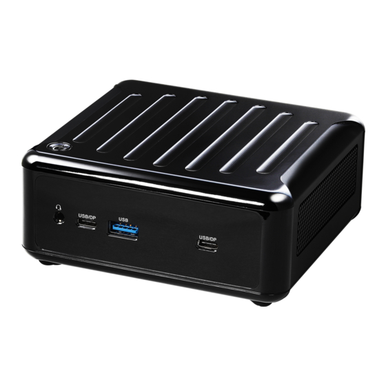
4X4 BOX-7000U/D5 Series Chapter 2 Product Overview This chapter provides diagrams showing the location of important components of the 4X4 BOX-7000U/D5 Series. 2.1 Front View Description Audio(Mic-in, Line-out) 2 x USB 4 Ports (Type C, supports DP1.4a display output) USB 3.2 Gen2 (Type A) -
Page 13: Rear View
2.2 Rear View Description DC-IN HDMI RJ-45 (1G)* 2 x USB 3.2 Gen2 Ports DisplayPort RJ-45 (2.5G)** * There are two LEDs on the LAN port. Please refer to the table below for the LAN port LED indications. ACT/LINK LED SPEED LED LAN Port Activity / Link LED... - Page 14 4X4 BOX-7000U/D5 Series ** There are two LEDs on the LAN port. Please refer to the table below for the LAN port LED indications. ACT/LINK LED SPEED LED LAN Port Activity / Link LED Speed LED Status Description Status Description No Link 10Mbps connection Blinking...
-
Page 15: Inside View
2.3 Inside View Description SO-DIMM Slot SATA 3.0 Connector M.2 Slot (Key M, 2242/2260/2280) M.2 Slot (M.2 Key E, 2230 PCIe x1, USB 2.0 for Wireless) Hard disk drive tray (compatible with 2.5" SATA HDD/SSD) SO-DIMM memory, hard drive and mSATA SSD are not included with this system. -
Page 16: Chapter 3 Hardware Installation
4X4 BOX-7000U/D5 Series Chapter 3 Hardware Installation This chapter helps you install or remove important components. 3.1 How to Remove the Bottom Case 1. Remove the four screws on the bottom case. 2. Then lift up and remove the bottom panel.. -
Page 17: How To Install The Wifi Module
3.2 How to Install the WiFi Module 1. Locate the WiFi Module slot on the motherboard. 2. Carefully insert the WiFi Module into the slot. 3. Tighten the screw to secure the WiFi Module to the motherboard. -
Page 18: How To Remove The M.2 Ssd And The Bracket
4X4 BOX-7000U/D5 Series 3.3 How to Remove the M.2 SSD and the Bracket 1. Release the screw and carefully remove the M.2 SSD (Type 2280). 2. Release the screw and remove the bracket from the motherboard. -
Page 19: How To Install The M.2 Ssd
3.4 How to Install the M.2 SSD 1. Locate the M.2 slot on the motherboard. Install the standoff. 2. Carefully insert the M.2 SSD (Type 2260) into the slot. 3. Tighten the screw to secure the M.2 SSD to the motherboard. -
Page 20: How To Install The 2.5-Inch Hard Drive
4X4 BOX-7000U/D5 Series 3.5 How to Install the 2.5-inch Hard Drive 1. Remove the four screws on the bottom case. Then lift up and remove the bottom panel. 2. Attach the HDD to the hard drive mounting bracket and secure it using the four screws. - Page 21 3. Attach the HDD assembly to the bottom panel and secure it using the four screws. 4. Connect the SATA Cable to the connector.
- Page 22 4X4 BOX-7000U/D5 Series 5. Then reinstall the bottom panel.
-
Page 23: How To Install The Memory Modules (Ddr5)
3.6 How to Install the Memory Modules (DDR5) 1. The 4X4 BOX-7000U/D5 Series requires DDR5 SO-DIMM. 2. For dual channel configuration, you always need to install identical (the same brand, speed, size and chip-type) DDR5 SO-DIMM pairs. The SO-DIMM only fits in one correct orientation. It will cause permanent damage to the motherboard and the DIMM if you force the DIMM into the slot at incorrect orientation. -
Page 24: How To Install The Vesa Bracket
4X4 BOX-7000U/D5 Series 3.7 How to Install the VESA Bracket 1. Attach the two screws to the base of the 4X4 BOX-7000/D5 Series. 2. Attach the VESA Bracket to the rear of a compatible display using the four screws. *Choose mounting holes depending on the mounting hole pattern of your LCD screen (75 mm ×... -
Page 25: Chapter 4 Motherboard
Chapter 4 Motherboard 4.1 Motherboard Layout AUDIO1 USB 4.0: TC_U4_1 USB 3.2 Gen2 T: USB3_4 BIOS B: USB3_5 USB2H_2_3 COM1 SATA3_1 USB 2.0: Industrial T: USB2_6 B: USB2_7 USB 4.0: TC_U4_2 DDR5_B1 (Support DDR5 Only) DC_IN1 DDR5_A1 (Support DDR5 Only) 1 : M.2 Key-M Socket (M2M_1) 2 : M.2 Key-E Socket (M2E_1) 3 : USB 2.0 Connector (USB2H_2_3) - Page 26 4X4 BOX-7000U/D5 Series FAN1 PWR_BTN1 BAT1 ESPI1 Back Side : 8 : Power Button (PWR_BTN1) 9 : Fan Connector (FAN1) 10 : Battery Connector (BAT1) 11 : ESPI Connector (ESPI1)
-
Page 27: Motherboard Specifications
4.2 Motherboard Specifications Form Factor Dimensions 4X4 (4.09-in x 4.02-in x 1.4-in, 10.4 cm x 10.2 cm x 3.6 cm) AMD Ryzen™ 7 7735U (Max Speed up to 4.75GHz) Processor AMD Ryzen™ 7 7535U (Max Speed up to 4.55GHz) System Chipset BIOS AMI SPI 256 Mbit... - Page 28 4X4 BOX-7000U/D5 Series Input PWR 12V~19V DC-In Jack AT/ATX Supported Power - AT : Directly PWR on as power input ready Requirements Power On - ATX : Press button to PWR on after power input ready Operating 0ºC ~ 60ºC Temp Storage Temp -40ºC ~ 85°C...
-
Page 29: Onboard Headers And Connectors
4.3 Onboard Headers and Connectors The illustration shows how jumpers are setup. When the jumper cap is placed on pins, the jumper is “Short.” If no jumper cap is placed on pins, the jumper is “Open. ” The illustration shows a 3-pin jumper whose pin1 and pin2 are “Short”... - Page 30 4X4 BOX-7000U/D5 Series SATA3 Port Signal Name (20-pin SATA3_1) (see p. 18, No. 5) R_SATA_RXP0 R_SATA_RXN0 R_SATA_TXN0 R_SATA_TXP0 The Serial ATA3 (SATA3) connector supports SATA data cables for internal storage devices. The current SATA3 interface allows up to 6.0 Gb/s data transfer rate. JP1_12 : SIO AT Mode (8-pin JP1) JP1_34 : CMOS Normal (Default)
- Page 31 PLED (System Power LED): Connect to the power status indicator on the chassis front panel. The LED is on when the system is operating. The LED keeps blinking when the sys-tem is in S1 sleep state. The LED is off when the system is in S3/S4 sleep state or powered off (S5). HDLED (Hard Drive Activity LED): Connect to the hard drive activity LED on the chassis front panel.
-
Page 32: Expansion Slots (M.2 Slots)
4X4 BOX-7000U/D5 Series 4.4 Expansion Slots (M.2 Slots) There are 2 M.2 slots on this motherboard. M.2 for SSD: 1 x M.2 (KEY M, 2242/2260/2280) with PCIe Gen4 x 4 * M.2 Key M 2280(Supported by bracket) M.2 for Wi-Fi: 1 x M.2 (Key E, 2230) with PCIe x1, USB 2.0 for Wireless. M.2 Key-M Socket (M2M_1) M.2 Key-E Socket (M2E_1) Signal Name... -
Page 33: Chapter 5 Uefi Setup Utility
Chapter 5 UEFI Setup Utility 5.1 Introduction ASRock Industrial UEFI (Unified Extensible Firmware Interface) is a BIOS utility which offers tweak-friendly options in an advanced viewing interface. The UEFI system works with a USB mouse and offers users a faster, sleeker experience. -
Page 34: Uefi Menu Bar
4X4 BOX-7000U/D5 Series 5.1.2 UEFI Menu Bar The top of the screen has a menu bar with the following selections: Main For setting system time/date information For advanced system configurations Advanced H/W Monitor Displays current hardware status Security For security settings Boot For configuring boot settings and boot priority Exit the current screen or the UEFI Setup Utility... -
Page 35: Navigation Keys
5.1.3 Navigation Keys Use < > key or < > key to choose among the selections on the menu bar, and use < > key or < > key to move the cursor up or down to select items, then press <Enter>... -
Page 36: Main Screen
4X4 BOX-7000U/D5 Series 5.2 Main Screen When you enter the UEFI SETUP UTILITY, the Main screen will appear and display the system overview. Because the UEFI software is constantly being updated, the following UEFI setup screens and descriptions are for reference purpose only, and they may not exactly match what you see on your screen. -
Page 37: Advanced Screen
5.3 Advanced Screen In this section, you may set the configurations for the following items: CPU Configu- ration, Chipset Configuration, Storage Configuration, Super IO Configuration, ACPI Configuration, USB Configuration, and Trusted Computing. Setting wrong values in this section may cause the system to malfunction. DASH Support Enable or disable Realtek Lan DASH Function. -
Page 38: Cpu Configuration
4X4 BOX-7000U/D5 Series 5.3.1 CPU Configuration PSS Support Enable/disable the generation of ACPI _PPC, _PSS, and _PCT objects. Core Performance Boost Core Performance Boost controls whether the processor transitions to a higher fre- quency than the processor’s rated speed if the processor has available power and is within temperature specifications. -
Page 39: Chipset Configuration
5.3.2 Chipset Configuration IOMMU Enable/Disable IOMMU Support. Share Memory Configure the size of memory that is allocated to the integrated graphics processor when the system boots up. Re-Size BAR Support If the system has Resizable BAR capable PCIe Devices, this option enables or dis- ables Resizable BAR Support. -
Page 40: Storage Configuration
4X4 BOX-7000U/D5 Series 5.3.3 Storage Configuration Third Party SATA Controller(s) The option allows you to enable or disable the SATA controllers. Configuration options: [Enabled] [Disabled] Third Party SATA Mode Selection AHCI supports new features that improve performance. Configuration option: [AHCI] Hard Disk S.M.A.R.T. -
Page 41: Super Io Configuration
5.3.4 Super IO Configuration COM1 Configuration Use this to set parameters of COM1. Type Select Use this to select COM1 port type: [RS232], [RS422] or [RS485]. WDT Timeout Reset Use this to set the Watch Dog Timer. -
Page 42: Acpi Configuration
4X4 BOX-7000U/D5 Series 5.3.5 ACPI Configuration Suspend to RAM Use this item to select whether to auto-detect or disable the Suspend-to-RAM feature. Select [Auto] will enable this feature if the OS supports it. Configuration options: [Auto] [Disabled] Onboard LAN Power On Use this item to enable or disable onboard LAN to turn on the system from the power-soft-off mode. -
Page 43: Usb Configuration
5.3.6 USB Configuration USB Power Control Use this option to control USB power. The default value is [Default Setting]. -
Page 44: Trusted Computing
4X4 BOX-7000U/D5 Series 5.3.7 Trusted Computing NOTE: Options vary depending on the version of your connected TPM module. Security Device Support Security Device Support allows you to enable or disable BIOS support for security device. O.S. will not show Security Device. TCG EFI protocol and INT1A interface will not be available. - Page 45 Platform Hierarchy This item allows you to enable or disable Platform Hierarchy. Configuration options: [Enabled] [Disabled] Storage Hierarchy This item allows you to enable or disable Storage Hierarchy. Configuration options: [Enabled] [Disabled] Endorsement Hierarchy This item allows you to enable or disable Endorsement Hierarchy. Configuration options: [Enabled] [Disabled] Physical Presence Spec Version Select this item to tell OS to support PPI spec version 1.2 or 1.3.
-
Page 46: Hardware Health Event Monitoring Screen
4X4 BOX-7000U/D5 Series 5.4 Hardware Health Event Monitoring Screen In this section, it allows you to monitor the status of the hardware on your system, including the parameters of the CPU temperature, motherboard temperature, CPU fan speed, chassis fan speed, and the critical voltage. NOTE: Options vary depending on the features of your motherboard. -
Page 47: Security Screen
5.5 Security Screen In this section, you may set, change or clear the supervisor/user password for the system. Supervisor Password Set or change the password for the administrator account. Only the administrator has the authority to change the settings in the UEFI Setup Utility. Leave it blank and press enter to remove the password. -
Page 48: Boot Screen
4X4 BOX-7000U/D5 Series 5.6 Boot Screen In this section, it will display the available devices on your system for you to config- ure the boot settings and the boot priority. Boot Option #1 The item allows you to set the system boot order. Boot From Onboard LAN The item allows the system to be waked up by the onboard LAN. -
Page 49: Exit Screen
5.7 Exit Screen Save Changes and Exit When you select this option, the following message “Save configuration changes and exit setup?” will pop out. Select [Yes] to save the changes and exit the UEFI SETUP UTILITY. Discard Changes and Exit When you select this option, the following message “Discard changes and exit setup?”... -
Page 50: Chapter 6 Software Support
4X4 BOX-7000U/D5 Series Chapter 6 Software Support 6.1 Install Operating System ® ® This motherboard supports various Microsoft Windows operating systems: 10 64-bit. Because motherboard settings and hardware options vary, use the setup procedures in this chapter for general reference only. Refer your OS documentation for more information.
Need help?
Do you have a question about the 4X4 BOX-7735U/D5 and is the answer not in the manual?
Questions and answers