Advertisement
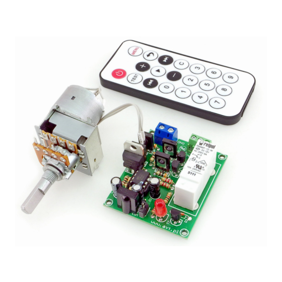
Remote-Controlled Potentiometer
kits
For Audio Applications
The device is perfectly suited to any audio amplifier
equipped with a standard 'manual' potentiometer.
This circuit can be controlled by virtually any infrared
remote control, requiring only a simple remote code
memorisation procedure. It was tested with several
pilots from different televisions, decoders, DVDs and
audio equipment - with each it worked properly.
Any button on the remote control can be assigned to
one specific function: turn left (volume down), turn
right (volume up) or on/off. This makes it possible to
use remote control buttons normally not used.
The controller is a versatile circuit. After the exchange
of the potentiometer for a geared motor, it can
control, for example, window blinds.
Circuit description
Electrical diagram of the circuit is shown in Figure 1.
The controller is built on an 8-lead microcontroller
ATtiny45, which is equipped, among other things,
with a non-volatile EEPROM where codes will be
stored for individual commands that control the
circuit operation. Components R2, C2 are
responsible for resetting the processor during power
on. The microcontroller does not require any
external quartz resonator as it has an integrated RC
generator. The TFMS5360 infrared receiver is
connected to the PB4 input of the processor. Light
emitting diode D1 is used to signal the status of
relay PK1 controlled by transistor T7 from output
Characteristics
• remote control by any infrared remote control
• simple teaching mode for remote controller
• ability to assign any remote control keys for three
functions:
- turn anticlockwise
- turn clockwise
- control of integrated relay (e.g., ON/OFF)
• power supply: 12 VDC
• remote control and potentiometer with motor
included
PB2 of the processor, it also has a useful function
when teaching codes sent by the remote control.
This circuit must be supplied with a DC voltage of
approx. 14 VDC. The digital part of the device is
powered by +5 VDC, supplied by the US2 voltage
stabiliser. Each received command coming from the
transmitter is analysed by the processor. If it
corresponds to one of the predefined commands,
the motor is set in motion for the time specified by
the transmission time and in set direction. Each
received command assigned to relay PK1 changes its
state to the opposite. The relay type RM96 is
designed for switching currents of up to 8 A, which
PDF
DOWNLOAD
ASSEMBLY DIFFICULTY
1
Advertisement
Table of Contents

Summary of Contents for AVT 594
- Page 1 Remote-Controlled Potentiometer kits For Audio Applications DOWNLOAD ASSEMBLY DIFFICULTY The device is perfectly suited to any audio amplifier Characteristics equipped with a standard 'manual' potentiometer. • remote control by any infrared remote control This circuit can be controlled by virtually any infrared •...
- Page 2 in most cases is enough to activate amplifier polarise transistor T5, as well as transistors T4 and circuits. Diode D2 protects transistor T7 from the T1. Current will flow through the path: +power effects of surges occurring on the relay coil at the supply, transistor T1, motor winding , transistor T4 time of switching off.
- Page 3 most cases, you want that only one button had this confirmation by the circuit) corresponding key on function, so it had to be pressed twice. Such action your remote control. After this action, the relay will is needed for correct operation with some remote switch on briefly, which is an incentive to enter the controls.
- Page 4 AVT SPV reserves the right to make changes without prior notice.Installation and connection of the appliance not in accordance with the instructions, unauthorised modification of components and any structural alterations may cause damage to the appliance and endanger persons using it. In such a case, the manufacturer and its authorised representatives shall not be liable for any damage arising directly or indirectly from the use or malfunction of the product.
Need help?
Do you have a question about the 594 and is the answer not in the manual?
Questions and answers