
Summary of Contents for Axis Industries SDU-1M
- Page 1 AB “AXIS INDUSTRIES” ULTRASONIC FLOW SENSOR SDU – 1M TECHNICAL DESCRIPTION, OPERATING INSTRUCTION...
-
Page 2: Table Of Contents
TABLE OF CONTENTS 1. Application ................ 2. Technical data..……............3. Package content..…............. 4. Operating principle............... 5. Sealing ……………………..........6. Safety …………….............. 7. Installation ……..............8. Calibration ………………………………………………. 9. Transportation and storage ..........10. Warranty ................Appendixes: Appendix A. Dimensions of flow sensor and connection flanges Appendix Connection terminals of flow sensor PESDU1M02 (MID) -
Page 3: Application
As a component of heat energy meter the SDU-1M flow sensor could by used for commercial account of energy quantity in district heating plants, in factories, in single or multi family houses. - Page 4 2.5.Table of default settings of the pulse value depending on the permanent flow rate and sensor size: Permanent flow q , m3/h Pulse value, liter/ pulse 0,02 0,02 0,05 0,05 Other pulse value settings could be selected according user needs by ordering the flow sensor. The pulse value is also indicated on the label of the flow sensor.
-
Page 5: Package Content
Remark: 1. LED indication begins when the button is pushed down. Status signals E (Error) and D (Direction) are passive signals and should be wired using the open drain output signal connection diagram such shown in 2.6.1 p. 2.8. When the measured flow rate exceeds maximal flow q per +10 %, the flow sensor transmits the amount of pulses which corresponds to the flow rate q +10 % and indicates corresponding... -
Page 6: Sealing
5. SEALING The following flow sensor sealing is provided: 5.1. Manufacturer seals: Adhesive seal-sticker on the bolts of cover protecting ultrasonic transducers (Appendix A, Figures A1,A2 and A3). Hanged seal on ultrasonic transducers mounted in flow sensor (Appendix A, Figures A4). 5.2. -
Page 7: Calibration
Fig.1. Positioning of flow sensors: a) – not recommended position; b) and c) – recommended positions for flow sensors with threaded end connection G1 1/4 (q = 3,5 m /h and 6,0 m /h), G2 (q = 10,0 m /h) and flanged connection DN50 (q = 15,0 m /h);... -
Page 8: Transportation And Storage
2 of this document, if transportation, storage and operation conditions will be followed. Warranty period - 12 months from bringing into operation, but not more than 18 months from manufacturing date. Manufacturer’s address: AB “AXIS INDUSTRIES”, Kulautuvos g. 45a, LT47190 Kaunas, Lithuania Phone: (+370 37) 360234;... - Page 9 Appendix A. Sizes and dimensions Connection Thread G1 1/4 Thread G1 1/4 Fig. A1. Dimensions of flow sensors with q = 3,5 m /h; 6,0 m Connection 10,0 Fig. A2. Dimensions of flow sensor with q = 10,0 m Connection 15,0 DN50 Fig.
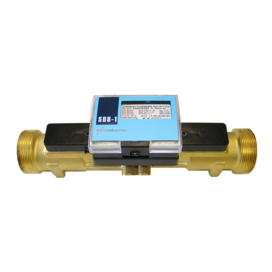
- Page 10 Appendix B1 Connection terminals of flow sensor SDU-1M Lithium battery Calibration seal Button for status 3,6V, 8Ah, size C indication Battery connection terminal BAT LED for status indication (green and red) Pulse, status and external powering signal connection terminals: Pulse output signal configuration U+ –...
- Page 11 Appendix B2 Connection of pulse cable Supply of flow sensor SDU-1 from external (calculator) battery The internal battery is not installed, if SDU-1 is powered from the external power supply Configuration of pulse output: Red (+U) - Jumper should be set on pins 1-2 (active output) when calculator and flow sensor is powered from ...
- Page 12 Appendix B3 Set up of “Test” mode and configuration of output pulse signals for calibration Test mode is set on by placing the jumper on the 13-14 pins in contactors J1 Configuration of output pulse transmission mode: Jumper on 1-2: Active mode Jumper on 2-3: Passive mode (open drain electrical connection) PESDU1M02 (MID)
Need help?
Do you have a question about the SDU-1M and is the answer not in the manual?
Questions and answers