Table of Contents
Advertisement
Quick Links
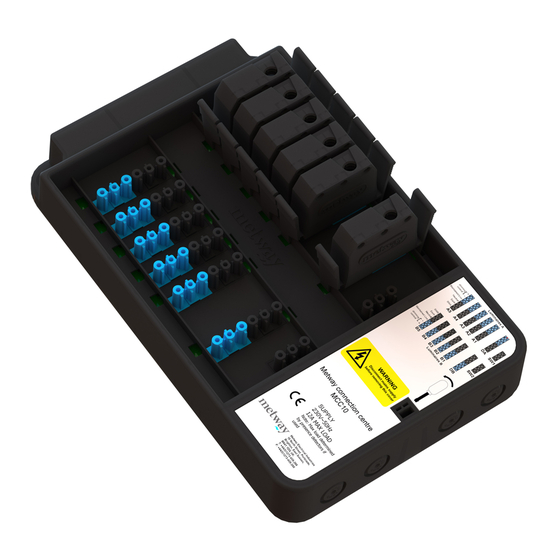
MCC connection centre
MCC10B (G)
MCC8B (G)
Installation Instructions.
WARNING 230V a.c.
The connections of this equipment should be made by a suitably
qualified person in accordance with the current wiring
regulations.
It is strongly recommended to use Metway latching connectors.
Use G suffix for black/grey connectors and B suffix for black/blue
connectors when ordering.
The Metway MCC connection centre provides a simple way to
integrate presence detectors and luminaires using industry standard
connectors. Up to 2 detectors can be connected to up to 10 luminaires
dependant on the control philosophy required.
Electrical Connections
Screw terminations are provided in the wiring aperture underneath the
cover for power supply connections and external dimming applications.
Override switches may also be connected here in order to provide
switched live connections to the luminaires or presence detector
override connections.
Appropriate means of supply disconnection and overcurrent protection
should be provided by the installation. Please refer to wiring diagrams
overleaf for further information.
The cover of the wiring aperture is removed by inserting the blade of a
flat screwdriver into the catch and applying light pressure on the
handle towards the output connectors on the MCC while lifting the
outside edge of the cover.
The cable entries for 20mm conduit, bushes or glands are semi-
pierced in the end wall of the wiring aperture and can be knocked out
carefully using a flat bladed screw driver and small hammer.
Alternatively these can be removed with a 20mm hole saw.
A cable gland must be used to provide a strain relief if the cabling is
not routed into the MCC via conduit or trunking.
Fixing
The MCC should be sited on a flat, smooth surface using the 2no fixing
flanges located at the end of the MCC and the 2no fixing holes located
in the wiring aperture.
It is not advised that the MCC is fixed using rod suspensions although
this can be done as long as the fixing is substantial enough to
withstand the action of plugging and unplugging the connectors without
damage to the MCC housing and also ensuring latching is engaged.
Factory configuration
When the unit is supplied from the factory, the dimming control and
switch lives are linked in the terminations in the wiring aperture. LK2
and LK3 MUST BE REMOVED if 2 detectors with dimming outputs are
connected to the MCC.
Connections are made to the terminal strip connector as highlighted in
figure 2. There are 2no live input terminals for looping of live feeds to a
switch position. This allows for direct wiring of the supply cable to the
MCC. Please refer overleaf for connection diagrams.
Live (L/IN) is routed to the 2no detector inputs (D1 and D2)
Maintained Live (ML) is routed to the 10 (if MCC10) or 8 (if MCC8)
luminaire outputs. If no separate maintained live is required a link will
need to be fitted between M/L and L/In terminal.
SWA is the switched live output from a detector connected to D1.
SWB is the switched live output from a detector connected to D2.
LK1 is the link connection between the switched live from each
detector input. It must be removed to split the luminaires into 2 groups.
The dimming control signal from each detector to its group of
luminaires is via the PIR inputs (D1 or D2). Alternatively connections
can be made via the dimming channel screw terminations in the wiring
aperture. (A+ A- or B+ B-) links are factory fitted to allow for single
channel dimming (all outputs off 1 dimming detector/ input). If 2no
dimming detectors are to be connected to the MCC LK2 and LK3 need
to be removed.
Figure 2
Technical data
OPERATING VOTAGE: 230V 50Hz (UK & Europe)
PRODUCT RATING: 12 Amps *
RECOMMENDED CIRCUIT PROTECTION: 10 Amps
MAXIMUM LOAD PER OUTPUT: 6 Amps *
MAXIMUM TOTAL LOAD: 12 Amps *
SUPPLY TERMINAL CAPACITY: 4.00mm
DIMMING TERMINAL CAPACITY: 4.00mm
CASE MATERIAL: POLYCARBONATE V0
CASE FINISH: LIGHTLY SPARKED, BLACK.
* Note: These specifications refer to the MCC being used as
simple wiring device without presence detectors. When using
mains switching presence detectors it is the presence detector
that dictates the maximum load. It is imperative that the total load
connected to an MCC does not exceed that of the presence
detector connected. Please check the specification of the
connected detector and do not exceed its maximum load
(typically 6 Amps)
CE
Metway Electrical Industries
Barrie House
18 North Street
Portslade
Brighton
East Sussex
BN41 1DG
Tel: +44 (0) 1273 439 266
Fax: +44 (0) 1273 439 288
Email:
sales@metway.co.uk
www.metway.co.uk
2
2
(2 X 1.50mm
)
2
2
(2 X 1.50mm
)
Advertisement
Table of Contents

Subscribe to Our Youtube Channel
Summary of Contents for Metway MCC10B
- Page 1 Use G suffix for black/grey connectors and B suffix for black/blue connectors when ordering. The Metway MCC connection centre provides a simple way to integrate presence detectors and luminaires using industry standard connectors. Up to 2 detectors can be connected to up to 10 luminaires dependant on the control philosophy required.
- Page 2 It is important to note that in this scenario the feed to the dimmable ballast would be also switched via the relay in the Metway presence detector. 2 dimming detectors with 8 or 10 luminaires and absence switches (momentary push to make)
- Page 3 PIR c/w 3m lead with absence DSI/DALI ballasts important to note that in this scenario the feed to the dimmable MCCMW603P mid range microwave detector c/w 3m lead ballast would be also switched via the relay in the Metway (switching only) presence detector. MCCMW603PAB mid range microwave detector c/w 3m lead with 2 hardwired switches for dual channel switching.
Need help?
Do you have a question about the MCC10B and is the answer not in the manual?
Questions and answers