Advertisement
Advertisement
Table of Contents

Related Manuals for Vitilan i7 Pro

Summary of Contents for Vitilan i7 Pro
- Page 1 ...
-
Page 2: Table Of Contents
Importance………………………………………………………………………… P1 Models and Pictures……………………………………………………………… P2 Specifications ………………………………………………………………………... P3 Safety and Compliance with the Law ……………………………… P4 Assembling Your New e-Bike……………………………………………………… P5-P10 Operating Your New e-Bike ……………………………………………………… P11-P13 Middle Set Negative LCD Display(UKS2)…………………………………… P14-P29 Care and Maintenance……………………………………………………………… P30 Safety …………………………………………………………………………………. -
Page 3: Importance
11. Do not use the bike for other than intended use. 12. Save these instructions. *Note that this is a general manual. VITILAN reserves the right to make changes to products and designs. The e-bike you own may not be the same style as the pictures shown in this manual. - Page 4 2 ...
-
Page 5: Specifications
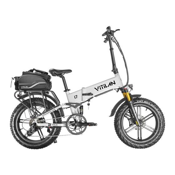
Specifications ● MODEL: i7 Pro ● Frame Construction: Aluminum alloy folding full suspension frame ● Wheelbase: 1150mm ● Gear Range: SHIMANO 8-speed type ● Tire Size: 20" (565mm) ● Climb Grade: 30 degree ● Max load: 150kg (330 lb) ●... -
Page 6: Safety And Compliance With The Law
Read This First: Safety and Compliance with the Law Congratulations on your purchasing of your new e-bike. Your new e-bike is an excellent piece of personal transportation equipment that will give you good service for many years. Before you start using your e-bike, we want you to be aware of a few important points. Please read this section carefully. -
Page 7: Assembling Your New E-Bike
Assembling Your New e-Bike If you purchased your e-bike unassembled, please follow these instructions to assemble your e-bike under the guidance of an adult or a qualified technician. Assembly is quite easy as most of the parts are already assembled; you need only to put a few pieces together to complete the job. - Page 8 6 ...
- Page 9 Air Shock Absorption Front Fork 7 ...
- Page 10 Check that the Package is Complete and Undamaged Your e-bike comes in a carton containing the following: The main body of the e-bike – consisting of the frame, the front and rear wheel, the gear and chain, the front and rear brake, the battery on the frame, the rear fender....
- Page 11 Assembly - Step 1: Attach the handlebar subassembly Stand the main body of the e-bike on the kickstand. Stand up and lock the steering column that is at the front of the main body frame, insert the stem of the handlebar subassembly into it.
- Page 12 Note: Under normal circumstances, the rotation directions of the left and right pedals are different. 1. When installing the left pedal, turn the installation tool counterclockwise. 2. When installing the right pedal, turn the installation tool clockwise. Liability statement: Due to the model and time of manufacture of pedals may vary.
-
Page 13: Operating Your New E-Bike
Operating Your New e-Bike The method to turn on the bike is: I. Turn on the battery; II. Press power button on the left handle bar until the display lights on; III. Ride on the bike and twist the throttle bar or pedal the bike, the bike will move, you can change the power level with control buttons, level 1 is the slowest and level 5 is the fastest, level 0 is human model. - Page 14 Cruise Control Cruise Control will be triggered when you holding thumb throttle for 8 seconds, and it will be released by braking/pedaling or throttling. Thumb throttle Control In the hand throttle mode, amount of power assist is determined by the throttle switch controlled by your left hand.
- Page 15 connected to the battery for a very long period of time after charging is complete. (Leaving it connected for an overnight charging is OK.) It is normal for the charger and the battery to be slightly hot while charging is on- going.
-
Page 16: Middle Set Negative Lcd Display(Uks2)
Middle Set Negative LCD Display(UKS2) 1. Production Name Middle set negative LCD display 2. Model UKS2 3. SPEC 24V/36V/48V/60V/72V/UBE power supply Rated power 1W USB charge DC 5V 500mA Power off leak currant<1uA ... - Page 17 5. Production Introduction Speed display: including real-time speed “RT SPEED”, “MAX SPEED”, average speed “AVG SPEED” SEETING SPEED SCALE(mph/kph): Km / mile display can be set according to customer habits Intelligent battery indicator: Provide stable battery reminder through optimization algorithm, power is not affected by motor start-stop fluctuations, if the system supports battery communication, it can display accurate percentage power ...
- Page 18 6. LCD Display Instructions LCD Full Display As Follow: Brake Indicator Faulty Indicator Front Light Power Indicator USB Indicator Speed Mode Value Indicator Speed Mode Speed Circle Mileage Mode Gear Indicator Value Indicator Speed mode: Average speed (AVG SPEED), maximum speed (MAX SPEED), real-time speed (RT SPEED) ...
- Page 19 7. Function Description Plus Button Power Button Mode Button Minus Button Button description as follow: Power On/Off Power Button Long press(1 second) when the display is off, display, the display is fully displayed Power Button and starts to work, the power of the controller is turned on; Long press(1 second) when the display is on, display power off, the power of the controller is turned off.
- Page 20 Power Button When power on, short-press to switch the mileage display mode, and the following information is displayed cyclically: riding time (Time) → accumulated mileage (ODO) → power information (Pow) → single mileage (Trip). *If there is no key operation for 5 seconds, the meter will automatically return to...
- Page 21 Average Speed(AVG) Max Speed(MAX) Real time speed(SPEED) *If there is no key operation for 5 seconds, the meter will automatically return to the real-time speed display state. 7.5 Headlight / Backlight Switch Plus Button Press and hold (1 second), the brightness of the meter's backlight decreases, and the lights Plus Button ...
- Page 22 Walking Mode Off Walking Mode On 7.7 USB Function Long press (1 second), the USB function is turned on, the user can use the USB function, and long press for more than 1 second, the display will close the USB function, and the charging parameter is DC 5V 500mA.
- Page 23 8. MENU Parameter Setting When power on, press twice (<0.3 seconds between presses), the system enters the parameter setting state. In this state, the meter parameters can be set. Press twice again to exit the setting state. (<0.3 seconds between presses). When in setting state, press to select the desired adjustment item, when the parameter flashes, press...
- Page 24 Automatic shutdown time: for item P2, press to adjust the position, 1 ~ 9 minutes represents the automatic shutdown time, OFF means cancel the automatic shutdown function. Automatic Shutdown time Adjust Interface Universal/ England: for item P3, press to switch km/h or MPH display, set Universal/ England: 0 stands for universal system and 1 stands for England system.
- Page 25 Password input: Enter ADS advanced setting items, the speed position of the display shows “ADS”, indicating that entering the password can enter advanced setting items. Short press to enter the password input state, the speed position of the display will show “PSD” at the same time, prompt for the password, press to set the password value (0 ~ 9), press to switch the password item, the password is 4 digits, and the default password "1801", press...
- Page 26 Voltage Choices Interface Assistance gear selection: item A2, to set the gear range 3/5/9/6. 1 means 3-speed system; 2 means 5-speed system; 3 means 6-speed system; 4 means 9-speed system. Assistance gear selection Interface ...
- Page 27 Speed Limiting Adjustment Interface Currant Limiting Adjustment: item A4, Press to adjust the current limit value. The default is 15A. Users can set the current limit value according to their needs. After the adjustment is completed, press to confirm and exit. Currant Limiting Adjusting Interface *Speed and current are restricted by the motor and controller at the same time and may not be able to reach the set value.
- Page 28 Number of speed measuring magnets: item A6, press to adjust the number of speed measuring magnets 1 ~ 72. The user can set the number of speed measuring magnets according to the requirements. After the adjustment is completed, press confirm and exit.
- Page 29 PAS orientation: item A9, press to select the direction of the power sensor. PAS orientation Adjustment Interface 9. Error Code Definition UKS1 can provide error indications for vehicle faults. When a fault is detected, the LCD screen displays , and the error code “n”...
- Page 30 10. Installation Instruction 10.1 Please refer to the following figure for the instrument screw assembly. Pay attention to the screw tightening torque. Instrument damage caused by excessive torque is not covered by the warranty. M3*8mm M4*12mm Display host and ...
- Page 31 11. Cable Outlet Definition The color of the five-core waterproof line is <red, blue, black, green, and yellow>. The order is defined as follows: 1、 RED:Power+ (Battery power 24V/36V/48V) 2、 Blue:Controller lock cable 3、 Black:GND 4、 Green:RXD display input signal, display receives signal from controller 5、...
-
Page 32: Care And Maintenance
Care and Maintenance for Your New e-Bike You should, in general, take care of your e-bike the way you would with a regular bicycle by keeping it dry, clean and the moving parts well lubricated. You should also avoid parking your e-bike in exposed areas whenever possible. -
Page 33: Safety
Safety These safety precautions are provided for your benefit to protect you and those around you. Please read and follow them carefully to avoid unnecessary injury, damage to the product, or damage to other property. ● Battery ● Battery Charger ... - Page 34 32 ...
-
Page 35: Trouble Shooting
Trouble Shooting As one or more causes of failure might lead to the failure phenomenon, you should find out the true cause(s) and then take the appropriate solution(s) to rectify the problem. In case of doubt, please consult a qualified technician for service, repairs or maintenance.
Need help?
Do you have a question about the i7 Pro and is the answer not in the manual?
Questions and answers