Table of Contents
Advertisement
Quick Links
Installation and Operating Manual for Components
®
HST
-M2
HST-M2 Ident.-No.: 10788
HST-M2 Ident.-No.: 10823
HST-M2 Ident.-No.: 11051
HST-M2 Ident.-No.: 11215
HST-M2 Ident.-No.: 12090
HST-M2 Ident.-No.: 12120
HST-M2 Ident.-No.: 12188
HST-M2 Ident.-No.: 12242
HST-M3 Ident.-No.: 10555
HST-M3 Ident.-No.: 10649
HST-M3 Ident.-No.: 11029
HST-M3 Ident.-No.: 12077
HST-M3 Ident.-No.: 12288
HST-M4 Ident.-No.: 10844
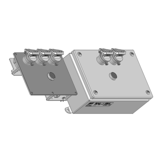
Figure shows HST-M3 Ident.-No.: 10649 and HST-M2 Ident.-No.: 10342
Read the operating manual before beginning any work!
HST
/
Switching element with locking mechanism
(
Translation of Original Manual
The image may differ from the product.
Haake Technik GmbH
Master Esch 72
48691 Vreden, Deutschland
info@haake-technik.com
www.haake-technik.com
Tel.: +49 2564 39650
Fax: +49 2564 396590
®
-M3
/
)
HST-M2 Ident.-No.: 10342
HST-M2 Ident.-No.: 10343
HST-M2 Ident.-No.: 10358
HST-M2 Ident.-No.: 10503
HST-M2 Ident.-No.: 10504
HST-M2 Ident.-No.: 10584
HST-M2 Ident.-No.: 12261
HST-M2 Ident.-No.: 12307
HST-M3 Ident.-No.: 10334
HST-M3 Ident.-No.: 10335
HST-M3 Ident.-No.: 10818
HST-M3 Ident.-No.: 10985
HST-M3 Ident.-No.: 11196
HST-M4 Ident.-No.: 10505
HST-M4 Ident.-No.: 10554
HST-M4 Ident.-No.: 10560
HST-M4 Ident.-No.: 12170
HST-M4 Ident.-No.: 12277
®
HST
-M4
Advertisement
Table of Contents

Summary of Contents for Haake HST-M2
- Page 1 HST-M4 Ident.-No.: 10554 HST-M4 Ident.-No.: 10560 HST-M4 Ident.-No.: 12170 HST-M4 Ident.-No.: 12277 Figure shows HST-M3 Ident.-No.: 10649 and HST-M2 Ident.-No.: 10342 The image may differ from the product. Read the operating manual before beginning any work! Haake Technik GmbH Master Esch 72 48691 Vreden, Deutschland info@haake-technik.com...
-
Page 2: Table Of Contents
No parts of this documentation may be reproduced or transferred in any manner or by any means, be it electronic or mechanical, for any purpose without obtaining prior written consent. Haake Technik GmbH assumes no liability for damage or subsequent damage, arising from the use of components or replacement parts, which are not original parts. -
Page 3: Scope
If you have any questions which are not answered in this manual, please get in touch with your re- gional customer service centre or else make direct contact with Haake Technik GmbH Master Esch 72, 48691 Vreden, Germany Telephone +49 2564 39650 Fax +49 2564 396590 Info@haake-technik.com... -
Page 4: Foreseeable Misuse
Foreseeable misuse Never operate the keys with extended lever arms. This can damage the internal components and may render the safety function inoperative. Do not attempt to unlock the component with objects other than the corresponding keys. Do not attempt to insert or remove a key by applying excessive force or with the aid of a tool (hammer). -
Page 5: Defects Which Cannot Occur
Defects which cannot occur Due to the construction, materials, and components used for the component, the faults listed in the table can be excluded: Potential Defect Elimination of Defect Limitations of Use Reason Wear, corrosion. Permissible acc. See sections 2 Application of carefully Intended use and tables A.4 and A.5 of... -
Page 6: Scope Of Delivery
Scope of delivery Built-in version: 1 x switching element with locking mechanism HST-M incl. drilling template Housing version: 1 x switching element with locking mechanism HST-M incl. set for wall mounting 1 x technical information for the inbuilt switch properly coded keys acc. to number of locks NOTE! Means of attachment are not included in the scope of the delivery. -
Page 7: Example
10.2 Example Position 1 Switch key and key change blocked by locking mechanism. Keys cannot be removed. Switch key change key Position 0 Switch key unblocked and can be removed. Figure shows HST-M3 Ident.-No.: 10649... -
Page 8: Safety Measures
Do not make any alterations to the component. Otherwise, this could lead to malfunctions, which can cause serious personal injury and irreparable damage to property. In the event of non-compliance, the guarantee is invalidated and Haake Technik GmbH does not ac- cept any liability. -
Page 9: Installation
Installing the component requires the following items that are not included in the scope of the delivery: HST-M2: built-in version (Ident.-No.: 10788, 10823, 11051, 11215, 12090, 12120, 12188, 12242; 12307) 4 screws + M5 nuts from A2-70 ... -
Page 10: Installation Instructions
Make the mounting holes according to the design of the component. The mounting holes should be arranged as shown in the diagrams (cf. section 20: Dimensions) and the drilling template. Built-in version: To support the delivery of a drilling template assembly is attached. Figure shows HST-M2 Ident.-No.: 10649 Assembly group Lock M3 screw... - Page 11 Carry out the electrical connection (cf. section 12.4). Place the housing lid [B] back on the housing box [C] with the HST-M2 and screw it in place with the 4 lid screws [A]. Make sure the protective earthing conductors are not squashed or disconnected.
-
Page 12: Electrical Connection
The electrical connection of the switching element with locking mechanism HST-M is shown in the following circuit diagram for: HST-M2 Ident.-No.: 10343, 10504, 12120, 12242, 12261 HST-M3 Ident.-No.: 10555, 10335, 10818, 10985, 11029, 11196 HST-M4 Ident.-No.: 10505, 10560, 10844, 12170, 12277 Position 1: Switch key S1 locked by locking mechanism. - Page 13 HST-M2 Ident.-No.: 10342, 10584 HST-M3 Ident.-No.: 10334, 10649 HST-M4 Ident.-No.: 10554 Position 1: Switch key S1 locked by locking mechanism. Switch S2 is not pressed. Switch position ON Position 0: Switch key is unlocked and removed from S1. S2 button pressed. Switch position OFF...
- Page 14 HST-M2 Ident.-No.: 10358 Position 1: Switch key S1 locked by locking mechanism. Switch S2 is not pressed. Switch position ON Position 0: Switch key is unlocked and removed from S1. S2 button pressed. Switch position OFF terminal block X1 terminal block X2...
- Page 15 HST-M2 Ident.-No.: 10503, 11051; 12307 HST-M3 Ident.-No.: 12077 Position 1: Switch key S1 locked by locking mechanism. Switch S2 is not pressed. Switch position ON Position 0: Switch key is unlocked and removed from S1. S2 button pressed. Switch position OFF...
- Page 16 HST-M2 Ident.-No.: 10788 Position 1: Switch key S1 locked by locking mechanism. Switch S2 is not pressed. Switch position ON Position 0: Switch key is unlocked and removed from S1. S2 button pressed. Switch position OFF terminal block X1 terminal block X2...
- Page 17 HST-M2 Ident.-No.: 10823 Position 1: Switch key S1 locked by locking mechanism. Switch S2 is not pressed. Switch position ON Position 0: Switch key is unlocked and removed from S1. S2 button pressed. Switch position OFF terminal block X1 terminal block X2...
- Page 18 HST-M1 Ident.-No.: 11215 Position 1: Switch key S1 locked by locking mechanism. Switch S2 is not pressed. Switch position ON Position 0: Switch key is unlocked and removed from S1. S2 button pressed. Switch position OFF terminal block X1 terminal block X2 terminal block X3 terminal block X4 ==============...
- Page 19 HST-M1 Ident.-No.: 12090 Position 1: Switch key S1 locked by locking mechanism. Switch S2 is not pressed. Switch position ON Position 0: Switch key is unlocked and removed from S1. S2 button pressed. Switch position OFF terminal block X1 terminal block X2 terminal block X3 ============== ==============...
- Page 20 HST-M2 Ident.-No.: 12188 HST-M3 Ident.-No.: 12288 Position 1: Switch key S1 locked by locking mechanism. Switch S2 is not pressed. Switch position ON Position 0: Switch key is unlocked and removed from S1. S2 button pressed. Switch position OFF terminal block X1...
-
Page 21: Performance Check
13 Performance check Attention! The protective effectiveness of the compo- nent must be checked regularly - at least once a year - in intervals according to national operat- ing instructions Once installed, do not loosen any bolts or nuts or remove any pins; otherwise, the effectiveness of the safety-related func- tions is no longer guaranteed. -
Page 22: Operation
14 Operation Attention! Never operate the key with extended lever arms. This may destroy the inner compo- nents and disable the safety function. Do not attempt to unlock the component with objects other than the corresponding keys. Do not ever attempt to insert or remove a key by applying excessive force or with the aid of a tool (hammer). -
Page 23: Cleaning
16 Cleaning No cleaning is required, as a rule. Attention! In dusty environments (e.g. cement dust, colour dust), only clean the component with compressed air. Only use other cleaning methods after prior consultation with the manufacturer. 17 De-installation Attention! Only uninstall the component when power to the electrical system is switched off. -
Page 24: Troubleshooting
Wrong key / wrong coding. Check labelling on the key and turned. on the component. Deformed key. Check key. Contact Haake Technik in case of defor- mation. Key inserted incorrectly. Remove the key and if neces- sary insert it rotated 180°. -
Page 25: Technical Data
19 Technical data Environment: indoor / outdoor Temperature range: Built-in version: -25 °C to +40 °C Housing version: -25 °C to +40 °C Humidity: to 100% (standard climate) Material: Lock: stainless steel Built-in version, Ident.-No.: 10555, 10649, 10788, 10823, 10844, 11029, 11051, 11215, 12077, 12090, 12120, 12188 12242, 12288;... -
Page 26: Dimensions
HST-M2 Ident.-No.: 11215 HST-M2 Ident.-No.: 12090 HST-M2 Ident.-No.: 12120 HST-M2 Ident.-No.: 12188 HST-M2 ident.-No.: 12242 HST-M2 ident.-No.: 12307 Figure shows HST-M2 Ident.-No.: 10788 HST-M3 Ident.-No.: 10555 HST-M3 Ident.-No.: 10649 HST-M3 Ident.-No.: 11029 HST-M3 Ident.-No.: 12077 HST-M3 Ident.-No.: 12288 Figure shows HST-M3 Ident.-No.: 10649... - Page 27 HST-M4 Ident.-No.: 10844 Housing version: HST-M2 Ident.-No.: 10342 HST-M2 Ident.-No.: 10343 HST-M2 Ident.-No.: 10358 HST-M2 Ident.-No.: 10503 HST-M2 Ident.-No.: 10504 HST-M2 Ident.-No.: 10584 HST-M2 Ident.-No.: 12261 Figure shows HST-M2 Ident.-No.: 10342...
- Page 28 HST-M3 Ident.-No.: 10334 HST-M3 Ident.-No.: 10335 HST-M3 Ident.-No.: 10818 HST-M3 Ident.-No.: 10985 HST-M3 Ident.-No.: 11196 Figure shows HST-M3 Ident.-No.: 10334 HST-M4 Ident.-No.: 10505 HST-M4 Ident.-No.: 10554 HST-M4 Ident.-No.: 10560 HST-M4 Ident.-No.: 12170 HST-M4 Ident.-No.: 12277 Figure shows HST-M4 Ident.-No.: 10505...
-
Page 29: Ec Declaration Of Conformity
21 EC Declaration of Conformity... - Page 32 Haake Technik GmbH Master Esch 72 48691 Vreden, Deutschland info@haake-technik.com www.haake-technik.com Tel.: +49 2564 39650 Fax: +49 2564 396590...
Need help?
Do you have a question about the HST-M2 and is the answer not in the manual?
Questions and answers