
Subscribe to Our Youtube Channel
Related Manuals for New Focus LB1005


Summary of Contents for New Focus LB1005
- Page 1 Operating Manual LB1005 High-Speed Servo Controller Bookham 2584 Junction Ave. San Jose, CA 95134 (408) 919-1500 Item No. P2102297 Rev. A...
-
Page 3: Table Of Contents
LB1005 Operating Manual Table of Contents Contents Contents........................ i Chapter 1 : Introduction..................1 Safety Considerations ........................1 Table of Symbols ..........................1 Parts List ............................2 Electrical Fuse & Voltage Selection ....................2 Front Panel Connections & Controls.....................3 Rear Panel Connections & Controls .....................5 Chapter 2 : Getting Started................ -
Page 5: Chapter 1: Introduction
LB1005. Safety Considerations The LB1005 is a versatile instrument that can be used in a variety of feedback control applications. However, the LB1005 is not intended for fail-safe operation in hazardous environments or life-threatening situations. The user... -
Page 6: Parts List
• AC Power Cord Electrical Fuse & Voltage Selection The LB1005 is pre-configured at the factory to work with the AC mains voltages for your region. Before supplying electrical power to the LB1005, confirm that the power entry module located on the rear panel is installed with the proper fuses and set to the correct wallplug AC voltage. -
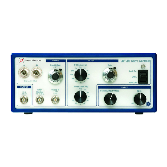
Page 7: Front Panel Connections & Controls
± 10 V and a bandwidth of 10 MHz. 4. Sweep In: This BNC input allows a low frequency periodic sweep signal to be added to the output of the LB1005. The input impedance is 1 M Ω and the Bookham Revision 1... - Page 8 Introduction LB1005 Operating Manual input voltage range is ± 10 V. See Sweep Center and Sweep Span controls discussed below for more details. 5. Output: This BNC output is the control signal from the proportional-integral (P-I) filter, summed with the sweep and modulation signals. This output has an impedance of 50 Ω...
-
Page 9: Rear Panel Connections & Controls
LB1005 Operating Manual Introduction 12. LED lock indicator: This LED light indicates the operating status of the LB1005. Table 3 shows the correspondence of the LED color to the operating conditions of the LB1005. Table 3: LED Lock Indicator LED Color... - Page 10 Introduction LB1005 Operating Manual 3. Input Offset Range: This 3-position switch determines the voltage range for the Input Offset front panel knob. For more information, please see the above section Front Panel Connections & Controls). Selecting the Off position disables the Input Offset control so that no voltage offset is added.
-
Page 11: Chapter 2: Getting Started
Demanding applications will require familiarity with feedback control theory and good characterization of all system components. The primary function of the LB1005 is to condition an input signal from a detector and to provide an output signal to a transducer that controls a system parameter. - Page 12 LB1005 Output will usually feed a high-voltage amplifier that connects to the PZT. Be careful not to exceed any input voltage limits of the transducer. If necessary, the Output voltage of the LB1005 can be limited by Revision 1...
- Page 13 Error Monitor output on an oscilloscope is highly recommended. 4. Function generator output to LB1005 Sweep In: For detector signals that are derived from optical resonances, it is convenient to sweep the transducer so that the optical frequency scans over the resonance. Observing the resonance...
-
Page 14: Typical Operation
Note that the two lock points have opposite gain signs. Typical Operation The controls of the LB1005 are conveniently arranged for acquiring and optimizing lock. In this section, five steps are suggested that will meet the needs of most applications. - Page 15 LB1005 Operating Manual Getting Started Figure 5: Typical Operation of Controls The Lock On position disables the low-frequency gain limit and applies the full integrator gain to the output. Most servo systems should be locked in this position to minimize DC errors. When correctly locked, the Error Monitor signal should be very near zero volts, and the LED indicator light should be green (see Figure 6 for more details.)
- Page 16 Getting Started LB1005 Operating Manual Error Monitor Output Signal Maximum Input Voltage (+10 V) Maximum Output Voltage (+10 V) Positive Voltage Limit V - 0.1 ∆V Full Voltage Range Positive Saturation Voltage (0.33 V) ∆V Ground (0 V) Ground (0 V) Negative Saturation Voltage (-0.33 V)
-
Page 17: Chapter 3 : Detailed Operation
Chapter 3 : Detailed Operation Signal Architecture The LB1005 is comprised of three stages of analog signal processing. Figure 7 shows the different sections and how the various input signals are used to derive the output signal. Each section is briefly described below. See Appendix A for more detailed specifications. -
Page 18: Filter Transfer Functions
Detailed Operation LB1005 Operating Manual Filter Transfer Functions This section describes the transfer functions available from the P-I filter, which are shown in Figure 8. The filter is specifically designed to have independent control over the three main parameters that shape the filter frequency response: •... -
Page 19: Setting Output Voltage Limits
Setting Output Voltage Limits The positive and negative voltage limits of the LB1005 Output can be independently adjusted with the Output Voltage Limit trimpots located on the rear panel. The following procedure can be used to set the output voltage limits: 1. -
Page 20: Using The Integrator Hold
LB1005 Operating Manual Using the Integrator Hold The LB1005 has a feature that allows the user to electronically trigger the integrator output to “hold” its current value. When a TTL digital “high” signal is applied to the rear panel Int Hold BNC connector, the error signal input to the filter stage integrator is disabled until the TTL signal goes to a “low”... -
Page 21: Appendix A: Specifications
LB1005 Operating Manual Specifications Appendix A: Specifications A.1. Performance specifications Parameter Unit Condition Signal bandwidth (-3 dB) Propagation delay <10 MHz − V Input Section: Difference amplifier −B Error Offset Ω Input impedance (A, -B) Input voltage (A, -B) −B... - Page 22 Specifications LB1005 Operating Manual A.2. Environmental Specifications Parameter Unit Condition ° C Operating temperature ° C Transportation/storage temperature Maximum relative humidity Maximum operating altitude 2000 Instrument weight A.3. Electrical Specifications Parameter Classification Use type Indoor Use Only Protection Ordinary Protection (Not protected against ingress of moisture)
-
Page 23: Appendix B: Service & Maintenance
Appendix B: Service & Maintenance The LB1005 is designed to be maintenance free. No user-serviceable parts are inside the unit. No further calibrations are necessary for the LB1005 to meet its accuracy specifications over the lifetime of the product. Opening the instrument case voids the warranty and exposes to user to hazardous voltages that are present inside the instrument case. -
Page 25: Appendix C: Warranty
The LB1005 should not be used in a manner not specified by the manufacturer.
Need help?
Do you have a question about the LB1005 and is the answer not in the manual?
Questions and answers