Table of Contents
Advertisement
Available languages
Available languages
Quick Links
Advertisement
Table of Contents

Summary of Contents for PMK ATT10BNCS
- Page 1 DE | EN Probing Solutions. Made in Germany. ATT10BNCS Breitbandiges Dämpfungsglied für LILCO terminierte Stromwandler Wide-Band Attenuator For Use With LILCO Terminated Current Transformers Bedienungsanleitung | Instruction Manual...
-
Page 2: Garantie
Garantie PMK gewährt eine Garantie für die Dauer von 2 Jahren nach Versand für dieses Stromwandler-Zubehör für normalen Ge- brauch und Betrieb innerhalb der Spezifikationen. Jedes defekte Produkt wird repariert oder ersetzt, wenn es nicht durch Nachlässigkeit, Fehlanwendung, unsachgemäße Installation, Unfall, nicht autorisierte Reparatur oder Änderung durch den Kunden beschädigt wurde. - Page 3 ATT10BNCS Über den ATT10BNCS Das Dämpfungsglied ATT10BNCS wird verwendet, um die untere Grenzfrequenz zu reduzie- ren, das I-t (Produkt aus Strom und Zeit) zu erhöhen sowie den Droop (Dachschräge) und den Ausgangsfaktor von PMK LILCO-Stromwandlern zu reduzieren. Die Dämpfung des Ausgangs eines terminierten LILCO Stromwandlers wird durch Verringe- rung des Ausgangswiderstands des Stromwandlers erreicht.
- Page 4 ATT10BNCS IEC Messkategorien Definitionen und Beispiele: Messzubehör ohne Definition: Viele Arten von Prüf- und Messstromkreisen sind nicht für den direkten Anschluss an das Versorgungsnetz bestimmt. Einige dieser Bemessungsdaten Messstromkreise sind nur für Niedrigenergieanwendungen geeignet, für eine Messkate- andere dieser Messstromkreise können aber mit sehr großen Mengen verfügbarer Energie durch hohe Kurzschlussströme oder hohe Leer-...
- Page 5 ATT10BNCS IEC Verschmutzungsgrade Definitionen: Übersicht der Messkategorien nach IEC 61010-031 O = Messzubehör ohne Bemessungsdaten für eine Messkategorie (Andere Stromkreise, die nicht direkt mit dem Netz verbunden sind) Verschmutzungsgrad 1 Es tritt keine oder nur trockene, nicht leitfähige VERSCHMUTZUNG auf.
-
Page 6: Spezifikationen
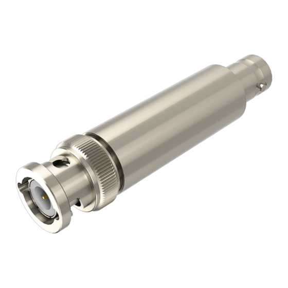
ATT10BNCS Spezifikationen ATT10BNCS Elektrische Spezifikationen Dämpfungsverhältnis 20 dB Dämpfungstoleranz ± 0,25 dB Frequenzbereich DC - 50 MHz Ausgangsimpedanz 50 Ω ± 1 % Eingangsleistung, RMS 2,25 W Maximale bemessene Peak Eingangsspannung, Messzubehör ohne Bemessungsdaten für eine Messkategorie, nicht in CAT II, III, IV (¹) Verschmutzungsgrad Messzubehör ohne Bemessungsdaten für... - Page 7 Die HF-Eigenschaften bleiben erhalten. Bedienungsanleitung - Verbinden Sie das Dämpfungsglied mit der Seite des ATT10BNCS, die mit "Stromwandler" gekennzeichnet ist, mit einem LILCO Stromwandler. - Schließen Sie Ihr Messgerät an der Seite an, die auf dem Etikett mit "Oszilloskop" gekenn- zeichnet ist.
-
Page 8: Warranty
PMK will not be liable for any indirect, special, incidental, or consequential damages (including damages for loss of profits, loss of business, loss of use or data, interruption of business and the like), even if PMK has been advised of the possibility of such damages arising from any defect or error in this manual or product. -
Page 9: Safety Information
The attenuation of the output of a terminated LILCO current transformer is achieved by redu- cing it's output resistance of the current transformer. The LILCO current transformer's internal shunt resistor is normally 50 Ω. By applying ATT10BNCS to the output of the transformer it's output in V/A is reduced by the factor of 10. - Page 10 ATT10BNCS IEC Measurement Categories Definitions and Examples No Measurement Definition: Many types of test and measuring circuits are not intended not in CAT II, III or IV to be directly connected to the mains supply. Some of Category these measuring circuits are intended for very low energy applicati-...
- Page 11 ATT10BNCS IEC Pollution Degrees Definitions and Examples: Overview of measurement categories according to IEC 61010-031 O = No Measurement Category (Other circuits that are not directly connected to mains) Pollution Degree 1 No POLLUTION or only dry, non conductive POLLUTION.
-
Page 12: Environmental Specifications
ATT10BNCS Specifications ATT10BNCS Electrical Specifications Attenuation ratio 20 dB Attenuation tolerance ± 0.25 dB Frequency range DC - 50 MHz Output impedance 50 Ω ± 1 % Input power, RMS 2.25 W Maximum Rated Input Peak Voltage, No Measurement Category, not in CAT II, III, IV (¹) -
Page 13: Description Of Functions
50 MHz. For measurements of pulses up to 25 kA or small currents in the mA range in LF or RF power electronic circuits the PMK current transformers of the LILCO series are ideal- ly suited. Only use insulated cables for the conducting wire, which is placed into the LILCO current transformer. - Page 14 ATT10BNCS Notes...
- Page 15 ATT10BNCS Notes...
- Page 16 Copyright © 2020 PMK - All rights reserved. Informationen in dieser Anleitung ersetzen die in allen bisher veröffentlichten Dokumenten. Änderungen der Spezifikationen vorbehalten. Information in this publication supersedes that in all previously published material. Specifications are subject to change without notice.
Need help?
Do you have a question about the ATT10BNCS and is the answer not in the manual?
Questions and answers