
Related Manuals for Lovol TE Series


Summary of Contents for Lovol TE Series
- Page 1 LOVOL TE Series Wheeled Tractor ARBOS TE Series Wheeled Tractor TE4043C, TE4043R, ARBOS 2040 Operation Manual Weichai Lovol Heavy Industry Co., Ltd. of the People's Republic of China...
- Page 2 Purchase place and contact information User name Name of manufacturer Weichai Lovol Heavy Industry Co., Ltd. of the People's Republic of China Address of manufacturer No. 192, South Beihai Road, Fangzi District, Weifang City, Shandong Province, the People's Republic of China...
- Page 3 Instructions to Users Dear users, Thank you for your trust in our company, and buy LOVOL TE and ARBOS TE series wheeled tractors produced by our company. Please pay attention to the following important information in order to use the tractor correctly, reasonably and efficiently: 1.
- Page 4 This Instruction Manual introduces in detail the safety precautions, running-in, use, technical maintenance, adjustment, faults and troubleshooting methods of LOVOL TE and ARBOS TE series wheeled tractors, which can be used as a reference for tractor drivers and maintenance personnel.
- Page 5 Overview hazardous substances, such as those where pesticides are sprayed, or under conditions that may lead to falling or puncture. Please provide supporting agricultural implements (see agricultural implements listed in Appendix 9.5) correctly in accordance with the requirements of this manual to obtain the maximum economic benefits. The user shall strictly observe the use, maintenance and repair conditions specified by the manufacturer and the basic requirements for expected application.
- Page 6 Comparison between Chinese and English Units Comparison between Chinese and English Units Unit type International unit Time Length Force Torque N· m Weight Pressure kgf/cm ℃ Temperature Speed km/h Angular velocity r/min Current Voltage Volume Flow rate L/min Power Oil consumption: g/kW·...
- Page 7 Chinese and English Comparison of Common Units Chinese and English Comparison of Common Units Unit category International unit Chinese version Second Time Minute Hour Millimeter Centimeter Length Meter Newton Force Torque N· m N· m Kilogram Mass Gram Kilopascal Pressure Megapascal kgf/cm Kgf/cm...
-
Page 9: Table Of Contents
Table of Contents Table of Contents 1Safety Precautions --------------------------------------------------------------------------------------------------------1 1.1 Safety Rules and Precautions for Use---------------------------------------------------------------------------1 1.2 Safety Warning Signs----------------------------------------------------------------------------------------------8 2 Product Mark -------------------------------------------------------------------------------------------------------13 3 Operating Instructions ------------------------------------------------------------------------------------------15 3.1 Product Description----------------------------------------------------------------------------------------------16 3.2 Tractor Control Mechanism and Instrument-------------------------------------------------------------------16 3.3Starting of Engine-------------------------------------------------------------------------------------------------24 3.4 Starting of Tractor-------------------------------------------------------------------------------- -----------------27 3.5 Steering of Tractor---------------------------------------------------------------------------- --------------------27 3.6 Shift of Tractor--------------------------------------------------------------------------- -------------------------28... - Page 10 ---------------------------------------------------------------91 7.1 Delivery and Acceptance-----------------------------------------------------------------------------------------91 7.2 Transportation-----------------------------------------------------------------------------------------------------91 8 Technical Specifications ---------------------------------------------------------------------------------------93 8.1 Product Model---------------------------------------------------------------------------------------------------93 8.2 Main Technical Specifications of TE Series Tractors------------------------------------------------------93 9 Dismantling and Disposal -------------------------------------------------------------------------------------98 10 Warranty Items -------------------------------------------------------------------------------------------------99 10.1 Basis of Product Warranty-------------------------------------------------------------------------------------99 10.2 Cases of Non-warranty----------------------------------------------------------------------------------------99...
-
Page 11: 1Safety Precautions
Safety Precautions 1 Safety Precautions 1.1 Safety Rules and Precautions for Use Must-read before operation 1. The driver must fully read and understand the vehicle usage and maintenance specifications and safety warning signs introduced in the Instruction Manual. 2. The driver must remember the correct operation and operation methods. Fig. - Page 12 Safety Precautions Fig. Use of Fuel 1. The fuel is flammable, and it is strictly prohibited to approach the fire during filling. 2. The engine must be shut down before refueling the fuel tank. 3. Do not smoke when refueling and overhauling the fuel system. 4.
- Page 13 Safety Precautions Proper support of tractor 1. If the tractor or its components must be lifted, they shall be safely supported so as to lower the components or appliances on the ground. 2. Do not support the machine with coal cinders, (hollow) bricks, hollow tiles or other supports that may fracture under sustained pressure.
- Page 14 Safety Precautions Precautions for installing farm implements or tractor-trailer 1. Before trailed implements or trailers are installed, the engine must stop running and the tractor shall be parked in a safe position. Please read the installation instructions of farm implements or trailers, symbolic meanings and user manuals carefully.
- Page 15 Safety Precautions unilateral brake to avoid the risk of rollover. 11. When the tractor is running on the road, it is necessary to pay attention to traffic signs and strictly abide by traffic regulations to avoid accidental safety hazards. 12. During the transfer, the traffic rules must be strictly observed, and the driving distance between two tractors shall be at least 60m, so as to avoid accident danger of collision.
- Page 16 Safety Precautions 30. Tractors are strictly prohibited to operate in thunderstorm weather. Vehicle and personal injury may be caused easily otherwise. 31. When removing the installation machinery, lower the machine to the ground first. Notes: 1. The bolts, nuts and easy-to-loosen parts at various connecting parts, such as fixing nuts of front and rear drive wheels and connecting nuts of steering rod, shall be checked frequently, and tightened in time in case of any looseness, so as to avoid accidental danger.
- Page 17 Safety Precautions the universal joint drive shaft shall be not more than 15° . When the hydraulic control is normal, the included angle between the power take-off shaft and the input shaft of farm implements and the drive shaft shall be not more than 20°...
-
Page 18: Safety Warning Signs
Safety Precautions When the tractor is abnormal 1. Do not allow the tractor to work "with fault", In particular, when there is no oil pressure, too low oil pressure and too high water temperature or abnormal noise and smell, it is necessary to stop the tractor in time for inspection and troubleshooting. - Page 19 Safety Precautions Meaning: When the lifting rod control mechanism is working, keep away from the lifting area of the pull rod to avoid personal injury; Sticking position: rear end of the left and right sides of mudguard. Fig. 1-15 Safety Warning Sign III Meaning: Before repair, maintenance and adjustment, it is necessary to shut down the engine, pull out the start key and operate in accordance with the requirements of the Operation Manual to avoid personal injury;...
- Page 20 Safety Precautions Meaning: Only after all parts of the machine have stopped working completely, can they be contacted to avoid personal injury; Sticking position: on the protective cover of PTO (power take-off shaft). Fig. 1-20 Safety Sign for Power Output Meaning: During maintenance of the battery, please refer to the Operation Manual for correct maintenance procedures to avoid personal injury;...
- Page 21 Safety Precautions...
- Page 22 Safety Precautions 1. Safety warning sign VI 2. Power output safety sign 3. Safety warning sign III 4. Battery sign 5. Safety warning sign IX 6. Fire prevention sign for refueling 7. Safety warning sign IV 8. Safety warning sign II 9. Safety warning sign IV 10.
-
Page 23: Product Mark
Product mark 2 Product Mark Product nameplate The tractor's product nameplate and important identification mark are located in the middle projections of the floor. The service personnel shall check the nameplate when providing the service. Therefore, please do not lose the product nameplate and keep it clear. Fig.2-1 Product Nameplate 1 - Product nameplate Engine information... - Page 24 Product mark Model and factory No. of complete machine When the tractor leaves the factory, the model and factory No. of the complete machine are marked on the left side of the transmission housing, and the specific position is as shown in the figure. Fig.
-
Page 25: Operating Instructions
Operating Instructions 3. Operating Instructions Note: Proper operation of tractors can give full play to the efficiency of tractors, reduce the wear of tractors, prevent accidents, and ensure operators to complete field and road operations with high quality, high efficiency, low consumption and safety. Table 3-1 Common Identification Symbols Symbol Meaning... -
Page 26: Product Description
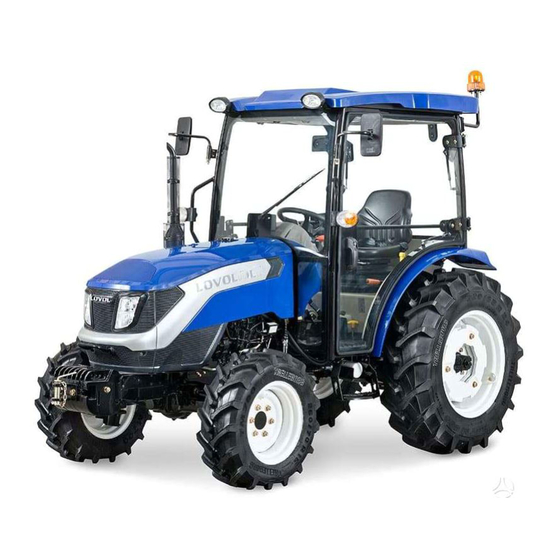
ARBOS TE series wheeled tractors. TE series wheeled tractors include TE4043C, TE4043R and ARBOS2040. The LOVOL TE, ARBOS TE series wheeled tractor is a kind of multi-purpose medium-sized agricultural wheeled tractor, which is featured by compact structure, convenient operation, flexible steering, large traction force, wide application and convenient maintenance. - Page 27 Operating Instructions 3.2.2 Instrument and Switch Combination instrument 1. Water temperature gauge; 2. Tachometer; 3. Timer; 4. Fuel gauge; Fig.3-2 Combination Instrument The meaning of each indicator light of instrument, the specification and color of the indicator light Engine tachometer After the engine is started, the indicated value refers to the working speed of the engine.
- Page 28 Operating Instructions Coolant temperature gauge Mark the engine coolant temperature value with scales, the pointer moves from left to right, where the red area is the high temperature area. Fig. 3-6 Coolant Temperature Meter Fuel gauge The fuel gauge indicates the amount of oil in the fuel tank with scales. The pointer points to the rightmost position;...
- Page 29 Operating Instructions Air pressure warning lamp (Red) For models with air brake, when air pressure of the brake system is lower than 0.40MPa, the light will light up. It indicates that the brake air line is faulty or the air pressure alarm is broken and shall be overhauled.
- Page 30 Operating Instructions Parking brake indicator (Red) When the handbrake is not pulled up, the light is on, and the alarm flashes at a frequency of 1Hz. Fig. 3-16 Parking brake indicator Steering low voltage warning lamp (Red) When this light is on, it indicates low steering pressure of tractor. Fig.
- Page 31 Operating Instructions Combination switch Low beam switch High beam switch Double flash switch Right turn signal switch Left turn signal switch Fig. 3-19 Combination Switch 1. Knob A is used to switch on and off the high and low beam. When the knob A is being rotated, the switch corresponding to the position to which triangle B points is turned on.
- Page 32 Operating Instructions S/N1: PTO switch, which has a built-in limit function. Press the limit downward, and press the switch downward in direction A as shown in the Fig. 3-21 at the same time to turn on the switch; Press the switch downward in direction B as shown in the Fig. 3-21 to turn off the switch. S/N2: park regeneration switch.
- Page 33 Operating Instructions Fig. 3-23 Rocker Switch Combination S/N5: work light switch. Press the switch downward in direction A as shown in the Fig. 3-21 to turn on the switch. At this time, the rear lights of the entire vehicle are all on; Press the switch downward once in direction B as shown in the Fig.
-
Page 34: Starting Of Engine
Operating Instructions Ignition Lock Turn the preheat starting switch clockwise to ACC position to turn on the auxiliary appliance, turn it clockwise to ON position to turn on the control circuit,and turn clockwise to H position to turn on the preheating device. - Page 35 Operating Instructions Confirm that the driver is sitting on the seat and the seat switch is turned on; For new tractors and those tractors that have been overhauled or have been left unused for a long time, the air in the oil line shall be exhausted before starting to ensure the smooth starting of the diesel engine.
- Page 36 Operating Instructions immediately after the engine is started. At this time, the key will automatically return to "ON" position. Preheat starting (only for models with preheat circuits): Preheat starting can be used when cold starting is difficult at low temperature [-5° C (Celsius degree) below].
-
Page 37: Starting Of Tractor
Operating Instructions 3.4 Starting of Tractor When the engine is in low-speed state, depress the clutch pedal and then shift the transmission shift lever to the required gear. Put down the parking brake handle. Honk the horn and observe whether there are obstacles around the vehicle. ... -
Page 38: Shift Of Tractor
Operating Instructions 3.6 Shift of Tractor 3.6.1 8+8 shuttle gear: The main and auxiliary transmission are operated by 1 control lever respectively to achieve the operation of 8 gears. Four gear levels (1, 2, 3, 4,) can be obtained by operating the main shift lever, 2 speed zones (L refers to low speed zone while H high speed zone) can be obtained by operating the auxiliary shift lever B. -
Page 39: Use Of Front Drive Axle
3.8 Use of front Drive Axle LOVOL TE, ARBOS TE series wheeled tractors are appropriate for field heavy load operations or working on wet and soft soil. If driven only by the rear wheels, the traction performance of the tractor may be insufficient. -
Page 40: Tractor Stopping And Engine Shutdown
Operating Instructions Warning: 1. Ensure that the brake works normally before dispatching the vehicle each time.Otherwise major accidents such as brake failure will occur; 2.When the tractor is running on the road, be sure to interlock the left and right brake pedals to prevent the tractor from deviating or even rolling over during braking, causing casualties. -
Page 41: Use, Disassembly And Assembly Of Tires
Operating Instructions 3.11 Use and Disassembly of Tire 3.11.1 Use of Tire Tire is an important part of tractor, please pay attention to the use and maintenance of tire to prolong its service life as much as possible. Tires have specified load value. - Page 42 Operating Instructions 3.11.2 Removal and Installation of Tires Tyre dismounting Professional tire charger or professional manual tire mounting equipment shall be used for tire removal and installation. Knocking and beating with sharp and hard tools (such as screwdriver) and sledgehammers is strictly prohibited, so as to avoid puncturing the tire or damaging the bead and rim.
-
Page 43: Use Of Counterweight
Operating Instructions Warning: It is strictly prohibited to remove the connecting bolts between the tire, the drive hub and the rim during inflation, otherwise it may fly out and hurt people. 3.12 Use of Counterweight The counterweight shall be increased or decreased based on the operating requirements of tractors. The counterweight shall be added when there is need to increase the traction during dry field operations and transportation operations;... -
Page 44: Adjustment Of Driver's Seat
3.13 Adjustment of Driver’s Seat 1. Driver's seats of TE series tractors can be adjusted forward and backward. During adjustment, pull the adjustment handle below the left side of the driver's seat outwards (as shown in the Fig. 3-13) and move the driver's seat forward or backward at the same time. -
Page 45: Outer Side Plate Of Tractor
Operating Instructions 3.14 External Structure of Tractor The external structure of tractors mainly includes an engine hood, a cab, a mudguard, an instrument panel, a floor and accessories. 3.14.1 Engine Hood (usage of special tools for opening the hood) The engine hood is of gracefully streamlined sheet metal structure. To open the hood, insert the the locking handle on the left side of the special hood opening pull rod and screw it in clockwise. - Page 46 Operating Instructions but also serves as decoration and sealing. 3.14.3 Cab (optional) Tractor cab consists of frames and glass. The frame is welded by section steel pipes and then installed with curved glass. 3.14.7 Arrangement and Usage of HAVC ● Overall arrangement of HAVC Fig.
- Page 47 Operating Instructions Fig 3-* Schematic Diagram of Heating Control Panel 3.14.8 Rollover Protection System (ROPS) 1. The ROPS of the tractor is a frame welded by rectangular pipes, which can flip backward fold. 2. The ROPS can be installed in the middle of the tractor, which can slide forward and fold. (Normal state)
- Page 48 Operating Instructions (folded state) Fig. 3-14 ROPS Warning: 1.When folding the safety frame, ensure the tractor is on a flat road, and please pull up the parking brake handle, stop the engine and pull out the key; 2. Fold ROPS (rollover protection mechanism) only when absolutely necessary, such as through buildings, orchards or vineyards.
- Page 49 Operating Instructions Cab type: 1. Front axle 2. Brake clutch pedal shaft 3. Brake clutch rotation shaft 4. Rear axle 3.14.10 How to Pull Tractors When the tractor gets stuck in mud or breaks down and needs to be towed, it can be achieved by using the front towing lug of the tractor, connecting the front towing lug of the tractor and the tow tractor with reliable and firm wire ropes or other ropes of sufficient strength, and locking pin 1 to ensure safety.
-
Page 50: Use Of Tractor Working Device
Operating Instructions 3.15 Use of Tractor Working Device The semi-split hydraulic lifting system is adopted for TE series tractors and provided with two adjustment modes: position adjustment and height adjustment. The lifting and lowering of farm implements are achieved by operating the control handle of the distributor. Press the handle forward to lower the farm implements;... - Page 51 Operating Instructions Note: The position of the two return stoppers on the push rod is adjusted according to agronomic requirements and farm implements equipped when they are used. The lifting height of farm implements varies with the different position of the stopper on the push rod. The lifting and lowering height of farm implements are controlled by the lifting and lowering stoppers respectively.
- Page 52 Operating Instructions 3.15.4 Use of Multiway Valve Hydraulic Output Device The tractor may not be equipped with one or two slide valve type hydraulic output multi-way valves as required. The two valve plates are operated by two operating handles C and D respectively to control two dual-acting cylinders on the machine tool.
- Page 53 Operating Instructions Multi-way valve Multi-way valve assembly 1 - Single and double action conversion screw "E" Important: 1. In case that the hydraulic output device is not in use, the joint seat shall be covered with a sealing cover to avoid dust. 2.
- Page 54 Operating Instructions 3.15.6 Use of Suspension Mechanism During the plowing operation, the longitudinal and transverse adjustment of the plow shall be made to ensure the consistent tillage depth of the front and rear plow-shares. Longitudinal adjustment: Adjust the length of upper pull rod A to keep the plow frame longitudinally horizontal to achieve the same tillage depth among plow-shares.
- Page 55 Operating Instructions 3.15.7 Dimensional Drawing of Suspension System [Unspecified dimension unit: mm] Fig. 3-18 Dimensional Drawing of Suspension System...
- Page 56 Operating Instructions 3.15.7.1 Running-in of Power Take-off Shaft The TE EC series tractor is equipped with a two-speed power take-off shaft with a rotating speed of 540/1000 (r/min). The operation steps of the power take-off shaft are as follows: Ensure that the PTO clutch switch is turned off, i.e., in the "0" position, and can be controlled by the dashboard.
- Page 57 3.15.8.4 Rear Trailer Socket The electrical system of TE series tractors is of 12V (volt) negative grounding two-wire system. See Fig. 3-19 for the composition and circuit of the electrical system. Rear trailer socket: in order to make it convenient to add trailer signal lights when tractors are equipped with trailers, this vehicle is equipped with rear trailer socket, and a bolt is equipped in the spare parts box.
- Page 58 Operating Instructions 3.16.6 Use and Adjustment of Electrical System The electrical system of this tractor adopts double-wire system, negative ground wire, system voltage 12V. The whole vehicle circuit is shown in Figures 3 - 5, 3 - 6 and 3 - 7. 3.16.6.1 Composition of Electrical Equipment Tractor electrical equipment is mainly used to ensure the start of tractor, monitoring the working condition of diesel engine, and illumination and signal when tractor works.
- Page 59 Operating Instructions Notes: 1. When charging, ensure that the air in the room is unblocked and away from open flames, and do not splash electrolyte on human body or clothes, so as to avoid accidental injury; 2. During charging, the electrolyte temperature shall not be higher than 45℃. If it reaches this temperature, in order to prevent accidental danger, the charging current shall be halved or stopped to cool, but the charging time shall be extended accordingly;...
- Page 60 Operating Instructions Instrument The tachometer and coolant temperature meter are mainly used to monitor the working condition of diesel engine. The fuel gauge is used to monitor the remaining condition of diesel oil level. The hour meter is used to record the working hours of the engine.
- Page 61 Operating Instructions...
- Page 62 Operating Instructions...
-
Page 63: Running-In Of Tractor
Operating Instructions 3.1 Running-in of Tractor Before putting into operation, the tractor shall operate for a period of time under the specified lubrication, speed and load conditions, and at the same time, necessary inspection, adjustment and maintenance shall be carried out to normalize the technical state, which is called running-in. 3.16.1Preparations Prior to Running-in ... - Page 64 Operating Instructions lower the suspension mechanism for several times to observe if there is any abnormality. Then, hang a heavy object with a mass of about 300kg or a matching farm implement with equivalent mass on the suspension mechanism, enable the engine to run in the big throttle position, operate the distributor handle, and lift and lower the suspension mechanism in the whole stroke for no less than 20 times.
- Page 65 Operating Instructions screen, diesel filter, oil filter and air filter. After replacing the diesel filter and oil filter element, inject new lubricating oil according to the technical requirements. Drain the oil from the drive system and front drive axle while it is hot, and add the appropriate amount of light diesel oil or kerosene.
-
Page 66: Common Faults And Troubleshooting Methods Of Tractor
Operating Instructions 3.17 Common Faults and Troubleshooting Methods of Tractor 3.17.1 Faults and Troubleshooting Methods of Chassis 3.17.1.1 Faults and Troubleshooting Methods of Clutch Table 3-3 Faults and Troubleshooting Methods of Clutch Fault Troubleshooting methods Failure cause symptom (1) There is oil stain on the friction plate and pressure plate;... - Page 67 Operating Instructions 3.17.1.2 Faults and Troubleshooting Methods of Transmission Table 3-4 Faults and Troubleshooting Methods of Transmission Fault symptom Failure cause Troubleshooting methods 1. Difficulty in (1) The clutch is not disengaged completely. (1) Troubleshoot according to clutch gear (2) The gear shift interlocking lever is too long. troubleshooting methods engagement or (3) The gear shift lever fork head is seriously...
- Page 68 Operating Instructions 3.17.1.3 Rear axle and brake faults and troubleshooting methods Table 3-5 Faults and Troubleshooting Methods of Rear Axle and Brake Fault symptom Failure cause Troubleshooting methods (1) The bearing clearance of small bevel gear (1) Adjust as required. is too large.
- Page 69 Operating Instructions 3.17.1.4 Travel system faults and troubleshooting methods Table 3-6 Faults and Troubleshooting Methods of Travel System Fault symptom Failure cause Troubleshooting methods (1) The front wheel rim or spoke plate is (1) Correct the front wheel rim or severely deformed.
- Page 70 Operating Instructions 3.17.1.5 Hydraulic steering system faults and troubleshooting methods Table 3-7 Faults and Troubleshooting Methods of Hydraulic Steering System Fault Failure cause Troubleshooting methods symptom (1) The rubber rings at all pipe joints are damaged or the (1) Replace the rubber ring or bolts are loose.
- Page 71 Operating Instructions (1) The clearance between the valve core and the valve (1) Replacement sleeve is too large. (2) Replacement (2) The clearance between the linkage shaft and the pin (3) Replacement Insensitive is too large. (4) Replacement steering (3) The clearance between the linkage shaft and the rotor is too large.
- Page 72 Operating Instructions Fault Failure cause Troubleshooting methods symptom Farm (1) Oil filter clogging (1) Clean or replace the filter element implement (2) The air enters the oil suction pipe. (2) Eliminate the air leakage at the joint and jittering (3) The gear oil pump fails. O-ring.
- Page 73 Operating Instructions 3.17.2 Faults and Troubleshooting Methods of Electrical System 3.17.2.1 Faults and Troubleshooting Methods of Engine Table 3-10 Faults and Troubleshooting Methods of Engine Faults Fault cause Troubleshooting (1) The battery capacity is insufficient. (2) The cable joint is loose and the ground (1) Charge the battery as required.
- Page 74 Operating Instructions 3.17.2.2 Faults and Troubleshooting Methods of Generator Tab. 3-11 Faults and Troubleshooting Methods of Generator Faults Fault cause Troubleshooting (1) The connecting wire is improper or (1) Check and repair the circuit. Power broken. The connection is poor. (2) Check and repair the generator assembly generation (2) There is an open circuit in the rotor coil.
- Page 75 Operating Instructions (1) There are impurities in the electrolyte. (1) Replace the battery (2) There is a short circuit in the external (2) Check the shorted part and eliminate the wires of the battery. fault. (3) There is electrolyte on the surface of the (3) Use alkaline water or warm water to wash battery, causing a short circuit between the battery surface and terminal so as to...
- Page 76 Operating Instructions 3.17.2.5 Faults and Troubleshooting Methods of Lighting Table 3-14 Faults and Troubleshooting Methods of Lighting Fault Failure cause Troubleshooting methods symptom (1) The circuit is open; and the Headlamp short-circuit fuse is blown. (1) Repair and close the circuit. without (2) The dimmer switch is in poor contact (2) Overhaul and replacement...
-
Page 77: Accessories, Spare Parts And Vulnerable Parts
Accessories, spare parts and vulnerable parts 4 Accessories, Spare Parts and Vulnerable Parts 4.1 Accessories and Spare Parts 4.1.1 Details of Accompanying Tools Table 4-1 Details of Accompanying Tools Code Name Qty. Remarks JB/T 7942.1 Lever-type grease gun A100 QB/T 2564.4 Slot head screwdriver 1×... - Page 78 Accessories, spare parts and vulnerable parts 4.1.3 List of Accompanying Documents Table 4-3 Details of Accompanying Documents S/N Code Name Qty. Remarks Accompanying Technical Documents for Engine DOCUMENTS OF ENGINE Qualified Certificate From supporting manufacturer of the QUALIFIED CERTIFICATE FOR engine TRACTOR Parts Diagram of the Tractor...
-
Page 79: Maintenance
Technical maintenance of tractors as early as possible can effectively prolong the service life of machines and reduce accidents. According to the total working hours, the technical maintenance of TE series tractors includes: every shift (10h), every 50h, every 200h, every 400h, every 800h, every 1600h, special maintenance in winter and long-term storage. - Page 80 Maintenance Instructions 5.1.2 Technical Maintenance Every 50h (1) Complete all procedures of technical maintenance per shift. (2) Check the oil level of oil-bath air filter and remove dust. (3) Check the tightness of the fan belt (when the belt is pressed by hand, the sag is (15~20) mm), and adjust it if necessary.
- Page 81 Maintenance Instructions (6) Check and adjust the engine valve clearance. (7) Check and adjust the fuel injection pressure of the fuel injection pump. (8) Clean the fuel tank and the filter in the fuel tank. (9) Maintain the diesel engine according to the requirements of "Level Ⅳ technical maintenance" in the Operation Manual of Diesel Engine.
- Page 82 Maintenance Instructions Table 5-1 Maintenance of TE Series Tractors Maintenance parts Operations Points Maintenance interval Engine oil pan Check the liquid level Per shift Oil-bath air filter Check the liquid level Per shift Air pump Check the liquid level Per shift...
-
Page 83: Adjustment Of Clutch
Maintenance Instructions 5.2 Adjustment of Clutch 5.2 Adjustment of Clutch To ensure the normal operation of the clutch, the clearance between the working face of the main clutch release lever 4 and the end face of the release bearing 5 must be kept at (2 ~ 2.5) mm. -
Page 84: Adjustment Of Brake
Maintenance Instructions lubrication grease to make the lubrication grease penetrate into the bearing, take out and install it after the lubrication grease is cooled. Do not wash the release bearing in gasoline or diesel, so as to prevent the lubrication grease in the bearing from being washed away. -
Page 85: Adjustment Of Central Transmission
Maintenance Instructions Note: The tractor's left and right brake pedal strokes must be adjusted to the same, otherwise the tractor will deflect sharply to one side during emergency braking, which will cause accidents. 5.4 Adjustment of Central Transmission 5.4.1 Adjustment of Pre-tightening of Cone Bearing After a period of use, the original preload will gradually disappear due to bearing wear, and there will be clearance between two bearings. - Page 86 Maintenance Instructions 5.4.2 Adjustment of Contact Mark and Backlash of Bevel Gear Pair When impact or noise is generated due to excessive wear or abnormal contact mark in tooth surface during the use of the spiral bevel gear pair, or when a new bevel gear pair is replaced, the contact mark and backlash should be readjusted and checked regularly.
- Page 87 Maintenance Instructions Table 5-2 Adjustment of mark of small spiral central transmission bevel gears Mark of small spiral Mark of small spiral Mark bevel gear in forward bevel gear in reverse Adjustment description and illustration description gear gear In forward gear, the total length of the mark on the concave surface of the small spiral Normal bevel gear is not less than 60% of the tooth...
- Page 88 Maintenance Instructions Mark of small spiral Mark of small spiral Mark bevel gear in forward bevel gear in reverse Adjustment description and illustration description gear gear Reduce adjusting washer at front bearing sleeve of the second shaft to make the small spiral bevel gear move...
-
Page 89: Adjustment Of Steering System
5.6.1 Precautions for Use of Full Hydraulic Steering System (Hydraulic Check) Lovol four-wheel drive tractor adopts full hydraulic steering, as shown in the figure. The steering system is correctly adjusted before the tractor leaves the factory. Attention shall be paid to the following matters during use: ... - Page 90 Maintenance Instructions Adjustment of Front Wheel Toe-in 5.6.2 During the use of tractor, the front wheel toe-in changes due to the deformation and wear of steering mechanism and front axle parts. Failure to adjust in time will accelerate the wear of the front tire. Adjustment of front wheel toe-in is as follows: ...
-
Page 91: Adjustment Of Front Drive Axle
Maintenance Instructions 5.7 Adjustment of Front Drive Axle 5.7.1 Adjustment of Central Transmission of Front Drive Axle The two tapered roller bearings on the small bevel gear shaft of the front drive axle and the left and right tapered roller bearings on the differential housing are pre-tightened. -
Page 92: Use And Maintenance Of Air Filter
Maintenance Instructions 5.8 Use and Maintenance of Air Filter 5.8.1 Instructions of Filter When the filter blockage alarm indicates a warning signal or the filter works for (50~100)h, the main filter element needs to be maintained; In the case of dusty working environment, the main filter element should be maintained every 8h or per shift;... -
Page 93: Inspection Of Oil Quantity In Engine Oil Pan And Change Of Oil
Maintenance Instructions 5.10 Inspection of Oil Quantity in Engine Oil Pan and Change of Oil (1) Pull out the oil dipstick A at the front left of the oil pan and check whether the oil level is between the upper and lower scribed lines. -
Page 94: Maintenance Of Oil Filter
Maintenance Instructions 5.12 Maintenance of Oil Filter The oil filter is located in the middle on the right side of the engine, and the engine should be replaced every 200h of operation according to the technical requirements. The oil filter shall be replaced as a whole, and it must be tightened during installation. -
Page 95: Maintenance Of Fuel Tank
5.16 Inspection of Tire Inflation Pressure Check the tire pressure with a barometer. See the technical specification list of TE series tractors for tire inflation pressure. Note: Too high or too low tire pressure will shorten the service life of tires and affect the driving control of tractors and cause accidents. -
Page 96: Add The Mark Position Of Lubrication Points And The Description Of Safety Filling Process
Maintenance Instructions Fuel System 5.18 Exhaust of If the tractor is out of service for a long time or the diesel filter element is being replaced, and when the fuel tank is empty, air may enter the fuel pipeline. The air in the fuel system will make it difficult to start the engine. -
Page 97: Battery
Maintenance Instructions 5.20 Battery 5.20 Maintenance of Maintenance-free Battery Inspection of battery condition Maintenance-free battery does not need special maintenance ordinarily. Observe the hydrometer observation hole: green: sufficient power; black: insufficient power; white: basically no power (Fig. 5-1). Charge the battery when the observation hole is black;... -
Page 98: Storage
Storage 6 Storage Tractors must be properly kept and sealed after completing farmland operations, or when they are parked for a long time (more than one month) for some reasons. Tractors shall be kept in a good environment to prevent rusting, aging and deformation of the parts. -
Page 99: Storage Of Tractor
Storage 6.2 Storage of the Tractor 6.2.1 Before storage, carefully check the tractor, eliminate the existing faults and keep it in good condition. Clean the appearance of the tractor. 6.2.2 Drain the antifreeze and anti-rust fluid in the radiator, cylinder block and water pump, lubricating oil in the drive system and hydraulic oil in the hydraulic system. -
Page 100: Maintenance Of Tractor During Sealing Period
Storage 6.3 Maintenance of the Tractor during Storage 6.3.1 Tractors must meet the above requirements of tractor storage during storage. 6.3.2 Check the tractor and its parts for rusting, corrosion, aging, deformation and other abnormal phenomena every month, and eliminate any problems found in time. 6.3.3 Every 2 months, rotate the engine crankshaft (10 ~ 15 turns) to prevent internal rusting. -
Page 101: Delivery, Acceptance And Transportation
Delivery, Acceptance and Transportation 7 Delivery, Acceptance and Transportation 7.1 Delivery and Acceptance The users shall check and accept the purchased tractors while purchasing, focusing on the following aspects: Accompanying documents are complete The accompanying documents include: Operation Manual for Tractor, Product Qualification Certificate, Three Guarantees Service Certificate, Packing List of Accompanying Items, "Engine Accompanying Technical Documents"... - Page 102 Delivery, Acceptance and Transportation If necessary, place the safety frame in the folding position and fix it firmly. When crossing culverts and bridges, pay full attention to whether there is superelevation, and fully slow down when turning. When unloading, release the hand brake first, shift to the forward gear, and slowly drive downward at the lowest speed.
-
Page 103: Technical Specifications
Product executive standard: Q/LWZ 001 LOVOL Wheeled Tractor Diagram of Product Model and Factory Number Location Engraving position 8.2 Main Technical Specifications for Four-wheel Drive Models of TE Series Tractors Table 8-1 Main Technical Specifications for Four-wheel Drive Models of LOVOL-TE Series Tractors LOVOL Model Unit... - Page 104 Technical Specifications LOVOL Model Unit TE4043C TE4043R Minimum With unilateral braking 3.0± 0.3 turning circle Without unilateral braking 3.5± 0.3 radius Structure mass Without counterweight 1780 1671 Minimum With driver, full of oil and water, without 1850 1752 service mass...
- Page 105 Technical Specifications LOVOL Model Unit TE4043C TE4043R 1.97 2.96 speed 4.66 6.42 Forward gear 9.09 High 13.70 speed 21.52 29.67 Shuttle gear Km/h 1.74 2.63 speed 4.13 5.69 Reverse gear 8.06 12.16 High speed 19.09 26.33 —— Clutch Ten-inch dual-acting clutch Double shaft, mechanical gear ——...
- Page 106 Technical Specifications LOVOL Model Unit TE4043C TE4043R Rear-mounted three-point suspension type I Upper suspension point, connecting pin × length: φ22 × Suspension mechanism Lower suspension point, connecting hole × width: φ25.4 × —— Adjustment method of tillage depth Liquid level control...
- Page 107 Technical Specifications LOVOL Model Unit TE4043C TE4043R Model —— 95D31 Voltage Battery Capacity A· h Qty. —— Headlamp —— 12V, 55W, combined Front turn signal lamp —— 12V, 35W, 2 pcs 12V, brake light 21W, turn signal Lighting and ——...
-
Page 108: Dismantling And Disposal
Dismantling and Disposal 9 Dismantling and Disposal For your personal safety and social environment protection, please hand over the machine to a recycling company with a professional license for dismantling if the whole service life of the machine expires. Please dismantle from top to bottom, first outside and then inside. -
Page 109: Warranty Items
10 Warranty Items 10.1 Basis of Product Warranty LOVOL TE、ARBOS TE series TE404C, Te404R and ARBOS 2040 wheeled tractors are guaranteed according to the following documents and regulations. Provisions on the Warranties for the Repair, Replacement and Return of Agricultural Machinery Products formulated by the State Economic and Trade Commission in 1998, Document No. -
Page 110: Appendix
Appendix Appendix 11 11.1 Oil and Solution for Tractor Table 11-1 Oil and Solution for Tractor Parts requiring Oil and solution oil and solution D-975 fuel recommended by American Society of Testing and Materials. Use 2-D grade oil at Fuel tank normal temperature, and use 1-D grade oil when the temperature is lower than 5℃. -
Page 111: Tightening Torque Table Of Main Bolts And Nuts
Appendix Important: The cooling water should be clean soft water (such as rainwater, snow water or river water, etc.). If hard water (such as well water, spring water, etc.) is used, it should be boiled in advance, and added into the water tank after precipitation, so as not to damage the water tank. -
Page 112: Rolling Bearing Of Trailer
Appendix 11.3 Tractor Rolling Bearing Table 11-3 List of Tractor Rolling Bearings Bearing Shaft bearing Code Installation position Qty. code name Deep groove ball GB/T 276 6203-Z Front end of clutch shaft bearing Deep groove ball Front end of power output GB/T 276 6006 bearing... - Page 113 Appendix Bearing Shaft bearing Code Installation position Qty. code name Deep groove ball GB/T 276 6307 Outer end of short axle shaft bearing Deep groove ball Front end of transmission GB/T 276 6207N bearing case first shaft Cylindrical roller Rear end of transmission GB/T 283 NT206E bearing...
- Page 114 Appendix Bearing Shaft bearing Code Installation position Qty. code name Needle roller GB/T 5846 K253120 Transfer case output shaft bearing Needle roller GB/T 5846 K283327 III~IV gear driven gear bearing Needle roller GB/T 5846 K303527 High and low gear fixed gear bearing Angular contact GB/T 292...
-
Page 115: Trailer Chassis Sealing Element
Appendix 11.4 Tractor Chassis Seals: Table 11-4 List of Tractor Chassis Seals Component Specification Installation position Qty. B35× 55× 8 Front end of first shaft Inside the bearing cover of GB/T 9877.1 FB35× 55× 8 the power output shaft Rotating shaft lip seal ring B50×... - Page 116 Appendix Component Specification Installation position Qty. GB/T9877.1 Steering gear B30× 45× 8 Steering vertical arm shaft Rotating shaft lip seal ring JB/T2600 PD42× 62× 10 Lifting shaft Framework oil seal 10× 13.5 Oil drain plug 10× 13.5 Cylinder head JB/T 982 Sealing gasket 18×...
- Page 117 Appendix Component Specification Installation position Qty. JB/T2600 SG30× 45× 8 Transfer case output shaft Framework oil seal 12.5× 1.8G Transfer case fork shaft Transfer case Front end of rear sheath GB/T3452.1 36.5× 2.65G weldment O-ring Rear end of rear sheath 53×...
-
Page 118: Supporting Agricultural Tools For Lovolte And Arbos 2040 Series Tractors
Appendix 11.5 Supporting Agriculture Tools of LOVOL TE Series Tractors Table 11-5 Supporting Agriculture tools of LOVOL TE Series Tractors Supporting machines Machines and Category Tractor model Main technical parameters and tools Tools model Suspended three-furrow 1L-320 Tillage depth (140~180) mm... - Page 119 Appendix Supporting machines Machines and Category Tractor model Main technical parameters and tools Tools model Working width 1,250m, tillage TE254 1GM-2/3 depth (120 ~ 150) mm Stubble Working width 1,400m, tillage Harvesting machinery SGTN-140 cleaner depth (120 ~ 150) mm TE304 TE354 Speed of stubble cutter: 400...
-
Page 121: User Information Feedback Sheet
Dear Customer: Thank you very much for your patronage, purchasing and using LOVOL-TE series wheeled tractors. We are willing to serve you wholeheartedly by solving your problems during usage in a timely and effective manner and meeting your requirements to the maximum extent.
Need help?
Do you have a question about the TE Series and is the answer not in the manual?
Questions and answers