Table of Contents
Advertisement
Quick Links
Product Information
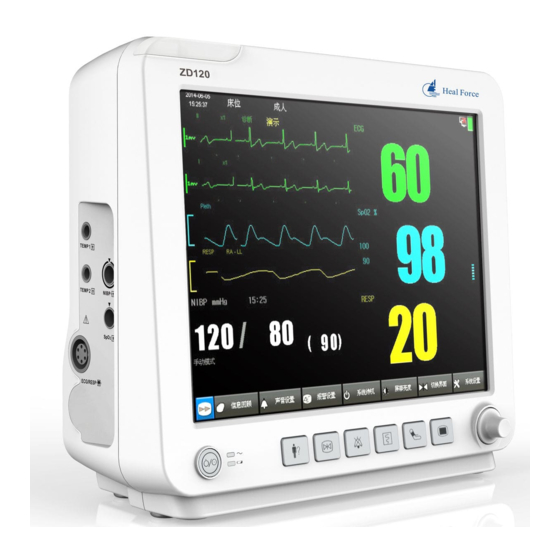
Product model: ZD120
Product name: Patient Monitor
Manufacturer
Shenzhen Hexin ZONDAN Medical Equipment Co., Ltd.
Registered/Production address:
Floor 14, Block D, Dianlian Technology Building,the Crossing between South Circle
Road and South Fuli Road,Guangming District, 518106 Shenzhen PEOPLE'S
REPUBLIC OF CHINA
Tel: +86 755 26865970
Edition
Second Edition: October 2021
Version: V1.2
MEDHealth supplies (Pty) Ltd
All Rights Reserved.
Distributor
MEDHealth Supplies (Pty) Ltd
Corner of Barbara and North Reef Road
Elandsfontein, Henville, 1429, Germiston, Johannesburg, Gauteng, South Africa
Reg No.: 2021/385832/07
E-mail: admin@medhealthsup.com
Regulatory and Safety Specifications
Standard
The product is made under the ISO13485 quality system certified by TUV PS. The
product has passed the CE certification.
Declaration
The ZD120 Patient Monitor is a Class IIa device and complies with the requirements of
the Council Directive 93/42/EEC concerning medical devices and carries CE-marking
accordingly.
Authorized EU Representative
Shanghai International Holding Corp.GmbH (Europe)
Eiffestrasse 80, 20537 Hamburg, Germany
Tel: 0049-40-2513175
Fax: +86 755 26860497
Telephone: +27 10 013 3010
Fax: 0049-40-255726
I
ZD120 User's Manual
Version: 1.2 October 2021
Advertisement
Table of Contents
Troubleshooting

Related Manuals for ZONDAN ZD120

Summary of Contents for ZONDAN ZD120
- Page 1 The product is made under the ISO13485 quality system certified by TUV PS. The product has passed the CE certification. Declaration The ZD120 Patient Monitor is a Class IIa device and complies with the requirements of the Council Directive 93/42/EEC concerning medical devices and carries CE-marking accordingly.
- Page 2 Explanation of Symbols The following symbols appear on the monitor and its packaging. Table 1 Monitor and Packaging Symbols Symbol Description Symbol Description Caution, consult CE mark accompanying documents Keep dry Temperature limitations 107.4kPa Atmospheric pressure Humidity limitations limitations 22kPa Keep upright Fragile, handle with care Recovery...
- Page 3 Note, Check the documents Electronic Products Use limit Use Limit (20 years) Fuse Safety Standards The following table describes the safety standards of the ZD120 Patient Monitor. Table 2 Safety Standards Parameter Specification Class I, anti-shock, externally and internally powered Protection class...
- Page 4 Product Support and Warranty Information MEDHealth Supplies warranties the ZD120 Patient Monitor for 12 months. Keep the packing case for transport, storage, or maintenance. ZONDAN is responsible for the safety, reliability, and performance of the monitor when the: • Product is assembled, upgraded, altered, or maintained by authorized service representatives.
- Page 5 A Caution calls attention to a condition or possible situation that could damage or destroy the product or the user. Warning A Warning calls attention to a condition or possible situation that could cause injury to the user and/or patient. ZD120 User’s Manual Version: 1.2 October 2021...
- Page 6 Safety Requirements Note — The safety indications in this chapter apply to general monitor use. Safety indications in other chapters apply to specific monitor measurements. Follow the instructions in this user manual when using the monitor. However, conventional medical practices always supersede this document. Significance of safety requirements set forth here in this manual is not in order of reading sequence.
- Page 7 To reduce the hazard of burns in high-frequency surgical neutral connections, the leads and connectors must be located away from the surgical site. Keep cables away from other devices. Ensure that qualified service representatives annually calibrate and maintain the monitor. ZD120 User’s Manual Version: 1.2 October 2021...
- Page 8 Periodically check all reusable accessories for damage. Replace and dispose of damaged accessories. When necessary, according to your local hospital waste disposal regulations. ECG electrodes are disposable accessories. Always properly dispose of ECG electrodes according to your local hospital waste disposal regulations. Clean and sterilize the monitor and accessories according to local requirements.
-
Page 9: Table Of Contents
3.2.4 Export data ........................13 3.2.4.1 Software program upgrade .................... 13 3.2.5 Demo mode ........................14 3.2.6 Standby mode ........................14 3.3 Patient information .......................... 15 3.3.1 Input name and bed number ..................... 16 ZD120 User’s Manual Version: 1.2 October 2021... - Page 10 3.3.2 User settings ........................16 3.3.3 Clear stored data ....................... 16 3.3.4 Use default values ......................16 3.4 Information review .......................... 17 3.4.1 NIBP review ........................17 3.4.2 Alarm event review ......................17 3.4.3 Trend list display ......................18 Chapter 4 Alarms ........................19 4.1 Alarm Types ..........................
- Page 11 B.7 Physical specifications ........................65 B.8 Environmental Specifications ......................66 B.9 Interface Specifications ........................66 C Alarm ............................ 67 C.1 The physiological alarm information ....................67 D Glossary ..........................71 D.1 Terminology Definitions......................... 71 ZD120 User’s Manual Version: 1.2 October 2021...
- Page 12 E Electromagnetic Compatibility ..................... 72 E.1 Instructions for Use ......................... 72 E.2 Guidance and Manufacturer's EMC Declaration ................74 E.2.1 Electromagnetic Emissions for all Equipment and Systems ..........74 E.2.2 Electromagnetic Immunity for all Equipment and Systems ..........74 E.2.3 Electromagnetic Immunity for Equipment and Systems not Life-Supporting ....75 E.2.4 Recommended Separation Distances for Equipment and Systems not Life-Supporting .
-
Page 13: Chapter 1 Overview
What you see on the screen, how the menus appear and so forth, depends on the way it has been configured for your hospital. 1.1 Indications for Use The ZD120 Patient Monitor is for use by healthcare professionals whenever there is a need for monitoring the physiological parameters of patients. 1.2 Intended Use The ZD120 Patient Monitor is intended for monitoring, recording, and alarming of multiple physiological parameters of adults, pediatrics, and neonates in healthcare environments. - Page 14 User’s Manual MHSZD120 Version: 1.2 October 2021...
-
Page 15: Chapter 2 General Description
Chapter 2 General Description This chapter describes how to set up and begin using the ZD120 Patient Monitor. 2.1 Before You Begin Before patient monitoring, ensure that the monitor is in good condition and used in the proper environment. 2.1.1 Unpacking the Equipment 1.Unpack the equipment and ensure that you have the following:... -
Page 16: Networking Capabilities
The monitor communicates with the ZONDAN Central Monitoring System via the Ethernet ports on the back of the monitor. Network setup of the ZD120 Patient Monitor is not user configurable. Please contact your service personnel. -
Page 17: Product Description
Alarm indicator information Press and hold for two seconds to turn the monitor on or off. Power indicator Power ON/OFF f light (Green) Power on the green light stays on; Power off: No light ZD120 User’s Manual Version: 1.2 October 2021... -
Page 18: The Rear Panel
AC Power LED (Green) AC Power indicator Connect AC Power: the green light stays on. No AC Power: No light; Charging LED (Yellow) Connect AC Power: No battery: Yellow, flash every second. Charging indicator Battery charging: the yellow light stays on. Battery finished charging: no light. -
Page 19: The Side Panel
Used for power supply and Module box contract date transfer 2.2.3 The Side Panel The side panel of the main unit is shown in Fig. 2-3. Foot pad Figure 2-3 Side Panel ZD120 User’s Manual Version: 1.2 October 2021... -
Page 20: Screen Display
The following table describes the side panels. Table 2-3 Side Panels Item Number Item Name NIBP NIBP connector SpO2 SpO2 connector 2.3 Screen Display The monitor’s display is a TFT color LCD, which displays the patient’s monitoring parameters, monitoring waveforms and their status, current monitoring time and other information. When the monitor is set to the body temperature interface, it can communicate with the ear thermometer to transmit measurement data through Bluetooth connection. - Page 21 Figure 2-4 Example of Screen Display The following table describes the screen display. Table 2-4 Screen Display Description Description Description Time display area Status information area Patient information area Waveform area ZD120 User’s Manual Version: 1.2 October 2021...
-
Page 22: Time Display Area
Technical alarm area Menu area Alarm status prompt area Parameter area Physiological alarm area 2.3.1 Time display area The time display area displays the current monitoring time. 2.3.2 Patient information area The patient information area is located at the top of the interface and displays relevant information about the monitored patient. -
Page 23: Physiological Alarm Area
Battery is installed Wireless The wireless network connection is network successful AC power AC power connected Note - The status information area can’t display AC power and battery power at the same time. ZD120 User’s Manual Version: 1.2 October 2021... -
Page 24: Waveform Area
2.3.7 Waveform area If the user selects the SpO waveform interface, it displays the SpO monitoring parameter waveform. 2.3.8 Menu area The menu area is located at the bottom of the main interface and displays the function setting menu. Table 3-7 Description of function keys Status Icon Description... -
Page 25: Spot Check Interface Display
1. Swipe the touch screen to view the “NIBP Trend List”. Note - The Spot check interface only displays and records the measured values of NIBP, SpO2, and PR, and the alarm function is off. ZD120 User’s Manual Version: 1.2 October 2021... -
Page 26: Large Font Interface Display
2.6 Large font interface display When the user selects the large font interface, this will display larger fonts. It is convenient for medical staff to observe the measurement parameters from a distance. Enter the large font display interface in the following steps: Method 1: 1. -
Page 27: Ecg Interface
1. Select the Main Menu button in the menu area to enter the main menu. 2. Select the ECG interface. Note - The parameters displayed on the ECG interface are HR, RR and real-time waveforms. ZD120 User’s Manual Version: 1.2 October 2021... -
Page 28: Chapter 3 Basic Operation
Chapter 3 Basic Operation This chapter mainly describes some menu operations and monitor settings. 3.1 Menu operation The monitor operates the menu through the touch screen. 3.1.1 Menu settings In the menu area, you can complete NIBP settings, system settings, interface switching, alarm settings, alarm sound settings, sound settings, system standby, trend chart display, alarm event record review, and screen brightness settings. -
Page 29: General Settings
Table 3-1 Volume and alarm silence time selection Available volume Maximum volume, medium volume, minimum Volume volume, off Alarm silence 2 minutes, 5 minutes time Maximum volume, medium volume, minimum Alarm volume volume ZD120 User’s Manual Version: 1.2 October 2021... -
Page 30: Screen Brightness
3.2.2 Screen brightness Adjust the screen brightness through the following steps: 1. Select the Main Menu button in the menu area to enter the main menu. 2. Select the corresponding screen brightness, including normal, brightness level 1, brightness level 2, brightness level 3, brightness level 4, brightness level 5, brightness level 6, brightness level 7, brightness level 8, and night. -
Page 31: Language Selection
When it prompts that the USB storage device is connected, copy the XpsBurn.txt, MHSZD120AV1S.xin, and 1.xgf configuration files to the USB disk. The monitor will automatically update software according to the configuration files; the monitor then automatically restarts and complete the software update. ZD120 User’s Manual Version: 1.2 October 2021... -
Page 32: Demo Mode
The XpsBurn.txt configuration file command is resolved as follows: – MHSZD120AV1K.xin //Version number – //1.xgf //Company LOGO configuration file – //Indicates a comment, “1.xgf” is a separate LOGO configuration file. Note - The USB data cable needs to be used in conjunction with a USB adapter, otherwise the computer system may not be compatible and can’t recognize USB. -
Page 33: Patient Information
Select the Patient Management button in the menu area to enter the user information interface, and perform the following operations: ⚫ Input name, bed number ⚫ User settings (adult, child, newborn) ⚫ Clear stored data (off, on) ⚫ Use the default value (off, on). ZD120 User’s Manual Version: 1.2 October 2021... -
Page 34: Input Name And Bed Number
Fig. 3-2 Patient information 3.3.1 Input name and bed number The user can input the patient’s name and bed number. 3.3.2 User settings Set user settings in the following steps: 1. Touch the screen to select the Patient Information button and enter the user information interface. -
Page 35: Information Review
Note - When the alarm system is powered off, the system will not erase the alarm event records. The alarm event record will not change 30s after the alarm system loses all power (AC and/or ZD120 User’s Manual Version: 1.2 October 2021... -
Page 36: Trend List Display
battery). 3.4.3 Trend list display The trend data of the monitored patients will be displayed in the trend list in the form of a list. You can view 10,000 measurement data and view the trend data SYS/ DIA, MAP, SpO2, PR (SpO2 pulse rate) every minute through the trend list. -
Page 37: Chapter 4 Alarms
Such as, ECG electrodes fall off, SpO2 sensor fall off, etc. Note — In addition to physiological alarms and technical alarms, the monitor also ZD120 User’s Manual Version: 1.2 October 2021... -
Page 38: Alarm Levels
displays some information related to system status and patient status. Prompt information is generally displayed in the technical alarm area and prompt information area. In addition, some prompt information is displayed in the parameter area, for example: NIBP related prompt information is displayed in the NIBP parameter area. The time limit of the “SpO2 sensor falls off”... - Page 39 Changing the alarm volume to a low level or turning it off during patient monitoring could result in patient danger. The most reliable method of patient monitoring combines close personal surveillance with correct operation of monitoring equipment. ZD120 User’s Manual Version: 1.2 October 2021...
-
Page 40: Flashing Leds
The auditory alarm signal sound pressure levels, which are less than ambient levels, can impede OPERATOR recognition of ALARM CONDITIONS and the ALARM SYSTEM. 4.3.2 Flashing LEDs There is an alarm LED on the front panel of the monitor. The following table describes the alarm LED colors: Table 4-2 Alarm LEDs Light... -
Page 41: Alarm Control
Choose turn ON/OFF an individual alarm. Click icon to confirm and back to previous menu. Exit the menu. Method 2: Enter individual parameter at numeric panes. The individual parameter setup will appear. Choose to turn ON/OFF alarm. ZD120 User’s Manual Version: 1.2 October 2021... -
Page 42: Silencing Alarms
Click icon to confirm and back to previous menu. Exit the menu. Note —When all audible alarms are off, pressing the Alarm Silence menu turns on alarm sounds again. The Alarm Off configuration is not saved when the monitor is turned off. When you turn the monitor on again, audible alarms are on by default. -
Page 43: Adjusting The Alarm Volume
Setting the upper limit to 100 or setting the lower limit to zero is equivalent to no alarm limit. In these instances, the screen does not display an alarm off icon. To set an individual alarm limit: Method 1: Enter System menu. Enter Alarm Setup. ZD120 User’s Manual Version: 1.2 October 2021... -
Page 44: Restoring Default Alarm Limits
Set up alarm limit at Upper Limit and low limit of SPO2, PR, SYS, DIA and TEMP. Choose “ to delete the value. Enter the value Click “ to confirm. Method 2: Enter Alarm setup at menu area , NIBP, TEMP Alarm Setup are options. Choose one parameter and press to confirm. -
Page 45: Reviewing Alarm Events
The contents of the log will no change after the alarm system has experienced a total loss of power for a finite duration. The first contents of the log will be sequentially overwritten as it reaches capacity. ZD120 User’s Manual Version: 1.2 October 2021... - Page 46 When a patient is discharged; the monitor clears the previous patient data and deletes all alarm events from the Alarm Event Review window. User’s Manual MHSZD120 Version: 1.2 October 2021...
-
Page 47: Chapter 5 Monitoring Spo
• Ensure that the light emitter and the photodetector are directly opposite each other. All light from the emitter must pass through the patient’s tissue. ZD120 User’s Manual Version: 1.2 October 2021... -
Page 48: Connecting Spo Cables
Warning At elevated ambient temperatures be careful with measurement sites that are not well perfused because this can cause severe burns after prolonged application. All listed sensors operate without risk of exceeding 41 ℃(105.8 ℉) on the skin if the initial skin temperature does not exceed 35℃... -
Page 49: Assessing Suspicious Spo
ECG. However, this does not indicate an inaccurate value. If you suspect the measured SpO value, use the pleth wave and perfusion indicator to assess the signal quality. ZD120 User’s Manual Version: 1.2 October 2021... -
Page 50: The Spo Display
5.6 The SpO Display The following figure shows an example of the Pleth wave and the SpO numeric pane. Figure 6-1 Pleth Wave and SpO Numeric Pane 1 = Pleth wave 2 = SpO numeric label 3= SpO unit 4= PR numeric label 5= PR value 6= Perfusion index numeric label 7= Perfusion index value... -
Page 51: Changing The Spo Display
Avoid placing the sensor on extremities with an arterial catheter, or intravascular venous infusion line. If a sensor is too loose, it might compromise the optical alignment or fall off. If it is ZD120 User’s Manual Version: 1.2 October 2021... - Page 52 too tight, for example because the application site is too large or becomes too large due to edema, excessive pressure may be applied. This can result in venous congestion distal from the application site, leading to interstitial edema, hypoxemia, and tissue malfunction. The SpO function of the device is calibrated to display functional oxygen saturation.
-
Page 53: Chapter 6 Monitoring Nibp
Place the cuff 2 cm-5 cm above the elbow and make sure that the cuff is in the correct position. Place the hose along the left or the right side of the patient’s arm to avoid tangling. The following figure show correct cuff placement. ZD120 User’s Manual Version: 1.2 October 2021... - Page 54 Figure 6-1 NIBP Cuff Placement Attach the cuff hose to the NIBP connector on the monitor. The hose clicks into place when seated correctly. Make sure that there is no blockage between the monitor and the hose. Press the NIBP key on the right panel of the monitor or press the NIBP menu at menu area to start or stop the NIBP measurement at any time.
-
Page 55: Measurement Limitations
6.3 The NIBP Display The following figure shows an example of the NIBP numeric pane. Figure 7-2 NIBP Numeric Pane 1 = NIBP Numeric Pane label 2 = NIBP Diastolic pressure alarm high and low limit ZD120 User’s Manual Version: 1.2 October 2021... -
Page 56: Selecting The Nibp Measurement Modes
3 = NIBP Systolic pressure alarm high and low limit 4 = Work mode (Manual mode in this example) 5 = Systolic pressure value 6 = Diastolic pressure value 7 = Mean arterial pressure value 8 = Pulse Pressure Difference 9 = Pulse Pressure Difference Value 6.4 Selecting the NIBP Measurement Modes There are three NIBP measurement modes:... -
Page 57: Selecting The Nibp Interval Time
2. Press Interval Time, a List box appears. 3. The options are: 2min, 3min, 4min, 5min, 10min, 15min, 30min, 60min, 90min, 120min. 4. Press to confirm an interval time. 5. Exit the menu. ZD120 User’s Manual Version: 1.2 October 2021... -
Page 58: Changing The Nibp Unit
Warning Under mode, prolonged measurements may increase friction between Auto Stat the cuff and patient skin which may cause purpura, ischemia, and neuropathy. Inspect the application site regularly to ensure skin quality and inspect the extremity of the cuffed limb for normal color, warmth, and sensitivity. If any abnormality occurs, place the cuff on another site or stop NIBP monitoring. -
Page 59: Changing The Nibp Alarm Settings
Never place the cuff on an area where circulation is compromised or has the potential to be compromised. Never measure NIBP on patients with sickle-cell ZD120 User’s Manual Version: 1.2 October 2021... - Page 60 disease or any condition where skin damage has occurred or is expected. Never use the NIBP cuff on a limb with an intravenous infusion or arterial catheter in place. This could cause tissue damage around the catheter when the infusion is slowed or blocked during cuff inflation.
-
Page 61: Chapter 7 Monitoring Temperature
7.2.1 Set TEMP alarm The TEMP alarm setting determines the TEMP alarm mode during monitoring. For the method of setting the TEMP alarm switch and upper and lower limits, see 5.5 “Alarm Settings”. ZD120 User’s Manual Version: 1.2 October 2021... -
Page 62: Change Temp Unit
7.2.2 Change TEMP unit You can set the body temperature unit of this monitor to Celsius (°C), or Fahrenheit (°F) as needed. The body temperature unit is displayed in the body temperature parameter area. Change the TEMP unit in the following steps: 1. -
Page 63: Troubleshooting Of Ear Thermometer
(42.3°C) The measured body temperature is lower than The LCD display shows Check whether the probe is clean, and the lower limit of the “Lo” measure again. measuring range (32.0°C) ZD120 User’s Manual Version: 1.2 October 2021... -
Page 64: Safety Information
7.6 Safety Information The disposable probe is sterile and must be operated as sterile items. See “Expiration Warning Date” on the probe package. Only use ear thermometers designated by our company. When the probe becomes loose or falls off, the temperature measurement is stopped, but there is no alarm sound. -
Page 65: Chapter 8 Review
,to check the waveform which happens in every minute earlier or later, Press ,to check the waveform which happens in every second earlier or later. press 10. Choose Waveform Speed, 6.25mm/s,12.5mm/s and 25.0mm/s are options. 11. Exit the menu. ZD120 User’s Manual Version: 1.2 October 2021... -
Page 66: Alarm Recall (Physiological Alarm)
8.3 Alarm Recall (Physiological alarm) You can review alarm events that occurred during monitoring in the Alarm Event Review window. The monitor can store 60 groups of alarm events in the system, including date; time, parameter values, and the corresponding alarm description. To review alarm events: Enter Review menu. -
Page 67: Chapter 9 Recording
2. Pull at least 25mm of the paper out of the door, use screwdriver fix the recorder. Figure 9-2 Loading paper 3. Put the recorder into slot, when you heard "Ka", the recorder set well. Show in figure 9-3. ZD120 User’s Manual Version: 1.2 October 2021... -
Page 68: Recording
Power Indicator Close the recorder door Figure 9-3 Fix recorder Note — The recorder has 2 indicators. Generally, “Power” indicator is on when monitor has power; “Error” indicator on indicates the recorder door is open or other malfunction occurred . .2 Recording •... - Page 69 – Starch, adhesive agent, oily paper, or carbon paper. – Ethane, oxide, plastic rubber, adhesive tape, fluorescent ink, or red inks. • Never squeeze, apply friction, or scratch the paper. • Never place two recording surfaces together. ZD120 User’s Manual Version: 1.2 October 2021...
-
Page 70: Chapter 10 Cleaning And Care
Chapter 10 Cleaning and Care This chapter gives general guidelines on the cleaning and care of your monitor and accessories. Use only the approved cleaning methods and agents listed in this chapter. The warranty does not cover damage caused by using unapproved substances. Cleaning methods described in this chapter have been tested by the manufacturers. -
Page 71: Cleaning The Accessories
Clean the cuff in detergent (mild soap washes). Air dries the cuff. Check the cuff and tube. If you see any signs of deterioration or damage, do not use it. Put the rubber bladder back into the cuff. ZD120 User’s Manual Version: 1.2 October 2021... -
Page 72: Cleaning The Ear Thermometer
Note — Never dry-clean the cuff. 10.2.4 Cleaning the Ear Thermometer To clean the ear thermometer: Hold the thermometer with one hand and clean the thermometer from the top with a wet lint-free cloth. Use a dry cloth to clean the surface of the thermometer. Check the thermometer and do not use if you see signs of deterioration or damage. -
Page 73: Chapter 11 Maintaining The Battery
The monitor shuts off in 15 minutes if you do not plug it into an AC power source. Note — When the battery does not have enough power to support normal monitor use, the monitor shuts off and will not function until you plug it into an AC power source. ZD120 User’s Manual Version: 1.2 October 2021... -
Page 74: Installing And Changing The Battery
11.3 Installing and Changing the Battery Caution Only authorized service representatives should install the monitor battery. Always remove the battery when transporting the monitor. To remove the battery: Power off the monitor, unplug the power cable or other wires. Lay the monitor, keep its screen up, and open the battery cover by screwdriver. Push the battery holders to the side and pull the battery strap to release the battery. -
Page 75: Disposing Of A Battery
If this occurs, flush with water and seek immediate medical attention . The leakage current of the battery compartment may cause injury, please do not open the battery cover when the device is running. ZD120 User’s Manual Version: 1.2 October 2021... -
Page 76: Chapter 12 Maintenance And Troubleshooting
Chapter 12 Maintenance and Troubleshooting Warning Failure to implement a satisfactory maintenance schedule for this equipment may cause undue equipment failure and potential health hazards. If you meet a problem with any of the equipment, pls contact professional service personnel . 12.1 Inspecting the Equipment and Accessories Perform a visual inspection before every use. -
Page 77: Troubleshooting
Ensure the proper cuff size is being used. • Check the cuff position. displays in the Cuff Loose NIBP numeric pane. • Check the extension tube for breakage and if the tube is damaged, replace it. ZD120 User’s Manual Version: 1.2 October 2021... -
Page 78: Disposing Of The Monitor
A blood pressure reading has exceeded the pressure Pressure Range Exceeded displays in the NIBP numeric range. The monitor cannot take any more NIBP readings pane. until the alarm is acknowledged. This error can be caused by system self-testing, displays Measurement Error excessive patient and/or limb movement, or air leakage. -
Page 79: A Accessories
Accessories This appendix describes the accessories that are compatible with the ZD120 Patient Monitor. Table A-1 Accessories list Accessories Specification A1816-SA105PV Reusable Adult Clip Sensor, probe A1816-SP105PV Reusable Pediatric Clip Sensor, A1816-SW105PU Reusable Pediatric Rubber Sensor, Adult Y000A1 NIBP cuff... -
Page 80: B Specifications
B Specifications This appendix describes the specifications of the ZD120 Patient Monitor. B.1 SpO Specifications The update rate for the SpO value and pulse rate is typically 1 second. Data averaging and other signal processing on the displayed and transmitted data values of SpO and pulse rate is not more than 20 seconds. -
Page 81: Non-Invasive Blood Pressure Specifications
20.0kPa) Neonate: 10mmHg -95mmHg (1.3kPa - 13.3kPa) Adult: 20mmHg -230mmHg (2.7kPa - 30.7kPa) Pediatric: 20mmHg -165mmHg (2.7kPa - MAP range 22.0kPa) Neonate: 20mmHg -110mmHg (2.7kPa - 14.7kPa) NIBP accuracy Maximum mean difference: ±0.80kPa ZD120 User’s Manual Version: 1.2 October 2021... -
Page 82: Temperature Specifications
(±5mmHg) Maximum standard deviation: 1.06kPa (8mmHg) Adult/pediatric: 0mmHg - 300mmHg (0kPa - 40.0kPa) Cuff pressure range Neonate: 0mmHg - 150mmHg (0kPa - 20.0 kPa) Static pressure accuracy ±3mmHg(0.4kPa) Adult:160mmHg (21.3kPa) Initial inflation pressure Pediatric: 140mmHg (18.6kPa) Neonate: 100mmHg (13.3kPa) 30mmHg above the last measured systolic Deflation pressure value Deflation time... -
Page 83: Display Specifications
The following table describes the recorder specifications. Table B-6 Recorder Specifications Parameter Description Type Thermal array recorder Mode Real time recording Channel 1, 2, 3 channel(s) Speed 50.0 mm/s B.7 Physical specifications The following table describes the physical specifications. ZD120 User’s Manual Version: 1.2 October 2021... -
Page 84: Environmental Specifications
Table B-7 Recorder Specifications Model Net weight Size MHSZD120 1.652kg 148 mm (L) X 120 mm (W) X 247 mm (H) B.8 Environmental Specifications The following table describes the environmental specifications. Table B-8 Environmental Specifications Parameter Specification ℃ ℃ Operating: 0 - 40 Temperature ℃... -
Page 85: C Alarm
The PR signal is too weak. The system No Pulse HIGH cannot analyze the data. Check the patient, SpO sensor and measure site. Note — XX is representative of NIBP, SpO and PR ZD120 User’s Manual Version: 1.2 October 2021... - Page 86 Table C-2 Technical alarm information Source Alarm information Level Reason and Solution Probe Off The SpO sensor disconnected from the patient No Sensor or monitor or module. Check the sensor connection. Sensor Malfunction Init Error There is a SpO module error, or module or Communication Stop communication between the module and main board has failed, restart.
- Page 87 Module Initialization Error1 Module Initialization There is a module error, or communication Parameter’s Error2 between the module and main board has module Module Initialization failed, restart. Error3 Module Initialization Error4 ZD120 User’s Manual Version: 1.2 October 2021...
- Page 88 Module Initialization Error5 PM 5V Too High PM 5V Too Low The parameter module power failed, restart. PM 3.3V Too High PM 3.3V Too Low Power Low Battery Charge the battery supply User’s Manual MHSZD120 Version: 1.2 October 2021...
-
Page 89: D Glossary
This appendix defines some terminology and abbreviations. D.1 Terminology Definitions Table D Terminologie Definition Term Definition Diastolic Heart rate NIBP Non-invasive blood pressure Pulse rate Arterial oxygen saturation from pulse oximetry Systolic pressure TEMP Temperature ZD120 User’s Manual Version: 1.2 October 2021... -
Page 90: E Electromagnetic Compatibility
E Electromagnetic Compatibility This appendix lists the tests and compliance levels that make the ZD120 Patient Monitor suitable for use in the specified electromagnetic environment according to IEC 60601-1-2: 2014 E.1 Instructions for Use Medical electrical equipment can either generate or receive electromagnetic interference. This... - Page 91 ZD120 User’s Manual Version: 1.2 October 2021...
-
Page 92: Guidance And Manufacturer's Emc Declaration
E.2 Guidance and Manufacturer's EMC Declaration The ZD120 Patient Monitor is intended for use in the electromagnetic environment specified in the following tables. The customer or the user of the ZD120 Patient Monitor should assure that it is used in such an environment. -
Page 93: Electromagnetic Immunity For Equipment And Systems Not Life-Supporting
0% U T for 1 cycle interruptions, and hospital environment. If the user voltage variations and 70% U T for 25/ 30 and 70% U T for 25/ 30 of the ZD120 Patient Monitor on power supply cycles cycles requires continued operation input lines... -
Page 94: Recommended Separation Distances For Equipment And Systems Not Life-Supporting
RF transmitters, an electromagnetic site survey should be considered. If the measured field strength in the location in which the ZD120 Patient Monitor is used exceeds the applicable RF compliance level above, the ZD120 Patient Monitor should be observed to verify normal operation. - Page 95 Table E-4 Recommended Separation Distances Between Portable and Mobile RF Communications Equipment and ZD120 Patient Monitor Separation Distance According to Frequency of Transmitter (m) Rated Maximum 150 kHz to 80 80 MHz to 800 800 MHz to 2.5 Output...
Need help?
Do you have a question about the ZD120 and is the answer not in the manual?
Questions and answers