Table of Contents
Advertisement
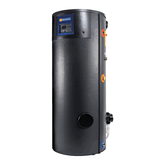
DORCHESTER DR-SG
Gas-fired condensing water heater
INSTALLATION, COMMISSIONING AND
SERVICING INSTRUCTIONS
Models
20-210, 25-210, 30-210,
35-356, 50-356, 60-356,
70-538, 80-538, 100-538, 120-538
IMPORTANT NOTE
THESE INSTRUCTIONS MUST BE READ
AND UNDERSTOOD BEFORE INSTALLING,
COMMISSIONING, OPERATING OR
SERVICING EQUIPMENT
Advertisement
Chapters
Table of Contents

Related Manuals for Hamworthy DORCHESTER DR-SG 20-210

Summary of Contents for Hamworthy DORCHESTER DR-SG 20-210
- Page 1 DORCHESTER DR-SG Gas-fired condensing water heater INSTALLATION, COMMISSIONING AND SERVICING INSTRUCTIONS Models 20-210, 25-210, 30-210, 35-356, 50-356, 60-356, 70-538, 80-538, 100-538, 120-538 IMPORTANT NOTE THESE INSTRUCTIONS MUST BE READ AND UNDERSTOOD BEFORE INSTALLING, COMMISSIONING, OPERATING OR SERVICING EQUIPMENT...
- Page 2 Site Assembly Hamworthy offer a service of site assembly for many of our products where plant room access is restricted. Using our trained staff we offer a high quality of build and assurance of a boiler built and tested by the manufacturer.
-
Page 3: Table Of Contents
DORCHESTER DR-SG - Installation, Operation and Maintenance CONTENTS Symbols used in this document ..........................4 1. WARNINGS AND RECOMMENDATIONS ................5 1.1. Transport and storage ........................... 5 1.2. Qualification of personnel for installation, adjustment, use and maintenance ..........5 1.3. Handling ................................ 6 1.4. -
Page 4: Symbols Used In This Document
DORCHESTER DR-SG - Installation, Operation and Maintenance 7.3. Cleaning the condensate evacuation pipe ....................45 7.4. Checking the combustion circuit seal ......................46 7.5. Checking the combustion quality ........................ 46 7.6. Checking the gas valve setting ........................47 7.7. Cleaning the burner and the evacuation in the by-pass and changing the seals ........48 8. -
Page 5: Warnings And Recommendations
DORCHESTER DR-SG - Installation, Operation and Maintenance The DORCHESTER DR-SG is covered by Section G3 of the Building Regulations (England and Wales) Technical Standard P3 (Scotland) and Building Regulation P5 (Northern Ireland). Compliance can be achieved via a Competent Person Self Certification Scheme or notification of installation to the Local Authority Building Control Department. -
Page 6: Handling
DORCHESTER DR-SG - Installation, Operation and Maintenance 1.3. Handling The DORCHESTER DR-SG must only be handled/moved using a pallet truck or a hand truck (see §3.4 for water heater weight). If the latter is used, the following handling recommendations MUST BE respected: •... -
Page 7: Safety Instructions
DORCHESTER DR-SG - Installation, Operation and Maintenance 1.4. Safety instructions • Always disconnect the Dorchester DR-SG from the power supply and shut off the main gas supply before carrying out any work on it. • Check that there are no gas leaks on the installation after any work on the Dorchester DR-SG (maintenance or repair). -
Page 8: Water Composition
DORCHESTER DR-SG - Installation, Operation and Maintenance 1.5. Water composition For regions with very hard water (TH>24.5 Clark degrees), it is best to use a softener to prevent scaling problems in the heating element. Excessive scaling: • Reduces device performance •... - Page 9 DORCHESTER DR-SG - Installation, Operation and Maintenance Current Gas Safety (Installation and Use) Regulations or rules in force. The appliance is suitable only for installation in GB and IE and should be installed in accordance with the rules in force. In GB, the installation must be carried out by a suitably qualified Gas Safe registered engineer or in IE by a competent person.
- Page 10 DORCHESTER DR-SG - Installation, Operation and Maintenance water for domestic use within buildings and their curtilages. Any installation must be in accordance with the relevant requirements of the Gas Safety Regulations, Building Regulations, I.E.E. Wiring Regulations and the Water Fitting Regulations (England and Wales) or Water Byelaws (Scotland).
-
Page 11: Gas Category
DORCHESTER DR-SG - Installation, Operation and Maintenance 2.2. Gas category The DR-SG water heater has been factory-set to operate with group H natural gas (type G20) with a nominal supply pressure of 20 mbar. See chapter 4.8 for how to change the gas, and use a qualified professional. INFORMATION: Any work on a sealed component will lead to loss of the guarantee. -
Page 12: Technical Specifications
DORCHESTER DR-SG - Installation, Operation and Maintenance 3. TECHNICAL SPECIFICATIONS 3.1. Dimensions DORCHESTER DR-SG XX-210 DORCHESTER DR-SG XX-356 MODELS Dorchester Dorchester Dorchester DR-SG XX-210 DR-SG XX-356 DR-SG XX-538 100 120 Hot water outlet Rp 1"1/2 Rp 1"1/2 Rp 1"1/2 Secondary return Rp 1"1/2 Rp 1"1/2 Rp 1"1/2... - Page 13 DORCHESTER DR-SG - Installation, Operation and Maintenance DR-SG DR-SG DR-SG Description XX-210 XX-356 XX-538 1802 1874 2028 Overall Height Ø 600 Ø 750 Ø 890 Diameter Height to cold water inlet Height to inspection hatch 1129 Height to secondary return 1193 1248 1373...
-
Page 14: Boiler Components
DORCHESTER DR-SG - Installation, Operation and Maintenance 3.2. Boiler components 8 Air inlet 1 Control unit 9 Air valve 2 Ionisation electrode 10 Air pressure switch 3 Ignition transformer 11 Gas valve 4 Sight glass 12 Gas mixer tap 5 Upper powered anode 13 Ignition electrode (spark train) 6 Complete display (user interface) 14 Triplex sensor (behind HMI screen) - Page 15 DORCHESTER DR-SG - Installation, Operation and Maintenance 15 Sample point 16 Lower powered anode 17 Smoke nozzle 18 Flue temperature sensor 19 NRV 20 Condensate removal siphon Dorchester DR-SG XX-356 Dorchester DR-SG XX-210 Dorchester DR-SG XX-538 13.01.2023 Page 15 / 104...
-
Page 16: Combustion At 15°C And 1013 Mbar
DORCHESTER DR-SG - Installation, Operation and Maintenance 3.3. Combustion at 15°C and 1013 mbar 3.3.1. Combustion G20 Dorchester DR-SG XX-210 20 kW 25 kW 30 kW Nominal power Pn 26.3 31.5 Rated heat input Qn Min heat input Qmin Gas flow rate at Pn (15 °C) at Qmin: 9.4 % <... - Page 17 DORCHESTER DR-SG - Installation, Operation and Maintenance Dorchester DR-SG XX-356 35 kW 50 kW 60 kW Nominal power Pn Rated heat input Qn 56.6 Min heat input Qmin 11.3 11.3 11.3 Gas flow rate at Pn (15 °C) at Qmin: 9.0 % < CO <...
- Page 18 DORCHESTER DR-SG - Installation, Operation and Maintenance Dorchester DR-SG XX-538 70 kW 80 kW 100 kW 120 kW Nominal power Pn 73.4 Rated heat input Qn 69.9 Min heat input Qmin Gas flow rate at Pn (15 °C) 12.7 at Qmin: 9.2 % < CO <...
- Page 19 DORCHESTER DR-SG - Installation, Operation and Maintenance 3.3.2. Combustion G31 Dorchester DR-SG XX-210 20 kW 25 kW 30 kW Nominal power Pn 26.3 31.5 Rated heat input Qn Min heat input Qmin Gas flow rate at Pn (15 °C) at Qmin: 10.8 % < CO <...
- Page 20 DORCHESTER DR-SG - Installation, Operation and Maintenance Dorchester DR-SG XX-356 35 kW 50 kW 60 kW Nominal power Pn Rated heat input Qn 56.6 Min heat input Qmin 11.3 11.3 11.3 Gas flow rate at Pn (15 °C) at Qmin: 10.8 % < CO <...
- Page 21 DORCHESTER DR-SG - Installation, Operation and Maintenance Dorchester DR-SG XX-538 70 kW 80 kW 100 kW 120 kW Nominal power Pn 73.4 Rated heat input Qn 69.9 Min heat input Qmin Gas flow rate at Pn (15 °C) at Qmin: 10.8 % < CO <...
-
Page 22: Operating Conditions
DORCHESTER DR-SG - Installation, Operation and Maintenance 3.4. Operating conditions Dorchester Dorchester Dorchester DR-SG DR-SG DR-SG XX-210 XX-356 XX-538 Max DHW temperature setting °C DHW safety temperature °C 7000 7000 7000 Max service pressure (bar) Water content Weight without water Acoustic power at P (Lw) * dB (A) -
Page 23: Installation
DORCHESTER DR-SG - Installation, Operation and Maintenance 4. INSTALLATION 4.1. Ventilation The appliance may only be installed in a room that complies with the requirements stated in national and local ventilation regulations. BS5440 Flueing and ventilation for gas appliances of rated input not exceeding 70 kW net (1st, 2nd and 3rd family gases) –Part 2: Specification for the installation and maintenance of ventilation provision for gas appliances. - Page 24 DORCHESTER DR-SG - Installation, Operation and Maintenance The following information is taken from Approved Document G3 of the Building Regulations and is provided to assist with the design and installation of the discharge pipework. However, the information is not exhaustive and reference should always be made to Approved Document G3 of the Building Regulations.
-
Page 25: Vented Installation
A Temperature and Pressure Relief Valve is only mandatory in unvented installations. However, Hamworthy also strongly recommends the use of a Temperature and Pressure Relief Valve in vented installations. -
Page 26: Removing The Cover Panel
DORCHESTER DR-SG - Installation, Operation and Maintenance 4.4. Removing the cover panel 1. Remove the 2 screws securing the cover 2. Remove the top cover 3. Unscrew the 2 retaining screws on each side of the display: 4. Remove the front screen. figure 3 - Screw positions for cover dismount Dorchester DR-SG XX-210 and XX-356 models have... -
Page 27: Flue Installation Connection
Dorchester DR-SG's smoke outlet or the air inlet A range of bespoke flue starter kits are available to purchase from Hamworthy, in open flue (B23) and room sealed (C type) variants. For B23 systems it is... - Page 28 The storage unit's connection part must not be made to support the IMPORTANT: exhaust duct's weight. Installation of an air filter (ref. HAMWORTHY Kit for Dorchester DR-SG XX-210: 031303, Dorchester DR-SG XX-356: 031304, Dorchester DR- SG XX-538: 031305) is strongly recommended to protect the burner IMPORTANT: tube from clogging.
- Page 29 20 kW 25 kW 30 kW 35 kW 50 kW 60 kW 70 kW 80 kW 100 kW 120 kW (B23P) (Pa) Installation of an air filter (ref. HAMWORTHY Kit for Dorchester DR-SG XX-210: 031303, Dorchester DR-SG XX-356: 031304, Dorchester DR- SG XX-538: 031305) is strongly recommended to protect the burner IMPORTANT: tube from clogging.
- Page 30 DORCHESTER DR-SG - Installation, Operation and Maintenance 4.6.3. Connection to a C13 or C33, suction pipe C13 type connection: A room sealed appliance designed for connection via ducts to a horizontal terminal, which admits fresh air to the burner and discharges the products of combustion to the outside through orifices which, in this case, are concentric.
-
Page 31: Hydraulic Connection
4.7. Hydraulic connection The following must be fitted to the cold water pipe: either: • the HAMWORTHY hydraulic kit (ref 031272), • an isolation valve, • a drain valve. • an anti-return flap • a safety valve rated at 7 bar in compliance with standard NF P 52.001 and its system for evacuating directly to the sewer. -
Page 32: Gas Change G20-G31
DORCHESTER DR-SG - Installation, Operation and Maintenance 4.8. Gas change G20-G31 This Dorchester DR-SG has been factory-set to work with group H (type G20) natural gas with a supply pressure of 20 mbar. Any operations involving changing the type of gas used must be IMPORTANT: performed by a qualified professional. - Page 33 DORCHESTER DR-SG - Installation, Operation and Maintenance 4.8.1. Change from G20 to G31 Refer to section 4.8.1.3 for instructions on how to implement the settings changes as the last step of this process 4.8.1.1. Installing the propane injector Dorchester DR-SG XX-210 models ONLY on 20 to 30kW storage tanks IMPORTANT: AA031256 - DR-SG 20-210, AA031257 - DR-SG 25-210, AA031258 - DR-...
- Page 34 DORCHESTER DR-SG - Installation, Operation and Maintenance It is essential to use the 235594 SG70-120 LPG Conversion Kit supplied as an option by HAMWORTHY. Refer to the kit instructions IMPORTANT: for installing specific components and before modifying the LMS settings, adjusting the gas valve, and adjusting the regulator.
- Page 35 DORCHESTER DR-SG - Installation, Operation and Maintenance 4.8.1.4. Adjustment of the gas valve - Before starting the burner, on the gas valve, preset the gas flow rate, using the gas flow rate adjustment screw R1, to the appropriate value given in the following table for settings - Start the burner at maximum power.
- Page 36 DORCHESTER DR-SG - Installation, Operation and Maintenance Pre-setting the gas flow adjustment Model screw R1 and the R2 / G20 regulator CO2 Pmax CO2 indicative Pmin setpoint adjusting screw Screw R1 all the way Unscrew R1 de 3,25 turns, ajust R2 20-210 (Valve set G20) Screw R1 d'1/2 turn, ajust R2...
-
Page 37: Gas Connection
DORCHESTER DR-SG - Installation, Operation and Maintenance 4.9. Gas connection Before installing the boiler, clean the interior of the gas line, which must be free of metal particles and welding debris. This will lengthen the lifespan of the product. The gas valve is fitted with an integrated filter (125µm), but this is not able to retain all the impurities contained in the gas and in the mains pipes. - Page 38 DORCHESTER DR-SG - Installation, Operation and Maintenance 4.10.1. Cable ways Cable inlets Low voltage cable entry point High voltage cable entry point Page 38 / 104 00U07337760-A...
- Page 39 DORCHESTER DR-SG - Installation, Operation and Maintenance 4.10.2. Characteristics of the electrical power supply The electrical connections will only be made when all of the other assembly operations (attachment, assembly, etc.) have been carried out on the boiler. The electrical installation must comply with CE/UKCA standards for electrical connection, and in particular, the earth connection.
- Page 40 DORCHESTER DR-SG - Installation, Operation and Maintenance 4.10.5. Electric connections to terminals B3= DHW storage tank sensor H1=External STOP/START Request BX2 = ex : DHW loop sensor B39 BX3= ex : Special probe st2 Nav=Navipass Modbus OT=Open Therm bus figure 12 - Signal terminals 230V programmable output, 1A max (alarm report) QX1=Fault report (230V)
- Page 41 DORCHESTER DR-SG - Installation, Operation and Maintenance 4.10.6. Wiring diagram figure 14 - Complete wiring diagram 13.01.2023 Page 41 / 104...
-
Page 42: Start-Up
DORCHESTER DR-SG - Installation, Operation and Maintenance 5. START-UP 5.1. Filling the boiler - Open a tap (air vent and end-of-fill check). - Check that the drain valve is closed. - Open the cold water supply valve. - Close the tap opened previously once the storage tank has been completely filled and vented. -
Page 43: Maintenance Operations
DORCHESTER DR-SG - Installation, Operation and Maintenance 7. MAINTENANCE OPERATIONS The common maintenance programme features 2 types of work : • Maintenance which is carried out every year • In-depth maintenance which is carried out every 3 years. The table below contains the actions to be carried out according to the type of maintenance operation. -
Page 44: Descaling And Cleaning Of The Storage Tank
DORCHESTER DR-SG - Installation, Operation and Maintenance 7.1. Descaling and cleaning of the storage tank Emptying the water heater • Close the cold water inlet tap. • Connect the drain valve (see § 4.4) to the drain with a suitable hose, •... -
Page 45: Cleaning The Condensate Evacuation Pipe
DORCHESTER DR-SG - Installation, Operation and Maintenance Check the spacing between the ignition electrodes (see figure opposite). It must be between 2.5 and 3.5 mm. If this is not the case, the electrode must be replaced. 2.5-3.5 mm figure 16 - Spacing Check the ignition electrode fold geometry. -
Page 46: Checking The Combustion Circuit Seal
DORCHESTER DR-SG - Installation, Operation and Maintenance 7.4. Checking the combustion circuit seal Check for leaks with a foaming product. The areas to be checked are shown in the figure opposite. The check should be carried out when the appliance is cold (water heater turned off) but with the fan at maximum speed (obtained by disconnecting the PWM signal connector - see electrical diagram). -
Page 47: Checking The Gas Valve Setting
DORCHESTER DR-SG - Installation, Operation and Maintenance 7.6. Checking the gas valve setting This Dorchester DR-SG storage tank has been adjusted in the factory to work with group H (type G20) natural gas with a supply pressure of 20 mbar. Any operations involving adjusting the gas valve must be performed by a qualified Gas Safe engineer or in... -
Page 48: Cleaning The Burner And The Evacuation In The By-Pass And Changing The Seals
DORCHESTER DR-SG - Installation, Operation and Maintenance 20 kW AT QMIN: 9.4 % < CO2 < 9.8 % DORCHESTER 25 kW DR-SG XX-210 AT QMAX: 8.6 % < CO2 < 9.0 % 30 kW 35 kW AT QMIN: 9.0 % < CO2 < 9.4 % DORCHESTER at Qmin: 0.8 % <... - Page 49 DORCHESTER DR-SG - Installation, Operation and Maintenance When extracting the burner tube, avoid rubbing its "metal covering" IMPORTANT: against the flange. Cleaning the burner tube: - Use a vacuum cleaner to clean the whole "metal covering" surface. - Check the condition of the gas manifold coating. When refitting: •...
-
Page 50: End Of Product Life
For more information on waste disposal/management, contact the Local Authority responsible for waste management or the point of sales where the product was purchased HAMWORTHY has signed up to the Eco-systèmes service which collects, recycles and cleans our used electrical equipment, according to the highest environmental requirements. -
Page 51: Hydraulic Diagrams And Configurations
DORCHESTER DR-SG - Installation, Operation and Maintenance 9. HYDRAULIC DIAGRAMS AND CONFIGURATIONS 9.1. Symbols used in the diagrams Symbol Function Symbol Function Isolation valve open Balancing valve Motorised 2-channel valve Bleed valve Fixed flow pump Outdoor sensor Temperature sensor No return valve Variable flow pump Security Group Y Strainer... -
Page 52: Dorchester Dr-Sg Only
DORCHESTER DR-SG - Installation, Operation and Maintenance Diagrams Dorchester DR-SG only DR-SG100 Dorchester DR-SG with or without de-stratification pump for anti-legionella DR-SG102 function page 1 / 3 HYDRAULIC DIAGRAM figure 23 - DR-SG100 diagram without de-stratification pump figure 24 - DR-SG102 diagram with de-stratification pump Page 52 / 104 00U07337760-A... - Page 53 DORCHESTER DR-SG - Installation, Operation and Maintenance Diagrams: DR-SG100, DR-SG102 page 2 / 3 OPTIONAL ACCESSORIES REQUIRED DR-SG100 diagram: No accessories. DR-SG102 diagram: Quantity Appliance reference Order No. DR-SG Re-circulation De-stratification pump 236166 pump OPERATING DESCRIPTION Version DR-SG 100 diagram: The Dorchester DR-SG is autonomous, the DHW setpoint is adjusted based on the desired flow temperature.
- Page 54 DORCHESTER DR-SG - Installation, Operation and Maintenance Diagrams: DR-SG100, DR-SG102 page 3 / 3 SPECIFIC START-UP PROCEDURE " Correctly install and connect the electrical connections. " Make the settings below in "specialist" mode Short press Press 3 seconds End user Commissioning Specialist Line No.
-
Page 55: Dorchester Dr-Sg + Tank(S) In Semi-Accumulated
DORCHESTER DR-SG - Installation, Operation and Maintenance Diagrams DR-SG120 Dorchester DR-SG + Tank(s) in Semi-accumulated DR-SG121 Dorchester DR-SG with volume mixing or tank load pump page 1 / 4 HYDRAULIC DIAGRAM figure 25 - DR-SG120 diagram figure 26 - DR-SG121 diagram 13.01.2023 Page 55 / 104... - Page 56 DORCHESTER DR-SG - Installation, Operation and Maintenance Diagrams: DR-SG120, DR-SG121 page 2 / 4 OPTIONAL ACCESSORIES REQUIRED Quantity Appliance reference Order No. Insertion water temp sensor QAZ 36 563605609 OPERATING DESCRIPTION The Dorchester DR-SG is coupled to 1 or 2 DHW tanks, the customer regulates the DHW setpoint he wishes to obtain at the product outlet, which will be the same setpoint for the tank(s).
- Page 57 DORCHESTER DR-SG - Installation, Operation and Maintenance Diagrams: DR-SG120, DR-SG121 page 3 / 4 CUSTOMER'S ELECTRICAL CONNECTION Wiring to modify Storage tank sensor B3 Navistem Modbus (option see § Navipass) Fault report 230Vac DHW tank pump Q3 SPECIFIC START-UP PROCEDURE "...
- Page 58 DORCHESTER DR-SG - Installation, Operation and Maintenance Diagrams: DR-SG120, DR-SG121 page 4 / 4 DHW release request Release (1620) 24/24 Setting the anti-legionella cycle (if desired) Anti-legionella function (1640) stop / periodic / fixed day Activate the anti-legionella function of the week Function anti-legionella periodical (1641) 1 to 7 days Choice of repetition.
-
Page 59: Dorchester Dr-Sg + Tank(S) In Semi-Accumulated
DORCHESTER DR-SG - Installation, Operation and Maintenance Diagram DR-SG120 Dorchester DR-SG + Tank(s) in Semi-accumulated Dorchester DR-SG with volume mixing or tank load pump page 1 / 7 HYDRAULIC DIAGRAM figure 27 - DR-SG120 bis diagram OPTIONAL ACCESSORIES REQUIRED Quantity Appliance reference Order No. - Page 60 DORCHESTER DR-SG - Installation, Operation and Maintenance Diagram: DR-SG120 bis page 2 / 7 OPERATING DESCRIPTION Dorchester DR-SG is coupled to a DHW tank, the customer regulates the DHW setpoint he wishes to obtain at the product outlet, which will be the same setpoint for the tank and the Dorchester DR-SG.
- Page 61 DORCHESTER DR-SG - Installation, Operation and Maintenance Diagrams: DR-SG120 bis page 3 / 7 CUSTOMER'S ELECTRICAL CONNECTION Wiring to modify Storage tank sen- sor B3 Navistem Modbus (option see § Navipass) Fault report 230Vac ELECTRICAL CONNECTION OF THE KIT Do not modify the switches DHW pump Q3 control signal (0-10V) IMPORTANT: The AVS 75.370 module must be installed on the plate upside down.
- Page 62 DORCHESTER DR-SG - Installation, Operation and Maintenance Diagram: DR-SG120 bis page 4 / 7 SPECIFIC START-UP PROCEDURE " Correctly install and connect the electrical connections. " Make the settings below in "specialist" mode Short press Press 3 seconds End user Commissioning Specialist Line No.
- Page 63 DORCHESTER DR-SG - Installation, Operation and Maintenance Diagram: DR-SG120 bis page 5 / 7 Setting the anti-legionella cycle (if desired) Anti-legionella function (1640) stop / periodic / fixed day Activate the anti-legionella function of the week Function anti-legionella periodical (1641) 1 to 7 days Choice of repetition.
- Page 64 DORCHESTER DR-SG - Installation, Operation and Maintenance Diagram: DR-SG120 bis page 6 / 7 • Timer program menu 4/DHW Preselection (560) e.g.: Monday-Sunday Choose the programming range 1st phase ON (561) e.g.: 06:00 h Set the start of the comfort setpoint range 1st phase Off (562) e.g.: 22:00 h Set the end of the comfort setpoint range...
-
Page 65: Dorchester Dr-Sg + Tank(S) Semi-Instant
DORCHESTER DR-SG - Installation, Operation and Maintenance Diagrams Dorchester DR-SG + Tank(s) Semi-instant DR-SG130 Dorchester DR-SG and tank(s) with volume mixing DR-SG131 or tank load pump page 1 / 5 HYDRAULIC DIAGRAM Permanent power supply figure 28 - DR-SG130 diagram Permanent power supply figure 29 - DR-SG131 diagram... - Page 66 DORCHESTER DR-SG - Installation, Operation and Maintenance Diagrams: DR-SG130, DR-SG131 page 2 / 3 OPTIONAL ACCESSORIES REQUIRED No accessories needed. OPERATING DESCRIPTION The Dorchester DR-SG is coupled to 1 or 2 DHW tanks, the customer regulates the DHW setpoint he wishes to obtain at the product outlet, which will be the same setpoint for the tank(s). A pump is added between the tank and the Dorchester DR-SG that allows the entire volume to be permanently stirred.
- Page 67 DORCHESTER DR-SG - Installation, Operation and Maintenance Diagrams: DR-SG130, DR-SG131 page 3 / 5 CUSTOMER'S ELECTRICAL CONNECTION SPECIFIC START-UP PROCEDURE " Correctly install and connect the electrical connections. " Make the settings below in "specialist" mode Short press Press 3 seconds End user Commissioning Specialist...
- Page 68 DORCHESTER DR-SG - Installation, Operation and Maintenance Diagrams: DR-SG130, DR-SG131 page 4 / 5 Differential (5024) 5 °C DHW restart hysteresis • Switch the DHW mode to permanent comfort (as per parameter 1620) • Switch the DHW regime to permanent reduced If you want to lower the DHW setpoint (reduced setpoint) for a specific time range, use the following settings...
-
Page 69: Dorchester Dr-Sg Cascade Without Tank(S)
DORCHESTER DR-SG - Installation, Operation and Maintenance Diagrams Dorchester DR-SG Cascade without tank(s) DR-SG140 Hydraulic cascade of 2 Dorchester DR-SGs page 1 / 4 HYDRAULIC DIAGRAM figure 30 - DR-SG140 diagram OPTIONAL ACCESSORIES REQUIRED No accessories needed 13.01.2023 Page 69 / 104... - Page 70 DORCHESTER DR-SG - Installation, Operation and Maintenance Diagram: DR-SG140 page 2 / 4 OPERATING DESCRIPTION Despite the Dorchester DR-SGs being mounted in a hydraulic cascade, there is no communication between the 2 products. /!\ It is imperative that both the Dorchester DR-SGs have the same settings and the same operating mode.
- Page 71 DORCHESTER DR-SG - Installation, Operation and Maintenance Diagram: DR-SG140 page 3 / 4 SPECIFIC START-UP PROCEDURE " Correctly install and connect the electrical connections. " Make the settings below in "specialist" mode Short press Press 3 seconds End user Commissioning Specialist Line No.
- Page 72 DORCHESTER DR-SG - Installation, Operation and Maintenance Diagram: DR-SG140 page 4 / 4 • Switch the DHW mode to permanent comfort (as per parameter 1620) • Switch the DHW regime to permanent reduced If you want to lower the DHW setpoint (reduced setpoint) for a specific time range, use the following settings Line No.
-
Page 73: Dorchester Dr-Sg Cascade With Tank(S)
DORCHESTER DR-SG - Installation, Operation and Maintenance Diagrams Dorchester DR-SG Cascade with tank(s) DR-SG160 Dorchester DR-SG cascade with tank, with or without manual bypass of the DR-SG161 safety mixing tap for the anti-legionella cycle page 1 / 5 HYDRAULIC DIAGRAM Permanent power supply figure 31 - DR-SG160 diagram... - Page 74 DORCHESTER DR-SG - Installation, Operation and Maintenance Diagrams: DR-SG160, DR-SG161 page 2 / 4 REGULATION ACCESSORIES REQUIRED No accessories needed. OPERATING DESCRIPTION Despite the Dorchester DR-SG being mounted in a hydraulic cascade, there is no communication between the 2 products. /!\ It is imperative that both the Dorchester DR-SGs have the same settings and the same operating mode.
- Page 75 DORCHESTER DR-SG - Installation, Operation and Maintenance Diagrams: DR-SG160, DR-SG161 page 3 / 4 SPECIFIC START-UP PROCEDURE " Electrically assemble and connect the 2 Dorchester DR-SGs " Connect the DHW tank loading pump to the boiler room's electrical cabinet and activate it as soon as the product is switched on.
- Page 76 DORCHESTER DR-SG - Installation, Operation and Maintenance Diagrams: DR-SG160, DR-SG161 page 4 / 4 • Switch the DHW mode to permanent comfort (as per parameter 1620) • Switch the DHW regime to permanent reduced If you want to lower the DHW setpoint (reduced setpoint) for a specific time range, use the following settings Line No.
- Page 77 DORCHESTER DR-SG - Installation, Operation and Maintenance page 1/ 4 External commands mode For a product blocking request made by external information with a VF contact Line No. Value • Configuration menu Configure input H1 to make an on/off command by dry contact H1 input function (5950) Blocked generator, waiting If you want the blocking command to be...
- Page 78 DORCHESTER DR-SG - Installation, Operation and Maintenance page 2/ 4 External commands mode To modify the DHW temperature setpoints via the Modbus bus Line No. Value There is no need to change settings on the product when using Modbus communication •...
- Page 79 DORCHESTER DR-SG - Installation, Operation and Maintenance page 3/ 4 External commands mode List of DHW statuses Register 196 Text Line No. 8003 Safety thermostat Manual mode Under load Antifreeze protection Antifreeze protection Stop Adiabatic cooling Electrical resistance load Overheating other circuit Under load Under load Under load...
-
Page 80: Electrical Validation
DORCHESTER DR-SG - Installation, Operation and Maintenance 10. ELECTRICAL VALIDATION Dorchester DR-SG Line No. Value • Menu Input / output tests Check the sensor values External T° B9 (7750) ---°C DHW sensor B3 Enable outputs Relay test(7700) Output QX1 Alarm output Programmable output QX2 Relay test(7700) Output QX2 Relay test(7700) No test... - Page 81 DORCHESTER DR-SG - Installation, Operation and Maintenance OPERATING DESCRIPTION This kit allows you to monitor the temperature of a secondary hot water loop. You can read the value of this temperature at parameter 8835 and set an alarm that will be stored in the fault history.
- Page 82 DORCHESTER DR-SG - Installation, Operation and Maintenance SPECIFIC START-UP PROCEDURE Line No. Value • Configuration menu Configure the secondary loop monitoring temperature sensor Sensor input Bx3 (5932) DHW flow temperature sensor B39 • Heating gas menu DHW Choose setpoint for DHW secondary loop Flow temperature setpoint (1663) __°C Choose trigger timeout of the alarm Secondary loop alarm timeout (1668) __ hour...
-
Page 83: Spare Parts List
DORCHESTER DR-SG - Installation, Operation and Maintenance 12. SPARE PARTS LIST Dorchester Dorchester Dorchester DR-SG XX-210 DR-SG XX-356 DR-SG XX-538 Item Designation 20 to 30 kW 35 to 60 kW 70 to 120 kW Top cover AA555346 AA555361 AA555362 Cable passage plate AA555369 Cladding screen AA555366... - Page 84 DORCHESTER DR-SG - Installation, Operation and Maintenance Model XX-210 Model XX-356 Model XX-538 Page 84 / 104 00U07337760-A...
- Page 85 DORCHESTER DR-SG - Installation, Operation and Maintenance Dorchester Dorchester Dorchester DR-SG XX-210 DR-SG XX-356 DR-SG XX-538 Item Designation 20 to 30 kW 35 to 60 kW 70 to 120 kW Tank insulating wedge AA555432 Upper tank insulation AA555424 AA555427 AA555431 Outlet tapping insulation AA555434 AA555435...
- Page 86 DORCHESTER DR-SG - Installation, Operation and Maintenance Models XX-210 and XX-356 Models XX-210 and XX-356 Model XX-538 Model XX-538 Page 86 / 104 00U07337760-A...
- Page 87 DORCHESTER DR-SG - Installation, Operation and Maintenance Dorchester Dorchester Dorchester DR-SG XX-210 DR-SG XX-356 DR-SG XX-538 Item Designation 20 to 30 kW 35 to 60 kW 70 to 120 kW Cable passage plate AA555369 Panel rear bracket AA555476 Panel lock AA555485 Panel left side jacket AA555474...
- Page 88 DORCHESTER DR-SG - Installation, Operation and Maintenance Models XX-210 Models XX-356 and XX-538- Dorchester Dorchester Dorchester DR-SG XX-210 DR-SG XX-356 DR-SG XX-538 Item Designation 20 to 30 kW 35 to 60 kW 70 to 120 kW Control panel sheet AA555537 AA555538 70kW: AA555493...
- Page 89 DORCHESTER DR-SG - Installation, Operation and Maintenance Model XX-568 Models XX-210 and XX-356 Dorchester Dorchester Dorchester DR-SG XX-210 DR-SG XX-356 DR-SG XX-538 Item Designation 20 to 30 kW 35 to 60 kW 70 to 120 kW Complete Navistem display AA555438 Mounting + Navistem led board AA555439 AVS37 ribbon cable...
- Page 90 DORCHESTER DR-SG - Installation, Operation and Maintenance Models XX-210 Dorchester Dorchester Dorchester DR-SG XX-210 DR-SG XX-356 DR-SG XX-538 Item Designation 20 to 30 kW 35 to 60 kW 70 to 120 kW Ignition electrode AA555554 AA555556 Ionisation electrode AA555553 Flame viewer AA555571 AA555572 Burner flange...
- Page 91 DORCHESTER DR-SG - Installation, Operation and Maintenance Models XX-356 Models XX-538 13.01.2023 Page 91 / 104...
-
Page 92: Customer Regulation Parameters Table
DORCHESTER DR-SG - Installation, Operation and Maintenance 13. CUSTOMER REGULATION PARAMETERS TABLE Storage tank: ..........site: ..........serial no: ....................Please transfer all parameter modifications into this document! Note: The "access" column indicates the level of accessibility to information for programming (U for end user, M for commissioning and S for specialist). - Page 93 DORCHESTER DR-SG - Installation, Operation and Maintenance Line Programming Default value Customer setting Access DHW gas heating 1610 Comfort setpoint 65 °C 1612 Reduced setpoint 65 °C 1614 Max comfort setpoint 80 °C 1620 Release 24/24 1640 Anti-legionella function stop 1641 Periodic anti-legionella function 1642 Anti-legionella function day week Monday...
- Page 94 DORCHESTER DR-SG - Installation, Operation and Maintenance Line Programming Default value Customer setting Access 2442 Max. charge full fan speed 20-210: 6030 rpm 25-210: 7390 rpm 30-210: 8500 rpm 35-356: 6250 rpm 50-356: 8890 rpm 60-356: 9800 rpm 70-538: 3810 rpm 80-538: 4330 rpm 100-538:...
- Page 95 DORCHESTER DR-SG - Installation, Operation and Maintenance Line Programming Default value Customer setting Access 5581 dT°regul off dT 2 10 °C 5582 Regul min act time dT 2 0 °C 5583 Sensor 1 regulator dT 2 none 5584 Sensor 2 regulator dT 2 none 5585 Min regul on time dT2 5587 Pump/valve kick-start K21...
- Page 96 DORCHESTER DR-SG - Installation, Operation and Maintenance Line Programming Default value Customer setting Access 6067 Mod. 3 H2 voltage 2 value 3 (U2) 6068 Module 3 H2 funct. value 2 (F2) 6100 Ext. T° sensor correction 0 °C 6120 Installation antifreeze stop 6127 Valve/pump kick-start duration 30 s...
- Page 97 DORCHESTER DR-SG - Installation, Operation and Maintenance Line Programming Default value Customer setting Access 6810 History 2 00:00 6815 Software diagnostic code 2 6820 History 3 00:00 6825 Software diagnostic code 3 6830 History 4 00:00 6835 Software diagnostic code 4 6840 History 5 00:00 6845 Software diagnostic code 5...
- Page 98 DORCHESTER DR-SG - Installation, Operation and Maintenance Line Programming Default value Customer setting Access 7130 Chimney function stop 7131 Burner power max. burner load 7140 Manual mode stop 7143 Regulator stop function 7145 Regulator stop setpoint 100% 7146 Drain function 7147 Drain type 7170 After Sales Department telephone 7250 Pos memory Pstick...
- Page 99 DORCHESTER DR-SG - Installation, Operation and Maintenance Line Programming Default value Customer setting Access 8308 Boiler pump speed 8310 Boiler temperature 8311 Boiler setpoint 8312 Boiler switching point 8313 Regulation sensor 8314 Boiler return temperature 8316 Fume temperature 8318 Max burnt gas temperature 8323 Fan speed 8324 Burner fan setpoint 8325 Current fan command...
- Page 100 DORCHESTER DR-SG - Installation, Operation and Maintenance Line Programming Default value Customer setting Access 9054 Relay output QX22 module 2 9055 Relay output QX23 module 2 9056 Relay output QX21 module 3 9057 Relay output QX22 module 3 9058 Relay output QX23 module 3 Safety unit 9504 Preventilat.
- Page 101 DORCHESTER DR-SG - Installation, Operation and Maintenance Line Programming Default value Customer setting Access 9626 Power slope/fan speed 20-210: 301.6 133.3 25-210: 296.6 174.5 30-210: 283.8 143.0 35-356: 178.6 161.0 50-356: 178.0 147.8 60-356: 163.4 146.7 70-538: 54.5 49.6 80-538: 54.2 43.4 100-538:...
- Page 102 DORCHESTER DR-SG - Installation, Operation and Maintenance 14. APPENDIX A Product data ≤ 400 kW Product reference Trade mark HAMWORTHY Model 20 KW 25 KW 30 KW 35 KW 50 KW 60 kW Code 031245 031246 031247 031248 031249 031250...
- Page 103 DORCHESTER DR-SG - Installation, Operation and Maintenance 13.01.2023 Page 103 / 104...
- Page 104 Wessex House, New Fields Business Park, Stinsford Road, Poole, Dorset, BH17 0NF Telephone: 01202 662500 Fax: 01202 662522 Email: aftersales@hamworthy-heating.com Website: www.hamworthy-heating.com Hamworthy reserves the right to make changes and improvements which may necessitate alteration to the specification without prior notice.
Need help?
Do you have a question about the DORCHESTER DR-SG 20-210 and is the answer not in the manual?
Questions and answers